
Instruction manual
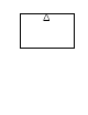
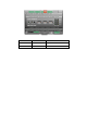
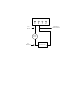
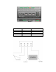

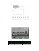

You can connect the dry contact relay outputs on the SmartServer to a voltage source and a load.
When an ON value is asserted, the cir c uit will be closed and the voltage source will drive the load.
The following figure demonstr ates this configurat ion.
5 6 7 8
Resistive Load
Switched DC +
Switched AC Line
DC -
AC Neutral
Voltage
Source
DC +
AC Line
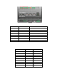
Inductive loa ds such as motors, r ela ys, or co ntactors present a special case for the SmartServer relay
contacts. A hig h voltage k nown as a b ack or counter EMF is created across an inductive load when
interrupt ing the c urrent flow through it due to the change in electromagnetic field. This vol t age ca n often
be in the range of several kV. In the case of inductive DC loads such as relays, use a protection diode
across the load to eliminate the back EMF. In the case of inductive AC loads, use series resistor, capacitor
(RC) snubbers across either the load or contacts to limit the rate of change of voltage and peak voltage
apparent across the contacts. You can also use metal oxide varistors in parallel with RC snubbers to further
limit the peak vo lta ge. The pea k voltage across the SmartServer rela y contacts must be kept within t he
440VAC switching limit.
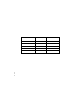
In addition, switching AC inductive loads can also create further issues due to the radiated differential a nd
common mode noise created, even when snubbers are used. This noise can potentially cause damage and
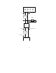
interference to adjacent electronics, such as modems. To a void this effect, use a so lid state re la y (SSR) to
switch the load where the contro l voltage for the SSR is supplied through the S martServer rela y. A n SSR
still requires a load or contact snubber and overvoltage protection; Crydom (http://www.crydom.com) can
supp ly SSRs with these features integrated into a single package. SSR contro l c urrents tend to be quite
small and if necessary to keep within the minimum switching current of the relay contacts, a parallel
resistive load must be used i f the control load for the SmartServer output is less than 5V at 100mA .
The following figure demonstr ates this configurat ion.
14 Assembling the SmartServer Hardware