
Instruction manual


DC Voltage
Source
Inductive Load
DC +
DC -
Inductive Load
AC Line
AC Neutral
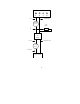
SSR
- Control +
Output
Load
Resistor
5 6 7 8
AC Voltage
Source
Switched AC Line
Switched DC +
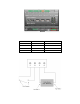
Pulse Meter Inputs
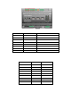
The SmartServer includes two impulse meter inputs that comply with the DIN 43 864 impulse standard
(open terminal voltage <12VDC, maxi mum c urrent ≤27mA). The pulse meter input connections are
implemented on screw terminals 9–12: Meter 2 is connected to terminals 9-10; Meter 1 is connected to
terminals 11-12. These connections are polarity-sensitive: terminals 9 and 11 are marked negative (-),
and terminals 10 and 12 are marked positive (+). You cannot reverse the polarity of the pulse meter
inputs because it will cause improper operation of the measure ment circuits.
Each of the pulse meter inputs is controlled b y a Pulse Counter a pplication on the S martSer ver. A
pulse input meter registers a p ulse when the circuit between its p ositive and negative conn e c tions is
closed (the voltage is 0) for 30ms or longer. The circuit must be open for a minimum of 30ms between
pulses. See Chapter 9 of the SmartServer 2.2 U ser’s Gui de for c onfiguring the SmartServer t o use the
pulse meter inputs to which it is connected.
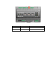
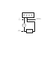
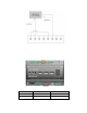
The following figure illustrates the locatio n of the pulse meter input screw terminals on t he
SmartServer.
SmartServer 2.2 Hardware Guide 15