
Instruction manual

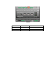
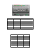
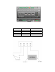


The following table lists the enclosure mar kings for the pulse meter input screw terminals o n t he
SmartServer and their connection type.
Screw Terminal
Enclosure Marking
Pulse Meter Connection
9
Meter2-
- Signal from Meter 2
10
Meter 2+
+Signal from Meter 2
11
Meter 1-
- Signal from Meter 1
12
Meter 1+
+ Signal from Meter 1
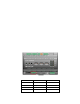
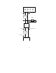
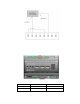
You can connect the pulse me ter inputs on the SmartServer to either a dry contact relay, or to an active
device output that generates pulses by closing the circuit between the two terminals. The following
figure demonstrates both of these configurations.
16 Assembling the SmartServer Hardware