
Instruction manual


Digital Inputs
The SmartServer has two optically isolated, polarity-sensitive d igital inputs that you can use to monitor
switch and sens or devices. The digital inp ut connections are implemented on screw terminals 13–16:
Input 2 is connected to terminals 13-14; I nput 1 is connected to terminals 15–16. These connections
are pola rity-sensitive: terminals 14 and 16 are marked positive (+), and terminals 13 and 15 are marked
negative (-). You cannot reverse the polarity of the digital inputs becau se it will cause imprope r
operation of the monitoring circuits.
Each of the digital inputs is controlled by a Digital Input applic a tion on the SmartServer. See Chapter
9 of the SmartServer 2.2 User’s Guide for configuring the SmartServer to use the digital i np uts.
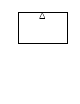
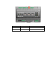
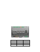
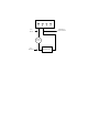
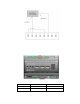
The following figure illustrates the locatio n of the digital input screw ter mina ls on the Sma r tSe rver.
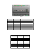
The following table lists the enclosure markings for the digi ta l inp ut screw terminals on the
SmartServer and their co nnect ion type.
Screw Terminal
Enclosure Marking
Digita l Input C onnectio n
13
Input 2-
- Signal from input 2
14
Input 2+
+ Signal from input 2
15
Input 1-
- Signal from input 1
16
Input 1+
+ Signal from input 1
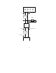
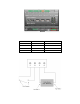
You can connect the digital inputs on the Sma rtServer to a set of dry contacts, or to an active device
output. The +12V < 20mA scre w termin als (19–20), which are described in the next section, can be
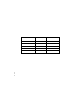
used as a voltage source for th e digital inputs. The following figure demonstrates this configuration.
In thi s figure the connection between screw terminals 16 and 20 does not include screw terminal 19, a s
it is connected to the active device.
SmartServer 2.2 Hardware Guide 17