
Instruction manual
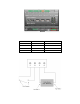


Connecting the Ether net Port
After you have connected all the required screw terminals on the SmartServer for yo ur s ys te m, yo u can
connect the RJ -45 10/100 BaseT Ethernet on the SmartServer to an Ethernet swit ch or hu b that can
communicate with your computer. This will connect the SmartServer to an IP netwo rk, and e nable you
to configure the SmartServer with its b uilt-in Web pages.
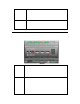
You c an connect the Ethernet port on the SmartServer to an IP network usi ng a Categor y 5, 5 e, or
Category 6 Ethernet cable with computer RJ-45 male connectors on both ends. You connect one end
of the Ethernet cable to the Etherne t port on the Sma rtServer, and the n con nect the other end t o an
Ethernet switch or hub. The SmartServer will then a utomatically adjust to the speed of the data port,
illuminate t he L AN L ink LED indic ator on the fro nt panel of the SmartServer device indicating that a
connection has been made, and illuminate the LAN 100 LED indicator if a 100BaseT network
connection has been established.
The SmartServer automatically detects whether it is connected to an Ethernet switch or hub or direct ly
to a computer; therefore, you can use a straight-through or crossover Ethernet cable.
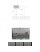
Connecting the Console Port
You can connect the console port on the SmartServer so t hat you configure t he TCP /IP, security, time,
and other properties of th e SmartServer using its console a pplication. U sing the conso le a pplication is
an alt ernative t o co nfiguring the Smart S erver with its built-in Web pages. For more information on
using the SmartServer console application, see Appendix B of the SmartServer 2.2 U ser’s Gui de.
To connect the console port on the SmartServer, connect one end of a RS-232 null modem cable that
has female connectors on both ends to the console port on the SmartServer, and then connect the other
end to one of the COM ports on yo ur computer. You can the n use a terminal emulatio n program such
as PuTTY on t he computer to access the SmartServer console application. The default
communication properties of the SmartServer are 9600- 8-None-1-None.
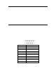
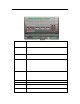
The following figure displa ys the alignment of the connector pins on the SmartServer console port, and
the subsequent table describes each of the connector pins.
DB-9 (DTE) Pin
Description
1
NC (No connect)
2
RxD (Receive Data)
3
TxD (Transmit Data)
4
NC (No connect)
5
GND (Ground)
6
NC (No connect)
7
NC (No connect)
8
NC (No connect)
9
NC (No connect)
DB-9 Shel l
Ear th Ground
Note: Pin 1 of the RS-232 console port can be attached to the carrier detect line of an external GSM
modem.
SmartServer 2.2 Hardware Guide 19