MultiModem® ZBA MT5634ZBA-Series MT5634ZBA MT5634ZBA MT5634ZBA-Global MT5634ZBA-V92 MT5634ZBA-V-V92 User Guide
Copyright and Technical Support MultiModem ZBA MT5634ZBA-Series User Guide MT5634ZBA, MT5634ZBA-Global, MT5634ZBA–V.92, MT5634ZBA-V–V.92 PN S000286H, Version H Copyright This publication may not be reproduced, in whole or in part, without prior expressed written permission from Multi-Tech Systems, Inc. All rights reserved. Copyright © 2003-11, by Multi-Tech Systems, Inc. Multi-Tech Systems, Inc.
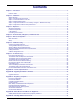
Contents Chapter 1 – Introduction................................................................................................................................................ 5 Features Table ......................................................................................................................................................... 5 Chapter 2 – Installation.........................................................................................................................................
Table of Contents Appendix F – Connecting to a Cisco Router ............................................................................................................. 37 13BAppendix G – ROHS HT/TS Substance Concentration ............................................................................................. 40 Index .............................................................................................................................................................................
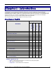
Chapter 1 – Introduction Congratulations on your purchase of the MultiModem ZBA modem. You have acquired one of the finest intelligent voice/data/fax modems available today from one of the world’s oldest modem manufacturers: Multi-Tech Systems, Inc. The MT5634ZBA-Series is available in global and non-global builds with and without the voice feature. The MT5634ZBA global product is approved in 40+ countries. The MT5634ZBA with the voice feature supports voice mail and a full-duplex speakerphone.
Chapter 1 – Introduction Features Specific to V.92 • Speed – V.92/56K download speeds and 48K upload speeds when connecting with V.92 server. • Fax – Class 1, 1.0, 2, and 2.1 faxing at speeds to V.34/33.6K bps (Super G3). • Compression – V.44 compression improves data throughput rates. • Quick Connect – Quick connect can cut the time required for a dial-up modem to “handshake” to an ISP or other connection in half. Please note that some V.
Chapter 2 – Installation This chapter describes how to set up your Multi-Tech MT5634ZBA modem. Safety Warnings ● ● ● ● ● ● ● ● ● Use this product only with UL- and CUL-listed computers (U.S.A. and Canada) To reduce the risk of fire, use only 26 AWG (.41mm) or larger telephone wiring. Never install telephone wiring during a lightning storm. Never install a telephone jack in a wet location unless the jack is specifically designed for wet locations.
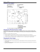
Chapter 2 – Installation Location of the Jumpers Note: J8 is the Jumper for the Modem with Voice Option Changing the Dial-Up/Leased-Line Jumper As shipped from the factory, your modem is configured for normal dial-up operation. That is, the modem must dial a phone number to connect to another modem. To use the modem on a leased line, you must change jumper J10 to select leased line operation, and J11 to select whether it will be the originating or the answering modem.
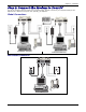
Chapter 2 – Installation Step 2: Connect the Modem to Your PC Turn off your computer. Place the modem in a convenient location, and then connect it to your computer’s serial port, the telephone line or leased line, AC power, and, optionally, your telephone. Global Connections Connections - No Voice Connections With Voice Non-Global Connection PWR RS232 PHONE Multi-Tech Systems, Inc.
Chapter 2 – Installation Connect the Modem to Your PC Plug one end of the serial cable into the RS232 connector on the modem and the other end into a serial port connector on your computer, such as COM1 or COM2. Connect the Modem to the Telephone Line Plug one end of the modular telephone cable into the modem’s LINE jack and the other end into a standard phone wall jack. Important: The LINE jack is not interchangeable with the PHONE jack.
Chapter 2 – Installation Step 3: Install the Modem Driver If you use Windows 2000 or above, you must install the modem driver. The modem driver tells Windows how to control the modem. If you use a Linux operating system, please see Appendix D. If you use another operating system, please refer to its documentation for modem installation information. Installing the Modem Driver 1. With your computer turned off, ensure that your modem is connected properly, and then turn on your computer.
Chapter 2 – Installation Step 4: Configure the Modem for Your Country or Region – Global Product Only Different countries have different requirements for how modems must function. Therefore, before you use your modem, you must configure it to match the defaults of the country/region in which you are using it. You must also do this if you move the modem to another country/region after it has been configured for the first country/region. You can use one of two configuration methods: 1.
Chapter 2 – Installation Step 5: Configure the modem for best performance With Microsoft Operating System, you can configure your modem using HyperTerminal. Ensure that there are not other applications running that could take control of the com port to which the modem is connected. Disable fax service and routing and remote access if running. To configure your modem: 1. Ensure that the modem serial cable supplied with your modem is connected. 2.
Chapter 3 – Operation About the Front Panel The LED indicators on the front panel indicate status, configuration, and activity: TD – Transmit Data. Flashes when the modem is transmitting data to another modem. RD – Receive Data. Flashes when the modem is receiving data. CD – Carrier Detect. Lights when the modem detects a valid carrier signal from another modem. It is on when the modem is communicating with the other modem, and off when the link is broken. 56 – 56K Mode (56,000–28,000 bps).
Chapter 3 – Operation Leased-Line Operation The MultiModem ZBA modem can be used on a two-wire leased line. A leased line is a private, permanent telephone connection between two points. Unlike normal dialup connections, a leased line is always active. The modems automatically connect when they are attached to the line and are turned on.
Chapter 4 – AT Commands, SRegisters, and Result Codes The AT Commands, S-Registers, and Result Codes for the MT5634ZBA-Series Modems are published in a separate Reference Guide. All reference guides are included on the Multi-Tech website. 16 Multi-Tech Systems, Inc.
Chapter 5 – Remote Configuration Remote configuration is a network management tool that allows you to configure MT5634ZBA modems remotely from one location. With password-protected remote configuration, you can issue AT commands to a remote modem for maintenance or troubleshooting as if you were on site. Basic Procedure Use the following steps when the connection is established by the local or the remote modem.
Chapter 6 – Callback Security This chapter describes how to use callback security with your modem. Callback security protects your network from unauthorized access and helps control long-distance costs. When callback security is enabled, all callers enter a password. If a valid password is received, the modem hangs up and returns the call by dialing a phone number that is stored with the password. The person being called back then re-enters the password to establish a connection.
Chapter 6 – Callback Security Setting Callback Security Message Parity The modem’s parity must match the parity of the computer to which the modem is connected. 1. Open a data communications program such as HyperTerminal. 2. In the terminal window, type AT#Sxxxxxxxx, where xxxxxxxx is your password. Press ENTER. The modem responds with OK if the setup password is correct and ERROR if it is wrong. 3. The modem’s parity default value is No parity (AT#CBP0).
Chapter 6 – Callback Security Calling Procedures Use the following procedures to call a modem that has callback security enabled. Note that Autoanswer must be enabled on the calling modem (S0=1). Password-Only Callback Use this procedure when calling from a fixed location. 1. Using a data communications program such as HyperTerminal, dial the number of the callback modem. 2. When the connection is established, the callback modem responds with the following message: Password> 3.
Chapter 6 – Callback Security Extension-Entry Callback Use this procedure when calling from an extension at the callback number. The password that you use must be set up for an optional extension-entry callback. 1. Using a data communications program such as HyperTerminal, dial the number of the callback modem. 2. When the connection is established, the callback modem responds with the following message: Password> 3.
Chapter 6 – Callback Security Callback Assignments Form Location Password Telephone Number 0 1 2 3 4 5 6 7 8 9 10 11 12 13 14 15 16 17 18 19 20 21 22 23 34 25 26 27 28 29 22 Multi-Tech Systems, Inc.
Chapter 7 – Troubleshooting Your modem was thoroughly tested at the factory before it was shipped. If you can’t make a successful connection, or if you experience data loss or garbled characters during your connection, it is possible that the modem is defective. However, it is more likely that the source of your problem lies elsewhere. The following symptoms are typical of problems you might encounter: ● None of the LEDs light when the modem is on. ● The modem does not respond to commands.
Chapter 7 – Troubleshooting ● Your communication software settings may not match the physical port to which the modem is connected. The serial cable might be plugged into the wrong connector—check your computer documentation to make sure. Or you might have selected a COM port in your software other than the one the modem is physically connected to—compare the settings in your software to the physical connection.
Chapter 7 – Troubleshooting o If you must dial 9 to get an outside line, the easiest way to dial it automatically is to include it in the modem’s dial prefix; e.g., ATDT9. Note the comma, which inserts a pause before the number is dialed. By inserting 9, into the dial prefix, you do not have to include it in each directory entry.
Chapter 7 – Troubleshooting ● Are you trying to send a file to another client modem? If so, then your maximum possible connect speed is 33,600 bps. You can upload at speeds up to 48,000 bps only when connected to an ISP that supports the V.92 protocol. ● Try entering the I11 command or the &V command in command mode to display information about the last connection, making a screen print of the connection statistics, and checking for parameters that might be unacceptable.
Appendix A – Technical Specifications The MT5634ZBA-Series modem meets the following specifications: Trade Name MultiModem ZBA Model Number MT5634ZBA Build Number MT5634ZBA, MT5634ZBA-Global, MT5634ZBA–V92, MT5634ZBA-V–V92 Server-to-Client Data Rates 56K speeds when accessing a V.90 or V.92 server (actual speed depends on server capabilities and line conditions) Client-to-Server Data Rates Up to 48Kbps when accessing a V.
Appendix A – Technical Specifications Receiver Sensitivity -43 dBm under worst-case conditions AGC Dynamic Range 43 dB Interface TIA/EIA RS-232C/ITU-T V.24/V.28 Connectors DB25F RS-232C connector; 2 RJ-11 telephone jacks; power jack Cables Country-specific telephone; power cables; serial cable Note: Any cables connected to the computer should be shielded to reduce interference. Diagnostics Power-on self test, local analog loop, local digital loop, remote digital loop.
Appendix B – Upgrading the Modem’s Firmware Your modem is controlled by semi-permanent software, called firmware, which is stored in flash memory. Firmware is nonvolatile; that is, it remains stored in memory when the modem is turned off. However, it can be changed by either the manufacturer or the user as bugs are fixed or new features are added. Since the firmware in your modem is stored in flash memory, you can use the following procedures to upgrade it yourself.
Appendix B – Upgrading the Modem’s Firmware Step 3: Download the Upgrade File 1. If you are not already at the MultiModem ZBA Firmware page of the Multi-Tech Web site, follow the procedure in “Step 2: Identify the Current Firmware.” 2. Download the upgrade file for your modem by clicking its name, and save the file in a temporary folder on your hard disk. 3. In the same section of the Web page, click the Flash Wizard utility for your operating system to download it, and save it in the same folder.
Appendix C – Regulatory Compliance FCC Part 15 Regulation This equipment has been tested and found to comply with the limits for a Class B digital device, pursuant to Part 15 of the FCC rules. These limits are designed to provide reasonable protection against harmful interference in a residential installation. This equipment generates, uses, and can radiate radio frequency energy, and if not installed and used in accordance with the instructions, may cause harmful interference to radio communications.
Appendix C – Regulatory Compliance Canadian Limitations Notice Notice: The ringer equivalence number (REN) assigned to each terminal device provides an indication of the maximum number of terminals allowed to be connected to a telephone interface. The termination on an interface may consist of any combination of devices subject only to the requirement that the sum of the ringer equivalence numbers of all the devices does not exceed 5. Notice: The Industry Canada label identifies certified equipment.
Appendix C – Regulatory Compliance New Zealand Telecom Warning Notice 1. The grant of a Telepermit for any item of terminal equipment indicates only that Telecom has accepted that the item complies with minimum conditions for connection to its network. It indicates no endorsement of the product by Telecom, nor does it provide any sort of warranty.
Appendix D – Waste Electrical and Electronic Equipment WEEE (Waste Electrical and Electronic Equipment) Statement July, 2005 The WEEE directive places an obligation on EU-based manufacturers, distributors, and retailers to take-back electronics products at the end of their useful life. A sister Directive, ROHS (Restriction of Hazardous Substances) complements the WEEE Directive by banning the presence of specific hazardous substances in the products at the design phase.
Appendix E – Installing a Modem under Linux This appendix explains how to install a modem on a computer operating under the Red Hat Linux 6.2 operating system. Other versions of Red Hat and other Linux operating systems should be similar. In Linux you do not need drivers for most standard external modems and most internal ISA bus modems. Programs in Linux commonly call upon the port, rather than the modem.
Appendix E – Installing a Modem under Linux Calling the ISP 1. On the Task Bar at the bottom of the screen, select the Gnome Footprint. 2. Select Internet from the menu. 3. Select RH PPP Dialer. 4. Select the connection name you entered in step 5 of the previous section. 5. Click OK. Answering Calls To use the system for answering calls, Linux requires other programs to be installed, such as Mgetty, Mgetty+Sendfax, and others, depending on your requirements.
Appendix F – Connecting to a Cisco Router Connecting to a Cisco Router Console Port The console port on the Cisco IOS® router is an asynchronous serial port configured as data communications equipment (DCE). For Cisco 1000, 1600, 2500, 2600, and 3600 series routers, the console port uses an RJ-45 connector. Warning: Do not connect the modem to the Cisco router’s auxiliary port. This procedure and document apply only to the Cisco router’s console port.
Appendix F – Connecting to a Cisco Router To Call a Modem Configured for Callback Security 1. Using a terminal program and an originating modem, dial the number of the modem connected to the Cisco router, which we will call the “remote modem.” 2. When connection is established, the remote modem responds: Password> 3. Type a direct connection password, and press ENTER. You have three attempts or one minute to enter a valid password. 4.
Appendix F – Connecting to a Cisco Router Remote Configuration The configuration of the modem described in Step 3 contains the core settings that allow the modem to function properly on the console port of the Cisco router. Commands in this section may be done remotely by calling into the MT5634ZBA attached to the console port with another modem. Note: You cannot remotely configure country/region nor turn on callback security.
Appendix G – ROHS HT/TS Substance Concentration 13B 依照中国标准的有毒有害物质信息 根据中华人民共和国信息产业部 (MII) 制定的电子信息产品 (EIP) 标准-中华人民共和国《电子信息产品污染控制管理办法》(第 39 号),也称作中国 RoHS,下表列出了 Multi-Tech Systems Inc.
Index Index A AT commands &D ........................................................................................ 13 &F......................................................................................... 13 Firmware Upgrading............................................................................. 29 Flash Memory .......................................................................... 29 Flash Wizard Upgrade Utility .................................................. 30 Front Panel .........
Index static electricity .......................................................................... 7 Q Store Current Configuration command .................................... 13 Quick Connect .......................................................................... 15 T R Technical Specifications .......................................................... 27 Remote Configuration .............................................................. 17 Escape Character ......................................