APPLICATION NOTE Using the SUTRON RADAR LEVEL CONTROLLER (RLR-0002-1) with a MULTI-MODEM GPRS (Wireless Modem MTCBA-G-F4) Using the SUTRON RADAR LEVEL CONTROLLER (RLR-0002-1) with a MULTIMODEM GPRS (Wireless Modem MTCBA-G-F4) November 2008 Prepared by: Integrated Systems Division November 2008 1
APPLICATION NOTE 2 Using the SUTRON RADAR LEVEL CONTROLLER (RLR-0002-1) with a MULTI-MODEM GPRS (Wireless Modem MTCBA-G-F4) TABLE OF CONTENTS PRODUCT OVERVIEW............................................................................................................................................3 SUTRON RADAR LEVEL RECORDER (RLR-0002-1).........................................................................................3 MULTIMODEM GPRS...............................................................
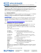
APPLICATION NOTE 3 Using the SUTRON RADAR LEVEL CONTROLLER (RLR-0002-1) with a MULTI-MODEM GPRS (Wireless Modem MTCBA-G-F4) 1. PRODUCT OVERVIEW 1.1 SUTRON RADAR LEVEL RECORDER (RLR-0002-1) The RLR-0002-1 has a front panel that allows a user to setup the operating parameters, monitor performance and perform tests. The RLR-0002-1 is both a sensor and a logger, allowing for stand-alone and integrated applications.
APPLICATION NOTE 4 Using the SUTRON RADAR LEVEL CONTROLLER (RLR-0002-1) with a MULTI-MODEM GPRS (Wireless Modem MTCBA-G-F4) • • • • • • • • • • • • • • • • Short Message Services including text and PDU, point-to-point, cell broadcast 14.4K GSM circuit switched data SMA antenna connector and SIM socket Serial interface supports DTE speeds to 115.2K AT command compatible MNP2 V.
APPLICATION NOTE Using the SUTRON RADAR LEVEL CONTROLLER (RLR-0002-1) with a MULTI-MODEM GPRS (Wireless Modem MTCBA-G-F4) Once the Modem has been activated, it needs to be powered up, hooked up to the antenna, configured and tested. Requirements: • MTCBA-G –F4 Modem • SIM card • RS-232 cable (15 to 9 pin) • Power supply • Antenna • PC running Windows The GSM modem comes with six LEDs indicators in the front panel.
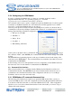
APPLICATION NOTE 6 Using the SUTRON RADAR LEVEL CONTROLLER (RLR-0002-1) with a MULTI-MODEM GPRS (Wireless Modem MTCBA-G-F4) 2.2.4 Configuring the GSM Modem In order to configure the GSM modem, you must use a terminal application such as HyperTerminal in Windows. To open this program, go to: Start>All programs>Accessories>Communications>Hyper Terminal. AT commands can be used to operate, configure and query the GSM modem. A reference guide is included on the Multi-Tech Web site.
APPLICATION NOTE Using the SUTRON RADAR LEVEL CONTROLLER (RLR-0002-1) with a MULTI-MODEM GPRS (Wireless Modem MTCBA-G-F4) AT+VGR=1 AT+VGT=255 AT+CBST=7,0,1 1=Non transparent only) AT+IPR=9600 commands) AT+ICF=3,4 AT+IFC=2,2 AT+FCLASS=0 AT+CSNS=4 ATS0=2 AT&D2 release) AT&C1 ATQ0 AT&W (Use to tune the receive gain of the speakers) (Use to tune the transmit gain of the microphone) (7 = 9600bps, 0 = only asynchronous modem, (Data rate at which the modem will accept (Character framing modem serial port 3= 8
APPLICATION NOTE 8 Using the SUTRON RADAR LEVEL CONTROLLER (RLR-0002-1) with a MULTI-MODEM GPRS (Wireless Modem MTCBA-G-F4) From the factory, the default baud rate setting in the radar level sensor is 115200. The modem baud rate is set to 9600. To change the radar level sensor baud rate, press the down arrow to Station Setup then press the right arrow. Press the down arrow to Other Settings then press the right arrow. Press the down arrow to Baud Rate then select 9600.
APPLICATION NOTE 9 Using the SUTRON RADAR LEVEL CONTROLLER (RLR-0002-1) with a MULTI-MODEM GPRS (Wireless Modem MTCBA-G-F4) +CR:0 +CRC:0 +CMEE:0 +CBST:0,0,1 +SPEAKER:0 +ECHO:0,1 &C:1 &D:2 %C:0 +IPR:9600 +ICF:3,4 +IFC:0,0. 2.4.2 2.4.3 Configuring the Radar – MODBUS The radar (RLR-0002-1) can be configured from the front panel. The following configuration is necessary to use MODBUS interface over GSM modem. 2.4.3.1 Enabling MODBUS Press the down arrow to Station Setup then press the right arrow.
APPLICATION NOTE 10 Using the SUTRON RADAR LEVEL CONTROLLER (RLR-0002-1) with a MULTI-MODEM GPRS (Wireless Modem MTCBA-G-F4) Press the down arrow to Station Setup then press the right arrow. Press the down arrow to Modbus Settings then press the right arrow. Press down arrow to Modbus BaudRate. Clicking the Set button select 9600. 2.4.4 Configuring AutoPoll This section explains how to set up AutoPoll to support MODBUS interface. You have to install AutoPoll program in your PC.
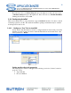
APPLICATION NOTE 11 Using the SUTRON RADAR LEVEL CONTROLLER (RLR-0002-1) with a MULTI-MODEM GPRS (Wireless Modem MTCBA-G-F4) Modem Properties. Clicking the (…) button next to the Type field opens the PC modem properties window. Enter your GSM data phone number. Click Port Settings button. Enter the settings below. Click OK when finished to return to the Task Properties window.
APPLICATION NOTE Using the SUTRON RADAR LEVEL CONTROLLER (RLR-0002-1) with a MULTI-MODEM GPRS (Wireless Modem MTCBA-G-F4) 2.4.4.2 Modbus Master Properties In the Radar Task Properties window, click the (…) button next to the Protocol. The Modbus Master Properties window. Enter the settings below: • Device ID: Should be the same device ID that we select in the radar configuration.
APPLICATION NOTE 13 Using the SUTRON RADAR LEVEL CONTROLLER (RLR-0002-1) with a MULTI-MODEM GPRS (Wireless Modem MTCBA-G-F4) 2.5 2.6 CONNECTING GSM MODEM TO THE RADAR After the radar sensor and GSM modem have been configured, we use the RS-232 interface to connect the radar to the wireless modem using a NULL MODEM CONNECTOR. 2.7 2.8 TESTING MODEM WITH RADAR LEVEL SENSOR 2.8.1 COMMAND-LINE INTERFACE This example will show you how to test GSM modem with the Radar Level Sensor (RLR-00021).
APPLICATION NOTE 14 Using the SUTRON RADAR LEVEL CONTROLLER (RLR-0002-1) with a MULTI-MODEM GPRS (Wireless Modem MTCBA-G-F4) Then, in the Connect To window enter the data GSM modem phone number and click OK. After this, click Dial and you will connected and ready to retrieve data from the RLR-0002-1 sensor. The command prompt symbol (>) will appear in the HyperTerminal window. This shows that you are connected with the GSM modem. In this example we type the HELP command for illustration.
APPLICATION NOTE 15 Using the SUTRON RADAR LEVEL CONTROLLER (RLR-0002-1) with a MULTI-MODEM GPRS (Wireless Modem MTCBA-G-F4) This indicated that your connection with the GSM modem is OK. Then, you can click over this task and then right click to select Run Now. AutoPoll will star to retrieve data (.LOG file) from the Radar Level Recorder sensor. The status field in the AutoPoll window will show you the record number and the total bytes that are downloading.
APPLICATION NOTE 16 Using the SUTRON RADAR LEVEL CONTROLLER (RLR-0002-1) with a MULTI-MODEM GPRS (Wireless Modem MTCBA-G-F4) HI System replies with “Hello” LAST + Shows the last auto measured reading. LOG This command is used to download the log. It can be followed by optional parameters indicating what part of the log to download. LOG with no parameters will download since last. “LOG ALL” gets whole log.
APPLICATION NOTE 17 Using the SUTRON RADAR LEVEL CONTROLLER (RLR-0002-1) with a MULTI-MODEM GPRS (Wireless Modem MTCBA-G-F4) LOG HELP Shows details on how to use the download command. STAGE = 14.5 Changes the current stage to 14.5 (of whatever units are currently chosen). User can choose any number, not just 14.5. Please see the section Setting Stage on page 13. MEAS + Initiates, waits for, and shows the results of sensor measurements. REBOOT Does a software resets of the system.
APPLICATION NOTE Using the SUTRON RADAR LEVEL CONTROLLER (RLR-0002-1) with a MULTI-MODEM GPRS (Wireless Modem MTCBA-G-F4) 18
APPLICATION NOTE 19 Using the SUTRON RADAR LEVEL CONTROLLER (RLR-0002-1) with a MULTI-MODEM GPRS (Wireless Modem MTCBA-G-F4) 4.2 MTCBA-G-F4 (RS-232 15-Pin Connector Pinout) The Wireless Modem has a DE15-serial connector incorporated which includes a RS-232 interface link, audio link, Boot and reset. This connector allows for access to the command line interface using a terminal program such as HyperTerminal of Windows. The following table shows the pin assignment.