
Specifications

APPLICATION NOTE
Using the SUTRON RADAR LEVEL CONTROLLER (RLR-0002-1) with a MULTI-MODEM GPRS
(Wireless Modem MTCBA-G-F4)
17
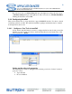
LOG HELP
Shows details on how to use the download command.
STAGE = 14.5
Changes the current stage to 14.5 (of whatever units are currently chosen). User can choose any number,
not just 14.5. Please see the section Setting Stage
on page 13.
MEAS
+
Initiates, waits for, and shows the results of sensor measurements.
REBOOT
Does a software resets of the system.
RESETS + 0
Shows system diagnostics, including system resets. If followed by 0, it will clear system diagnostic status.
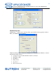
SETUP
If provided without any other parameters, it lists all setup details. That includes each setup variable and its
current value.
Can be followed by a setup variable name and a new value for that variable.
E.g. “CHANGE STATION NAME = SUTRON”
If SETUP DEFAULT is issued, it will reset the entire setup to defaults.
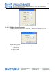
STATUS 0
Shows system status including time, boot time, battery readings, last Radar measurements, current onboard
sensor readings, and any hardware errors that may exist. If followed by 0, it clears the hardware errors.
TIME
Shows the current system date and time. If followed by a new time, it changes the system time.
UPG +
Initiates a system software upgrade. It needs to be followed by the YModem transfer of an .upg file specific
to the product. Both the main application and the bootloader are upgraded this way (but each needs its own
.upg file).
VER +
Shows the current software version, including build date and time and the bootloader version.
4. APPENDIX B : CABLING
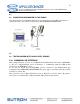
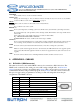
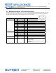
4.1 RLR-0002-1 (DB9 Connector)
The radar level sensor comes with a DB9F connector for connection to RS-232 devices. The
DB9F can be connected to the serial port on most PCs using a straight cable. A null modem
adapter is needed to connect to most PDAs and modems. This connector allows for access to the
command line interface using a terminal program. Some modems and radios can be connected to
this port. A logger can be programmed to use this port. The following table shows the pin
assignments of the DB9F connector.
DB9F Pin Name Notes
1 N/C No Connection
2 RXD Data from Radar
3 TXD Data to the radar
4 DTR Signal to the radar
5 Ground
6 N/C No Connection
7 RTS Request to Send, signal to the radar
8 CTS Clear to Send, signal from the radar
9 VOUT Jumper selectable for 5V or VBAT (100ma max)