
Specifications

APPLICATION NOTE
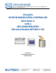
Using the SUTRON RADAR LEVEL CONTROLLER (RLR-0002-1) with a MULTI-MODEM GPRS
(Wireless Modem MTCBA-G-F4)
4
• Short Message Services including text and PDU, point-to-point, cell broadcast
• 14.4K GSM circuit switched data
• SMA antenna connector and SIM socket
• Serial interface supports DTE speeds to 115.2K
• AT command compatible
• MNP2 V.42bis data compression
• Numerous LEDs provide operational status
• ME + SIM phone book management
• Fixed dialing number
• SIM Toolkit Class 2
• SIM, network and service provider locks
• Real time clock
• Alarm management
• UCS2 character set management
• Packet data up to 85K bps
• Embedded TCP/IP stack
NOTE: The purpose of this application note is to focus on the configuration and connection of
the modem using the RS232 interface.
To obtain information about General Specifications of the previous mentioned equipments
access the following web sites.
http://www.sutron.com/products/RadarLevelRecorder.htm
http://www.multitech.com/DOCUMENTS/Collateral/data_sheets/86002084.pdf
2. SETUP AND OPERATION
2.1 Starting the radar level sensor
The radar level sensor starts operating as soon as power is applied. A green blinking LED tells
the user that the radar level sensor is operational. The only way to stop the radar is removing
power from it.
Setting up the radar level sensor via the front panel is one option for setting Time, Baud Rate,
Stage, Enable or Disable Modbus etc. (for more information see RLR-0002-1 User’s manual).
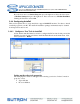
2.2 Starting Multimodem
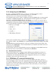
First of all, before we configure the modem, the user will need to activate the modem from a
local service provider with a DATA SERVICE PLAN (Circuit Switch Data). A SIM card will be
provided to the user by the service provider for each device.
IMPORTANT! The modem should have Circuit Switched Data (CSD) enabled from the
wireless carrier.