
Specifications

APPLICATION NOTE
Using the SUTRON RADAR LEVEL CONTROLLER (RLR-0002-1) with a MULTI-MODEM GPRS
(Wireless Modem MTCBA-G-F4)
7
AT+VGR=1 (Use to tune the receive gain of the speakers)
AT+VGT=255 (Use to tune the transmit gain of the microphone)
AT+CBST=7,0,1 (7 = 9600bps, 0 = only asynchronous modem,
1=Non transparent only)
AT+IPR=9600 (Data rate at which the modem will accept
commands)
AT+ICF=3,4 (Character framing modem serial port 3= 8 Data 1 stop, 4=
None)
AT+IFC=2,2 (Hardware flow control mode 2= RTS, 2= CTS)
AT+FCLASS=0 (0 = Data operating mode)
AT+CSNS=4 (Select de bearer 4=data)
ATS0=2 (Numbers of rings before automatic answer)
AT&D2 (Upon DTR switch from ON to OFF, the call id
release)
AT&C1 (Controls Data Carrier Detect Signal (DCD) )
ATQ0 (0 = Modem transmit result codes)
AT&W (Save configuration)
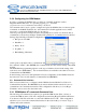
After all programming is done; you can use “AT&V” command to verify the modem
configuration. This should show:
AT&V
Q:0 V:1 S0:002 S2:043 S3:013 S4:010 S5:008
+CR:0 +CRC:0 +CMEE:0 +CBST:7,0,1
+SPEAKER:0 +ECHO:0,1 &C:1 &D:2 %C:0
+IPR:9600 +ICF:3,4 +IFC:2,2
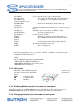
2.3.2 LED status.
The LEDs on the GSM modem front panel tell you
the status of the modem. The LEDs should be as
follow:
PWR Continuous ON
TR Continuous ON
LS Flashing
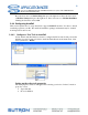
2.3.3 Disabling Modbus mode in the radar via front panel
Press the down arrow to Station Setup then press the right arrow. Press the down arrow to
Modbus Settings then press the right arrow. Clicking the Set button select Disable.
2.3.4 Changing the baud rate in the radar via front panel