MultiVOIP® Voice/Fax over IP Gateways MVP210/410/810 MVP210/410/810‐SS MVP210/410/810‐FX User Guide
User Guide S000383E Analog MultiVOIP Units (Models MVP210, MVP410, MVP810) (Models MVP210‐SS, MVP410‐SS, MVP810‐SS) (Models MVP210‐FX, MVP410‐FX, MVP810‐FX) Upgrade Unit (Model MVP428) This publication may not be reproduced, in whole or in part, without prior expressed written permission from Multi‐Tech Systems, Inc. All rights reserved. Copyright © 2011, by Multi‐Tech Systems, Inc. Multi‐Tech Systems, Inc.
Contents Chapter 1 – Product Overview.......................................................................................................................... 6 Feature Comparison Table ............................................................................................................................................ 6 Interfaces to Help You Use the MultiVOIP ....................................................................................................................
Contents Configuring Interface Parameters ............................................................................................................................... 44 Call Signaling ................................................................................................................................................................ 57 Configuring SNMP ...............................................................................................................................................
Contents Implementing a Software Upgrade ........................................................................................................................... 125 Downloading IFM Firmware ...................................................................................................................................... 128 Setting and Downloading User Defaults .................................................................................................................... 130 Setting a Password .
Chapter 1 – Product Overview The MultiVOIP gateways, MVP210, MVP410, and MVP810 provide toll‐free voice and fax communications over the Internet or an Intranet. By integrating voice and fax into your existing data network, you can substantially save on inter‐office long distance toll charges. MultiVOIP gateways connect directly to phones, fax machines, key systems, PSTN lines, or a PBX to provide real‐time, toll‐quality voice connections to any office on your VOIP network.
Chapter 1 – Product Overview Interfaces to Help You Use the MultiVOIP Two interfaces help you use your MultiVOIP: ● A web interface ● Windows software interface The web interface and the Windows interface share content and organizational attributes. However, each interface has different logging capabilities. Overview of Front Panel LEDs Eight sets of channel‐operation LEDs appear on both the MVP410 and MVP810 models.
Chapter 1 – Product Overview Computer Requirements The computer on which the MultiVOIP’s configuration program is installed must meet these requirements: ● IBM‐compatible PC with MS Windows operating system ● Have an available COM port for connection to the MultiVOIP The computer does not need to be connected to the MultiVOIP permanently. It only needs to be connected when local configuration and monitoring are done. You can perform configuration and monitoring remotely through the IP network.
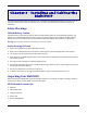
Chapter 2 – Installing and Cabling the MultiVOIP The MVP210 MultiVOIP models are tabletop units. The MVP410 and MVP810 MultiVOIPs are heavier units. As such two or more people need to install these units into racks. Read the safety notices before beginning installation. Safety Warnings Lithium Battery Caution A lithium battery on the voice/fax channel board provides backup power for the timekeeping capability. The battery has an estimated life expectancy of ten years.
Chapter 2 – Installing and Cabling the MultiVOIP MVP410/810 models content list ● MVP410 or MVP810 ● DB9 to DB25 cable ● Mounting brackets and screws ● Power cord ● Printed Cabling Guide Mounting MVP410 and MVP810 in Racks You can mount the MultiVOIPs in an industry‐standard EIA 19‐inch rack enclosure.
Chapter 2 – Installing and Cabling the MultiVOIP Connecting the MVP210 to LAN and Telephone Equipment To connect the MultiVOIP unit to your LAN and telephone equipment: 1. Connect the power cord supplied with your MultiVOIP to the power connector on the back of the MultiVOIP and to a live AC outlet as shown in the figure that follows. Note: The –SS and –FX models do not have the E&M jacks as shown. 2. Connect the MultiVOIP to a PC by using a RJ‐45 (male) to DB‐9 (female) cable.
Chapter 2 – Installing and Cabling the MultiVOIP c. For a DID connection. (DID Example: DID fax system or DID voice phone lines) Connect one end of an RJ‐11 phone cord to the Channel 1 FXS/FXO connector on the back of the MultiVOIP. Connect the other end to the DID jack. Note: DID lines are polarity sensitive. If the DID line rings busy consistently during testing, you need to reverse the polarity of one end of the connector (swap the wires to the two middle pins of one RJ‐11 connector). 4.
Chapter 2 – Installing and Cabling the MultiVOIP For DID channels only For any channel on which you are using the DID interface type, you must change the jumper on the MultiVOIP circuit card. DID is not supported on the –SS or –FX models. 1. Disconnect power. Unplug the AC power cord from the wall outlet or from the receptacle on the MultiVOIP unit. 2.
Chapter 2 – Installing and Cabling the MultiVOIP Connecting MultiVOIP to LAN and Telephone Equipment (MVP410/810) To connect the MultiVOIP to your LAN and telephone equipment.: 1. Connect the power cord supplied with your MultiVOIP to a live AC outlet and to the power connector on the back of the MultiVOIP as shown at top right in the figure that follows. The E&M jacks are not present on the –SS and –FX models.
Chapter 2 – Installing and Cabling the MultiVOIP c. For a DID connection. (DID Examples: DID fax system or DID voice phone lines.) Connect one end of an RJ‐11 phone cord to the Channel 1 FXS/FXO connector on the back of the MultiVOIP. Connect the other end to the DID jack. Note: DID lines are polarity sensitive.
Chapter 2 – Installing and Cabling the MultiVOIP 3. Pull the main circuit card out about 5 inches (the power connection to the board prevents it from being removed entirely from the chassis). 4. Identify the channels on which the DID interface is used. 5. Position the jumper for each DID channel so that it does not connect the two jumper posts.
Chapter 3 – Installing Software Setting up your MultiVOIP involves the following tasks: 1. Install the software onto the PC. This step is described in further detail in this chapter. 2. Set values for telephony and IP parameters appropriate for your system. This step is described in detail in Chapter 4. 3. Define phone books that contain the dialing patterns for VOIP calls made to different locations. This step is described in greater detail in Chapter 5.
Chapter 3 – Installing Software 6. 18 Select a program folder location for the MultiVOIP software program icon. Click Next. Progress windows appear while files are being copied.
Chapter 3 – Installing Software 7. In the next wizard panel, select the COM port that the command PC uses when communicating with the MultiVOIP unit. After you install the software, you can re‐set the COM port using the MultiVOIP Software. To do so, from the sidebar menu, select Connection | Settings. Or use keyboard shortcut Ctrl + G.
Chapter 3 – Installing Software Configuring for VOIP Communications This section describes how to configure the MultiVOIP so you can use VOIP communications. ● Ethernet/IP ● Voice/Fax ● Interface ● Call Signaling ● Regional ● Phone Book This setup process is followed by an important Save & Reboot step. Other chapters in this guide describe configuration in detail.
Chapter 3 – Installing Software Setting IP Address For basic operation of the unit, you must set a unique LAN IP address as well as a subnet mask and Gateway IP. Other settings control specific features and protocols. These settings are not necessary for basic operation. Chapter 4 describes all settings. To configure IP settings: 1. If you are using packet prioritization: a. Check Packet Prioritization. b. Set 802.1p Priority Parameters as needed.
Chapter 3 – Installing Software 9. Enter DNS Server IP Address 10. If desired, check the Enable SRV checkbox. 11. The Diff Serv Parameters group helps you specify settings for routers that are Diff Serv compatible Setting both values to 0 effectively disables Diff Serv. 12. FTP Server Enable is only needed for firmware and software updates to the MultiVOIP. 13. If desired, check the TDM Routing checkbox.
Chapter 3 – Installing Software Setting Voice/Fax Parameters You must configure the individual channels before using your unit. If channels have the same parameters, you can use the Copy Channel button to save time. You can note some options for future changes if necessary, but default settings likely work, without adjustment.
Chapter 3 – Installing Software To configure channels: 1. From the Select Channel drop‐down list, select the channel you want to configure. 2. In the Fax/Modem Parameters group: a. From the Set Max Baud Rate drop‐down list, select a rate that matches a fax machine (2400 to 14400 bps). b. Do not change the setting in the Fax Volume drop‐down menu. Such changes can adversely impact the modem’s operation. c. From the Jitter Value drop‐down list, select the desired time for packet reassembly. d.
Chapter 3 – Installing Software Setting Interface Parameters The Interface parameters control the telephony settings that are applied to the individual MultiVOIP channels. Configure each channel for the type of interface you are using. Channel 1 is selected by default. Note: Features are available or unavailable depending on the selected interface type. The one option available for all interface types is the inter digit timer option.
Chapter 3 – Installing Software To set Interface Parameters: 1. From the Channel drop down list, select Channel whose parameters you want to configure. 2. From the Interface Type drop down list, select FXS, FXO, E&M or DID (FXS/FXO only for –SS and –FX series) 3. From the Regeneration group, select how signal is regenerated; as Pulse or DTMF 4. In the Inter Digit Timer field, type time the MultiVOIP waits between digits. 5.
Chapter 3 – Installing Software b. Complete Disconnect fields: 12.
Chapter 3 – Installing Software Setting Call Signaling There are three choices for Call Signaling: H.323, SIP and SPP, the –SS models only support SIP and the –FX models support SIP and SPP, but not H.323. It is best to select one of these as the protocol to be used, rather than mixing them. Single Port Protocol (SPP) is a non‐standard protocol created by Multi‐Tech that allows dynamic IP allocation. Generally, the default settings do not work for most users.
Chapter 3 – Installing Software Configuring H.323 Call Signal This feature is not supported by –SS and –FX series. 1. Check Fast Start, as this may be needed for third‐party vendor compatibility. 2. In the Signaling Port field, type a port number. The default is 1720. 3. If a gatekeeper is to control VOIP check Register with Gatekeeper. 4. Check Allow Incoming Calls Through Gatekeeper Only. 5. In the Gatekeeper RAS Parameters group, set the following: a.
Chapter 3 – Installing Software Setting the Region or Country Select the country or region in which the MultiVOIP unit operates. Use the custom option if the available settings are not adequate. 1. From the Country/Region drop‐down list, select the location of the MultiVOIP. 2. If no location fits your needs, select Custom and set the tones manually. To create user‐defined tones to be used with FXO Supervision, click Add.
Chapter 3 – Installing Software Defining the Phone Book A populated phone book helps the VOIP unit translate call traffic. You need the information for both a local site and any remote sites. Chapter 5 provides detailed descriptions and examples.
Chapter 3 – Installing Software Configuring the Outbound Phone Book 1. Select Add Entry. 2. To allow unmatched destinations an alternative, check Accept Any Number. 3. In the Destination Pattern field, type the number necessary to get out from the PBX system followed by the calling code of the destination 4. In the Remove Prefix field, type the PBX access digit. This is the same number as needed to get out of the PBX system. 5. In the Add Prefix field, type other needed digits. 6.
Chapter 4 – Configuring Your MultiVOIP Two interfaces help you use your MultiVOIP: ● A web interface ● Windows software interface You must set eight parameters for proper MultiVOIP operation. You must know the IP address used, the IP mask, the Gateway IP, the Domain Name Server information, and the telephone interface type. Initially, you must configure the MultiVOIP locally. To do so, use a connection between the command port of the MultiVOIP and the COM port of the computer.
Chapter 4 – Configuring Your MultiVOIP Navigating the Software To launch the MultiVOIP software: 1. From the Start button, select All Programs, MultiVOIP x.xx, where x represents version number. 2. Select Configuration.
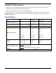
Chapter 4 – Configuring Your MultiVOIP Configuration Information Checklist The following chart helps you organize the configuration information needed. The –SS and –FX models do not support E&M or DID. Type of Configuration Info Gathered: IP info for VOIP unit Configuration window where info is entered: Info Info Obtained? Entered? D D Ethernet/IP parameters • IP address • Gateway • DNS IP (if used) • 802.
Chapter 4 – Configuring Your MultiVOIP Setting Ethernet/IP This section describes the Ethernet settings needed for the MultiVOIP unit. In each field, enter the values that fit the network to which the MultiVOIP is connected. For many settings, the default values work best. Try these settings first unless you are certain that you need to change a parameter. The Ethernet/IP Parameters fields are described in the tables that follow.
Chapter 4 – Configuring Your MultiVOIP Ethernet/IP Parameter Definitions Field Name Values Description Ethernet Parameters Packet Prioritization Y/N Select to activate prioritization under 802.1p protocol (described below). (802.1p) Frame Type Type II, SNAP Must be set to match network’s frame type. Default is Type II. 802.1p A draft standard of the IEEE about data traffic prioritization on Ethernet networks. The 802.1p draft is an extension of the 802.1D bridging standard. 802.
Chapter 4 – Configuring Your MultiVOIP Ethernet/IP Parameter Definitions (continued) Field Name Values Description Diff Serv Parameter fields Diff Serv PHB (Per Hop Behavior) values pertain to a differential prioritizing system for IP packets as handled by Diff Serv‐compatible routers. There are 64 values, each with an elaborate technical description.
Chapter 4 – Configuring Your MultiVOIP Setting Voice/Fax Parameters Configure the Voice/Fax section for each channel used. For convenience, after you have established a set of Voice/FAX parameters for a particular channel, you can apply this entire set of Voice/FAX parameters to another channel by using the Copy Channel button and its dialog box. To copy a set of Voice/FAX parameters to all channels, select Copy to All and click Copy.
Chapter 4 – Configuring Your MultiVOIP Voice/Fax Parameter Definitions Field Name Default Select Channel Copy Channel Voice Gain Input Gain Output Gain DTMF Gain Values ‐‐ 1‐2 (210) 1‐4 (410) 1‐8 (810) ‐‐ ‐‐ +31dB to –31dB +31dB to –31dB ‐‐ DTMF Gain, High Tones +3dB to ‐31dB & “mute” DTMF Gain, Low +3dB to Tones ‐31dB & “mute” DTMF Parameters Duration (DTMF) DTMF In/Out of Band Out of Band Mode 60 – 3000 ms Out of Band, or Inband RFC 2833, SIP Info Description When this button is clicked, all Voice/F
Chapter 4 – Configuring Your MultiVOIP Voice/Fax Parameter Definitions (continued) Coder Coder Parameters Manual or Automatic Selected Coder (SS models only) G.711 a/u law 64 kbps; G.726, @ 16/24/32/40 kbps; G.727, @ nine bps rates; G.723.1 @ 5.3 kbps, 6.3 kbps; G.729, 8kbps; Net Coder @ 6.4, 7.2, 8, 8.8, 9.6 kbps Selected Coder G.711, G.729 ‐or‐ G.729, G.711 Max bandwidth (coder) 11 – 128 kbps Determines whether selection of coder is manual or automatic.
Chapter 4 – Configuring Your MultiVOIP Voice/Fax Parameter Definitions (continued) Field Name Values Description AutoCall/Offhook Alert Parameters Auto Call / Offhook Alert AutoCall, Offhook Alert The AutoCall option enables the local MultiVOIP to call a remote MultiVOIP without the user having to dial a Phone Directory Database number.
Chapter 4 – Configuring Your MultiVOIP Voice/Fax Parameter Definitions (continued) Field Name Values Dynamic Jitter Dynamic Jitter Buffer Minimum Jitter Value 60 to 400 ms Maximum Jitter Value 60 to 400 ms Optimization Factor 0 to 12 Description Dynamic Jitter defines a minimum and a maximum jitter value for voice communications. When receiving voice packets from a remote MultiVOIP, varying delays between packets may occur due to network traffic problems. This is called Jitter.
Chapter 4 – Configuring Your MultiVOIP When interoperating with older MultiVOIP products (that is, earlier than release x.11), for backward compatibility, configure the payload type values to default ones, which match the values of older MultiVOIPs. Configuring Interface Parameters Set the Telephony Interface parameters individually for each channel and include the line types as well as some specific situational settings when required.
Chapter 4 – Configuring Your MultiVOIP Configuring FXS Loop Start Parameters The figure and table that follow describe the parameters applicable to FXS Loop Start. FXS Loop Start Interface: Parameter Definitions Field Name Values Dialing Options fields FXS (Loop Start) Y/N Description Inter Digit Timer This is the length of time that the MultiVOIP waits between digits. When the time expires, the MultiVOIP looks in the outbound phonebook for the number entered and place the call accordingly.
Chapter 4 – Configuring Your MultiVOIP FXS Loop Start Interface: Parameter Definitions (continued) Field Name Values Description Flash Hook Options fields Generation ‐‐ Not applicable to FXS interface Detection Range for Min. and Max.
Chapter 4 – Configuring Your MultiVOIP Configuring Message Waiting The Message Waiting Indication feature provides an audible or visible indication that a message is available. A type of message waiting is sounding a special dial tone (called stutter dial tone), lighting a light, or indicator on the phone. When a user enables a subscription for message waiting indication, a subscription is made with the Voice Mail Server (VMS) for that particular event.
Chapter 4 – Configuring Your MultiVOIP ● The Channel type corresponding to that Inbound phone book entry has to be FXS on the Interface window. ● The Message Waiting Indication has to be either Light or Stutter Dial Tone on the Interface Parameters window. The password on the Interface window is used for that particular channel when a “SUBSCRIBE” request is sent; that is, if the MultiVOIP gets a 401/407 response from a subscribe request.
Chapter 4 – Configuring Your MultiVOIP FXO Interface: Parameter Definitions Field Name Values Description Interface Type FXO Enables FXO features. Dialing Options Regeneration Pulse, DTMF Determines whether digits generated and sent out are pulse tones or DTMF. Inter Digit Timer 1 to 10 seconds This is the length of time that the MultiVOIP waits between digits. When the time expires, the MultiVOIP looks in the phonebook for the number entered. Default = 2.
Chapter 4 – Configuring Your MultiVOIP FXO Supervision When the selected Interface type is FXO, the Supervision button is active. Click Supervision to access call answering supervision parameters and call disconnection parameters that relate to the FXO interface type. The table that follows describes the settings for FXO Supervision.
Chapter 4 – Configuring Your MultiVOIP FXO Supervision Parameter Definitions Field Name Values Answer Supervision fields Current Reversal Y/N Answer Delay Y/N Answer Delay Timer Tone Detection 1 – 65535 (in seconds) Y/N Available Tones dial tone, ring tone, busy tone, unobtainable tone (fast busy), survivability tone, re‐order tone Answer Tones any tone from Available Tones list Disconnect Supervision fields Description When this option is selected, the FXO interface sends notice to make connection
Chapter 4 – Configuring Your MultiVOIP FXO Supervision Parameter Definitions (continued) Field Name Values Disconnect Supervision fields DTMF Tone Description Enables supervision of call disconnection using DTMF tones. DTMF Tone Pairs 1 4 7 * 1209Hz High Tones Disconnect Tone Sequence 1st tone pair + nd 2 tone pair 2 5 8 0 1336Hz 3 6 9 # 1447Hz A B C D 1633Hz Low Tones 697Hz 770Hz 852Hz 941Hz These are DTMF tone pairs. Values for first tone pair are: *, #, 0, 1‐9, and A‐D.
Chapter 4 – Configuring Your MultiVOIP E&M Parameters The parameters applicable to the E&M telephony interface type are shown in the figure and described in the table that follows. Analog MVP210/410/810 models support the E&M interface. ‐SS and ‐FX models do not.
Chapter 4 – Configuring Your MultiVOIP E&M Interface Parameter Definitions Field Name Values Description Interface E&M Enables E&M features Type I–V Mode 2‐wire or 4‐wire Type of E&M interface being used – the individual types are detailed below. Default = Type II. Each E&M interface type can be either 2‐wire or 4‐wire audio. Signal Dial Tone or Wink Wink Timer 100 ‐ 350 milliseconds When Dial Tone is selected, no wink is required on the E lead or M lead in the call initiation or setup.
Chapter 4 – Configuring Your MultiVOIP E&M Interface Types There are five different types of the E&M interface and the MVP210/410/810 models support them all; but Type IV is largely unused and is not described in this section. The figures that follow show the pin assignments for the MVP RJ48 connector when used in the E&M jacks on the back of the unit as well as how the signals are used for types one, two, three and five.
Chapter 4 – Configuring Your MultiVOIP DID Parameters The parameters applicable to the Direct Inward Dial (DID) telephony interface type are shown in the figure that follows and described in the table that follows. The –SS and –FX models do not support DID. The DID interface allows one phone line to direct incoming calls to any one of several extensions without a switchboard operator. Of course, one DID line can handle only one call at a time.
Chapter 4 – Configuring Your MultiVOIP Call Signaling Three types of Call Signaling are available: H.323, SIP and SPP. Each type has features that may make it more appealing to use than the others, depending on your needs. The –SS and –FX models do not support H.323 signaling. H.323 H.323 is an ITU‐T recommended set of standards for audio and video communications. The fields for this window are defined in the table below.
Chapter 4 – Configuring Your MultiVOIP H.323 Call Signaling Parameter Definitions. Field Name Values Description Use Fast Start Y/N Enables the H.323 Fast Start procedure. May need to be enabled/disabled for compatibility with third‐party VOIP gateways. Signaling Port port Default: 1720 (H.323) Register with Gatekeeper Y/N Check this field to have traffic on current VOIP gateway controlled by a gatekeeper.
Chapter 4 – Configuring Your MultiVOIP SIP Session Initiation Protocol is available for application layer control of the MultiVOIP. The fields are detailed in the table that follows.
Chapter 4 – Configuring Your MultiVOIP SIP Call Signaling Parameter Definitions Field Name Values Description SIP Proxy Parameters Signaling Port port Port number on which the MultiVOIP UserAgent software module is waiting for any incoming SIP requests. Default = 5060 Use SIP Proxy Y/N Allows the MultiVOIP to work in conjunction with a proxy server. Allow Incoming Calls Through SIP Proxy Only Y/N When selected, incoming calls are accepted only if those calls come through the proxy.
Chapter 4 – Configuring Your MultiVOIP Configuring SIP Server The MultiVOIP 210/410/810‐SS models have the additional capability of SIP survivability. This section describes the settings for SIP server mode.
Chapter 4 – Configuring Your MultiVOIP addresses for private networks not accessible via Internet or PSTN. IP Addresses n.n.n.n List of IP addresses (separated by semicolon) of endpoints from which the MVP‐SS accepts registrations. Re‐Registration Time in seconds; (default is 3600) The time after which the UserAgent Client registers with the proxy server. Expired registration indicates the gateway lost contact with the main SIP server and that the MVP‐SS unit enters ‘survivability’ mode.
Chapter 4 – Configuring Your MultiVOIP SIP Server Predefined Endpoints Parameter Definitions Field Name Values Description Identifier for gateway within SIP VOIP system. Maximum length is 33 Endpoint Name name characters. Password password This password is for authentication of gateway to SIP server. Registration Type Static, Dynamic Static registrations are fixed and the contact information for them is configured by the user and not subject to removal from the registration list due to timeouts.
Chapter 4 – Configuring Your MultiVOIP SPP Multi‐Tech developed Single Port Protocol for dynamic IP addressing when the feature is set to Registrar/Client mode. The other setting, Direct mode, has IP addresses assigned to the gateways. The table below describes fields in the general SPP Call Signaling window. The –SS models do not support SPP.
Chapter 4 – Configuring Your MultiVOIP SPP Call Signaling Parameter Definitions Field Name Values Description Mode Direct, Client, or Registrar In direct mode, all VOIP gateways have static IP addresses assigned to them. In registrar/client mode, one VOIP gateway serves as registrar and all other gateways, being its clients, point to that registrar. The registrar assigns IP addresses dynamically. General Options Port port The UDP port on which data transmission occurs.
Chapter 4 – Configuring Your MultiVOIP Configuring SNMP If you want to manage your MultiVOIP remotely using the MultiVoipManager software, set the Simple Network Management Protocol parameters. To make the MultiVOIP controllable by a remote PC running the MultiVoipManager software, check the Enable SNMP Agent checkbox on the SNMP Parameters window. The –SS and –FX series MultiVOIPs have limited SNMP functions available.
Chapter 4 – Configuring Your MultiVOIP Configuring Regional Parameters Use the Regional Parameters to set the phone signaling tones and cadences. For the country selected, the standard set of frequency pairs is listed for dial tone, busy tone, ‘unobtainable’ tone (fast busy or trunk busy), ring tone, and other, more specialized tones. If desired settings are not available, use the Custom selection to set the tones as needed. The table that follows describes the Regional Parameters fields.
Chapter 4 – Configuring Your MultiVOIP “Regional Parameter” Definitions Field Name Values Description Country/Region USA, Japan, UK, Custom Name of a country or region that uses a certain set of tone pairs for dial tone, ring tone, busy tone, unobtainable tone (fast busy tone), survivability tone (tone heard briefly, 2 seconds, after going off hook denoting survivable mode of VOIP unit), re‐order tone (a tone pattern indicating the need for the user to hang up the phone), and intercept tone (a tone tha
Chapter 4 – Configuring Your MultiVOIP “Regional Parameter” Definitions (continued) Field Name Country Selection for Built‐In Modem (not applicable to MVP210) Values country name User Defined Tones fields Type column alphanumeric name Frequency 1 Freq. in Hertz Frequency 2 Freq.
Chapter 4 – Configuring Your MultiVOIP Setting Custom Tones and Cadences (optional). A secondary dialog box allows you to customize DTMF tone pairs to create unique ring‐tones, dial‐tones, busy‐tones or “unobtainable” tones or “re‐order” tones or “survivability” tones. This helps the user to specify tone‐pair attributes that are not found in any of the standard national/regional telephony toning schemes. To customize DTMF tone pairs, click Custom.
Chapter 4 – Configuring Your MultiVOIP Configuring SMTP Parameters Setting the SMTP Parameters (Log Reports by Email). Use the SMTP Parameters window for configuring how log reports are handled by email. Email Address for VOIP (for email call log reporting) This is needed only if log reports of VOIP call traffic are sent by email. ● Ask Mail Server administrator to set up email account (with password) for the MultiVOIP unit. ● Supply a unique identifier to each MultiVOIP unit.
Chapter 4 – Configuring Your MultiVOIP “SMTP Parameters” Definitions Field Name Values Description Enable SMTP Y/N To send log reports by email, enable this checkbox. To enable the SMTP feature, you must also select “SMTP” in the Logs window. Requires Authentication Y/N If checked, the MultiVOIP sends Authentication information to the SMTP server. The authentication information indicates if the email sender has permission to use the SMTP server.
Chapter 4 – Configuring Your MultiVOIP Click Select Fields to open the SMTP Parameters dialog box. This secondary dialog box helps you customize email logging. The MultiVOIP software logs data about aspects of the call traffic going through the MultiVOIP. The Custom Fields window lets you pick which items are included in the email log reports. “Custom Fields” Definitions Field Description Field Description Select All Log report to include all fields shown.
Chapter 4 – Configuring Your MultiVOIP RADIUS In general, RADIUS is concerned with authentication, authorization, and accounting. The MultiVOIP supports the accounting and authentication functions. The accounting function is well suited for billing of VOIP telephony services. In the Select Attributes secondary window (accessed by clicking on Select Attributes button), you can select the parameters that the RADIUS server tallies.
Chapter 4 – Configuring Your MultiVOIP The table that follows describes the fields of the RADIUS window. RADIUS Window Field Definitions Field Name Values Description Enable Accounting Y/N When checked, the MultiVOIP accesses the accounting functions of the RADIUS server. Server Address n.n.n.n IP address of the RADIUS server that handles accounting (billing) for the current MultiVOIP unit.
Chapter 4 – Configuring Your MultiVOIP Logs/Traces The Logs/Traces window lets you choose how the VOIP administrator receives log reports about the MultiVOIP’s performance and the phone call traffic that is passing through it. The VOIP administrator receives log reports in one of three ways: ● In the MultiVOIP program (interface) ● Through email (SMTP) ● At the MultiVoipManager remote VOIP system management program (SNMP).
Chapter 4 – Configuring Your MultiVOIP NAT Traversal Setting the NAT Traversal parameters. NAT (Network Address Translation) parameters are applicable only when the MultiVOIP is operating in SIP mode. STUN (Simple Traversal of UDP through NATs (Network Address Translation)) is a protocol for assisting devices behind a NAT firewall or router with their packet routing. This is not available on the –SS models. The following table describes NAT Traversal fields.
Chapter 4 – Configuring Your MultiVOIP Supplementary Services Supplementary Services features derive from the H.450 standard, which brings to the VOIP telephony functions once only available with PSTN or PBX telephony. Even though the H.450 standard refers only to H.323, Supplementary Services are still applicable to the SIP and SPP VOIP protocols. Three of the features implemented under Supplementary Services are closely related. ● Call Transfer.
Chapter 4 – Configuring Your MultiVOIP The table that follows describes the Supplementary Services fields. Supplementary Services Parameter Definitions Field Name Values Description Select Channel 1‐2 (210); 1‐4 (410); 1‐8 (810) The channel to be configured is selected here. Call Transfer Enable Y/N Select to enable the Call Transfer function in the VOIP unit. This is a “blind” transfer and the sequence of events is as follows: Callers A and B are having a conversation.
Chapter 4 – Configuring Your MultiVOIP Supplementary Services Definitions (continued) Field Name Description Calling Party, Allowed Name Type (CNI) If the ‘home’ VOIP unit is originating the call and Calling Party is selected, then the identifier (from the Caller Id field) is sent to the remote VOIP unit being called. The Caller Id field gives the remote VOIP administrator a plain‐language identifier of the party that is originating the call occurring on a specific channel.
Chapter 4 – Configuring Your MultiVOIP Save Settings Save & Reboot Saving the MultiVOIP Configuration. When values have been set for all of the MultiVOIP’s various operating parameters, click Save Setup in the sidebar, then Save & Reboot. Creating a User Default Configuration. When a “Setup” (complete grouping of parameters) is being saved, you are prompted about designating that setup as a “User Default” setup.
Chapter 4 – Configuring Your MultiVOIP Troubleshooting Software Issues In the lower left corner of the window, the connection status of the MultiVOIP appear. The messages in the lower left corner change as detection occurs. The message “MultiVOIP Found” confirms that the MultiVOIP is in contact with the MultiVOIP configuration program. If the message displayed is “MultiVOIP Not Found!” please try the resolutions that follow.
Chapter 5 – Configuring the Phone Book When a VOIP serves a PBX system, ensure that the VOIP’s operation is transparent to the telephone end user. Make sure the VOIP does not dial extra digits to reach users elsewhere on the network that the VOIP serves. VOIP service commonly reduces dialed digits. This allows users (served by PBXs in facilities in distant cities) to dial their co‐workers with 3‐, 4‐, or 5‐digit extensions as if they were in the same facility.
Chapter 5 – Configuring the Phone Book Initially Configuring the Phonebook This section describes setting up the phone book. It provides examples that help you enter the correct numbers for proper MultiVOIP operation. Initially, you set up two VOIP locations and establish VOIP communication. Once this is accomplished, you can easily add other VOIP sites to the network. Before You Begin Before you configure the phone book: ● Obtain access to another VOIP that you can call for testing.
Chapter 5 – Configuring the Phone Book 5. In the Destination Pattern field of the Add/Edit Outbound Phonebook window, enter the digits from step 4 followed by the digits from step 3. North America, Long‐Distance Example Seattle/Chicago system. Answer: enter 81312 as Destination Pat‐tern in Outbound Phone‐book of Seattle VOIP. 6. Euro, National Call Example Euro, International Call Example London/Birmingham system.
Chapter 5 – Configuring the Phone Book Configuring the Inbound Phonebook 1. Open the MultiVOIP program. (Start | MultiVOIP xxx | Configuration) 2. Go to Phone Book | Inbound Phonebook | Add Entry. 3. In the Remove Prefix field, type the local calling code (area code, country code, city code, and so on) preceded by any other access digits that are required to reach your local site from the remote VOIP location. Think of it as though the call were being made through the PSTN – even though it is not.
Chapter 5 – Configuring the Phone Book Phone Book Descriptions Outbound Phone Book/List Entries Fields in the Details group differ depending on the protocol (H.323, SIP, or SPP) associated with the selected list entry.
Chapter 5 – Configuring the Phone Book Add/Edit Outbound Phone Book Enter Outbound Phone Book data for your MultiVOIP unit. Note that the Advanced button gives access to the Alternate IP Routing feature, if needed. Alternate IP Routing can be implemented in a secondary window (as described after the primary window field definitions below). The –SS only allows SIP settings and the –FX models do not allow H.323. The table that follows describes the fields of the Add/Edit Outbound Phone Book window.
Chapter 5 – Configuring the Phone Book Add/Edit Outbound Phone Book: Field Definitions Field Name Values Description Accept Any Number Y/N When checked, “Any Number” appears as the value in the Destination Pattern field. The Any Number feature works differently depending on whether or not an external routing device is used (Gatekeeper for H323 protocol, Proxy for SIP protocol, Registrar for SPP protocol). When no external routing device is used.
Chapter 5 – Configuring the Phone Book Add/Edit Outbound Phone Book: Field Definitions (continued) Field Name Values Description SIP Fields Use Proxy Y/N Select if proxy server is used. Transport Protocol TCP or VOIP administrator must choose between UDP and TCP transmission protocols. UDP is a high‐speed, low‐overhead connectionless protocol where data is transmitted without acknowledgment, guaranteed delivery, or guaranteed packet sequence integrity.
Chapter 5 – Configuring the Phone Book Configuring Alternate Routing Alternate routing provides an alternate path for calls if the primary IP network cannot carry the traffic. Sometimes during failure, call traffic is temporarily diverted into the PSTN. However, you also use alternate routing to divert traffic to a redundant (backup) unit in case one VOIP unit fails. Alternate routing facilitates PSTN Failover protection.
Chapter 5 – Configuring the Phone Book PSTN Failover Feature. You can program the MultiVOIP to divert calls to the PSTN temporarily if the IP network fails. The following figure provides an example. 3. Call diverts to Alt IP address in voip accessing PSTN line. 4. Call completed via PSTN. PSTN Line FXO VOIP FXS IP NETWORK VOIP 2. IP network fails. PBX 1. Call originates.
Chapter 5 – Configuring the Phone Book Add/Edit Inbound Phone Book MultiVOIP® Voice/Fax over IP Gateways 93
Chapter 5 – Configuring the Phone Book Enter Inbound Phone Book data for your MultiVOIP. The table that follows describes the Add/Edit Inbound Phone Book window. Add/Edit Inbound Phone Book: Field Definitions Field Name Values Description Accept Any Number Y/N When checked, “Any Number” appears as the value in the Remove Prefix field. The Any Number feature of the Inbound Phone Book does not work when an external routing device is used (Gatekeeper for H.
Chapter 5 – Configuring the Phone Book Authorized User Name and Password for SIP To enable the Registration Options on the Add/Edit Inbound Phone Book, activate Use SIP Proxy Option on the Call Signaling, SIP Parameters Window. Then add the IP address for the Primary Proxy in the SIP Proxy Parameters. This allows you to add a Username and Password to the Inbound Phone Book entry. The –SS models only have a password option available.
Chapter 5 – Configuring the Phone Book Phonebook Examples North America This section describes how Outbound and Inbound Phonebook entries work with multiple area codes. This example uses a company with offices in Minneapolis and Baltimore. The local calling area of Minneapolis consists of multiple adjacent area codes. Baltimore’s local calling area consists of a base area code plus an overlay area code. Company VOIP/PBX SIte NW Suburbs 763 5 Mpls 612 SW Suburbs 952 St. Paul & Suburbs 651 ...
Chapter 5 – Configuring the Phone Book The figure that follows shows Outbound Phonebook entries for the VOIP located in the company’s Baltimore facility. The entries in the Minneapolis VOIP’s Inbound Phonebook match the Outbound Phonebook entries of the Baltimore VOIP, as shown below. To call the Minneapolis/St. Paul area, a Baltimore employee must dial eleven digits. This assumes that the Baltimore PBX does not require an 8 or 9 to seize an outside phone line.
Chapter 5 – Configuring the Phone Book The simplest case is a call from Baltimore to a phone within the Minneapolis/St. Paul area code where the company’s VOIP and PBX are located, namely 763. Here, the local VOIP removes 1763 and dials 9 to direct the call to its local 7‐digit PSTN. Finally, consider the longest entry in the Minneapolis Inbound Phonebook, “17637175. Note that the main phone number of the Minneapolis PBX is 763‐717‐5170.
Chapter 5 – Configuring the Phone Book Europe The most direct use of the VOIP system is making calls between the offices where the VOIPs are located. Consider, for example, the Wren Clothing Company. This company has VOIP‐equipped offices in London, Paris, and Amsterdam, each served by its own PBX. VOIP calls between the three offices completely avoid international long‐distance charges. These calls are free.
Chapter 5 – Configuring the Phone Book The next example has the following features: ● Employees in all cities can call each other over the VOIP system using 4‐digit extensions. ● Calls to Outer London and Inner London, greater Amsterdam, and greater Paris are accessible to all company offices as local calls. ● Vendors in Guildford, Lyon, and Rotterdam can be contacted as national calls by all company offices. The illustration that follows shows the UK & France codes.
Chapter 5 – Configuring the Phone Book The illustration that follows shows an outline of the equipment setup in these three offices.
Chapter 5 – Configuring the Phone Book The following figure shows Outbound Phone Book entries for the VOIP located in the company’s London facility. The Inbound Phone Book for the London VOIP is shown below. Note: You can use commas in the Inbound Phonebook, but not in the Outbound Phonebook. Commas denote a brief pause for a dial tone, allowing time for the PBX to get an outside line.
Chapter 5 – Configuring the Phone Book The figure that follows shows Outbound Phone Book entries for the VOIP located in the company’s Paris facility. The Inbound Phone Book for the Paris VOIP is shown below.
Chapter 5 – Configuring the Phone Book The figure that follows shows Outbound Phone Book entries for the VOIP in the company’s Amsterdam facility. The Inbound Phone Book for the Amsterdam VOIP follows.
Chapter 5 – Configuring the Phone Book Variations of Caller ID The Caller ID feature depends on both the telco central office and the MultiVOIP phone book. For more information, see the diagram series that follows. The illustration that follows shows VOIP caller ID example 1, a call through telco central office with standard CID, entering VOIP system. CID Flow Call is received here. CID FXS CID Terminating VoIP xxxyyyzzzz J.Q.
Chapter 5 – Configuring the Phone Book The illustration that follows shows VOIP Caller ID Example 3, a call through telco central office without standard CID, entering SPP VOIP system. CID Flow Call is received here. Ch1 FXS Terminating VoIP x xxy yy zz zz J.Q. Pu bl ci Clock: 15:26, 5-31 Display shows: Generating VoIP FXO Ch2 IP Network Ch3 Call originates here at 5:47pm, Sept 27. Central Office without standard telephony Caller ID service Ch4 xx xyy yz zz z J.Q.
Chapter 5 – Configuring the Phone Book The illustration that follows shows VOIP Caller ID Example 5, a call through telco central office without standard CID entering DID channel in H.323 VOIP system. CID Flow Call is received here. CID CID FXS Terminating VoIP xxxyyyzzzz J.Q. Public Clock: 11/15, 6:17pm Display shows: IP Network In x.06 release, when SIP protocol is used, CID Name field will duplicate value in CID Number field.
Chapter 6 – Using the Software This chapter describes the software that helps you operate and maintain your MultiVOIP. It also describes how to update the firmware and software. Software categories covered in this chapter include: ● System Information ● Call Progress ● Logs ● IP Statistics ● Link Management ● Registered Gateway Details ● Servers ● ● H.
Chapter 6—Using the Software System Information Window This window presents system information that is useful for troubleshooting. You can find the information under the Configuration section. The figure that follows shows an example of system information, which won’t exactly match your system information. System Information Parameter Definitions Field Name Values Description Boot Version nn.nn alpha‐ numeric Indicates the version of the code that is used at the startup (booting) of the VOIP.
Chapter 6—Using the Software A setting in the Logs/Traces window—which is under the Configuration section—controls how often the System Information window is updated. Statistics Section You can use the Statistics functions of the MultiVOIP software to monitor ongoing operation of the MultiVOIP, whether it is in a MultiVOIP/PBX setting or MultiVOIP/telco‐office setting. The following windows provide examples of what can be shown. Detailed descriptions of the categories involved then follow.
Chapter 6—Using the Software Call Progress Details: Field Definitions Field Name Channel Values 1‐n Description Number of data channel or time slot on which the call is carried. This is the channel for which call‐progress details are being viewed. Call Details Duration H/M/S The length of the call in hours, minutes, and seconds (hh:mm:ss). Mode Voice Coder Voice or FAX G.723, G.729, G.711, and so on Indicates whether the call being described was a voice call or a FAX call.
Chapter 6—Using the Software Call Progress Details: Field Definitions (continued) Field Name Values Description Supplementary Services Status Call on Hold alphanumeric Call Waiting alphanumeric Caller ID “Calling Party + identifier”; “Alerting Party + identifier”; “Busy Party + identifier”; “Connected Party + identifier” Call Status fields Call Status hangup, active Call Control Status Tun, FS + Tun, AE, Mux Describes held call by its IP address source, location/gateway identifier, and hold duratio
Chapter 6—Using the Software Logs Window Details: Field Definitions Field Name Values Description Log # column 1 or higher All calls are assigned an event number in chronological order, with the most recent call having the highest event number. Start Date,Time column dd:mm:yyyy hh:mm:ss The starting time of the call. The date is presented as a day and a month of one or two digits, and a four‐digit year.
Chapter 6—Using the Software FROM Details Gateway Name alphanumeric Identifier for the VOIP gateway that originated this call. IP Address n.n.n.n IP address of the VOIP gateway from which the call was received. Options FEC, SC Displays VOIP transmission options used by the VOIP gateway originating the call. These may include Forward Error Correction or Silence Compression. Gateway Name IP Address TO Details alphanumeric n.n.n.
Chapter 6—Using the Software IP Statistics UDP versus TCP. (User Datagram Protocol versus Transmission Control Protocol). UDP provides unguaranteed, connectionless transmission of data across an IP network. By contrast, TCP provides reliable, connection‐ oriented transmission of data. Both TCP and UDP split data into packets called “datagrams.
Chapter 6—Using the Software IP Statistics: Field Definitions Field Name Values Description IP Address n.n.n.n IP address of the MultiVOIP. For an IP address to be displayed here, the MultiVOIP must have DHCP enabled. Its IP address, in such a case, is assigned by the DHCP server. “Clear” button ‐‐ Clears packet tallies from memory.
Chapter 6—Using the Software Link Management The Link Management window is an automated utility for pinging endpoints on your VOIP network. This utility generates pings of variable sizes at variable intervals and records the response to the pings. Link Management window Field Definitions Field Name Values Monitor Link fields IP Address to Ping n.n.n.
Chapter 6—Using the Software Registered Gateway Details The Registered Gateway Details window presents a real‐time display of the special operating parameters of the Single Port Protocol (SPP). You configure these parameters in the Call Signaling window and in the Add/Edit Outbound Phone Book window. Registered Gateway Details: Field Definitions Field Name Values Description Column Headings Description alphanumeric This is a descriptor for a particular VOIP gateway unit.
Chapter 6—Using the Software Servers H.323 GateKeepers The –SS and ‐FX series of MultiVOIPs do not support H.323. H.323 Gatekeepers (Statistics, Servers): Field Definitions Field Name Values Description Column Headings IP Address n.n.n.n The IP address of the gatekeeper. Port n TDMA time slot used for communication between MultiVOIP unit and the gatekeeper that serves it.
Chapter 6—Using the Software SIP Proxies SIP Proxies (Statistics, Servers): Field Definitions Field Name Values Description Column Headings 120 IP Address n.n.n.n The IP address of the SIP proxy by which the MultiVOIP is governed. Port port TDMA time slot used for communication between MultiVOIP unit and the SIP Proxy that governs it. Type Primary, Alternate This field describes the type of gateway as which the MultiVOIP is defined with respect to the gatekeeper.
Chapter 6—Using the Software SPP Registrars The –SS models do not support the SPP signaling protocol. SPP Registrars (Statistics, Servers): Field Definitions Field Name Values Description Column Headings IP Address n.n.n.n The IP address of the gatekeeper. Port port TDMA time slot used for communication between MultiVOIP unit and the gatekeeper that serves it. Type Primary, Predefined This field describes the type of gateway as which the MultiVOIP is defined with respect to the gatekeeper.
Chapter 6—Using the Software Advanced Packetization Time You can use the Packetization Time window to specify definite packetization rates for coders selected in the Voice/FAX Parameters window (in the “Coder Options” group of fields). The Packetization Time window is accessible under the “Advanced” options entry in the sidebar list of the main VOIP software window. In dealing with RTP parameters, the Packetization Time window is closely related to both Voice/FAX Parameters and to IP Statistics.
Chapter 6—Using the Software MultiVOIP Program Menu Items After you have installed the MultiVOIP program on the PC, you can launch it from the Programs group of the Windows Start menu ( Start | Programs | MultiVOIP x.xx | … ). This section describes the software functions available on this menu. Several basic software functions are accessible from the MultiVOIP software menu, as shown below.
Chapter 6—Using the Software “Downloading” here refers to transferring program files from the PC to the nonvolatile “flash” memory of the MultiVOIP. Such transfers are made via the PC’s serial port. This can be understood as a “download” from the perspective of the MultiVOIP unit. When new versions of the MultiVOIP software become available, they are posted on Multi‐Tech’s website.
Chapter 6—Using the Software Implementing a Software Upgrade You can use a single command at the MultiVOIP Windows interface— namely Upgrade Software—to upgrade MultiVOIP software locally. This command downloads firmware, including the H.323 stack, and factory default settings from the controller PC to the MultiVOIP unit. When using the MultiVOIP Windows interface, you can also transfer firmware and factory default settings from controller PC to MultiVOIP in stages by using separate commands.
Chapter 6—Using the Software Downloading Firmware 1. The MultiVOIP Configuration program must be off when invoking the Download Firmware command. If it is on, the command does not work. 2. To use the Download Factory Defaults command, go to Start | Programs | MultiVOIP x.xx | Download Firmware. 3. If a password is established, the Password Verification dialog box opens. Type the password and click OK. 4. The MultiVOIP x.xx Firmware window appears saying “MultiVOIP [model number] is up.
Chapter 6—Using the Software Downloading Factory Defaults 1. The MultiVOIP Configuration program must be off when invoking the Download Factory Defaults command. If it is on, the command does not work. 2. To use the Download Factory Defaults command, go to Start | Programs | MultiVOIP x.xx. | Download Factory Defaults. 3. If a password is established, the Password Verification dialog box opens. Type the password and click OK. 4. The MVP x.
Chapter 6—Using the Software Downloading IFM Firmware The Interface Module (IFM) is the telephony interface for analog MultiVOIP units. There is one IFM for each channel of the MultiVOIP unit. For each channel, the IFM handles the analog signals to and from the attached telephone, PBX or CO line. The IFM communicates with the main processor to indicate the status of the telephone line. For example, it might indicate that a phone is off hook (FXS) or that an incoming ring is present (FXO).
Chapter 6—Using the Software 7. The IFM Firmware Download dialog box appears. Check Copy to All IFMs and click OK.s Different IFMs in the same VOIP are only rarely loaded with different IFM firmware. 8. The main MultiVOIP Configuration window appears. Progress bars appear at the bottom of the window while files are being copied. 9. The IFM Test dialog box appears. Click OK. 10. The MultiVOIP reboots itself. When the reboot is complete, the MultiVOIP Configuration window closes.
Chapter 6—Using the Software Setting and Downloading User Defaults The Download User Defaults command allows you to maintain a known working configuration that is specific to your VOIP system. You can then experiment with alterations or improvements to the configurations, and restore a working configuration if necessary. 1. Before using the Download User Defaults command, save a set of configuration parameters. To do so, use the Save Setup command in the sidebar menu of the MultiVOIP software. 2.
Chapter 6—Using the Software Setting a Password Windows Interface After designating a user name and setting a password, that password is required to gain access to the MultiVOIP software. You can assign only one user name and password to a VOIP unit. The user name is required when communicating with the MultiVOIP through the web browser interface. Note: Record your user name and password in a safe place.
Chapter 6—Using the Software When MultiVOIP program asks for password at launch of program, the program simply shuts down if CANCEL is selected. The MultiVOIP program produces an error message if an invalid password is entered. Web Browser Interface Setting a password is optional when using the MultiVOIP web browser interface.
Chapter 6—Using the Software Upgrading Software As noted earlier the Upgrade Software command transfers, from the controller PC to the MultiVOIP unit, firmware (including the H.323 stack) and settings. The settings can be either Factory Default Settings or Current Configuration Settings. Note: To upgrade a MultiVOIP from software version 6.04 or earlier, an ftp primer file must first be sent to the VOIP. This file is located in the Software/ftp_Primer folder on the CD and the file name is "FTP_Primer.
Chapter 6—Using the Software FTP Server File Transfers (“Downloads”) Multi‐Tech built an FTP server into the MultiVOIP unit. Therefore, you can transfer files from the controller PC to the VOIP unit by using an FTP client program or even using a browser and Windows Explorer. The terminology of “downloads” and “uploads” gets a bit confusing in this context. File transfers from a client to a server are typically considered “uploads.
Chapter 6—Using the Software 3. Install FTP Client Program or Use Substitute. Install an FTP client program on the controller PC. You can use FTP to transfer files by using a web browser with a local Windows browser. This approach is somewhat clumsy because it requires use of two application programs rather than one. It also limits downloading to only one VOIP unit at a time.
Chapter 6—Using the Software 5. Identify Files to be Updated. Determine which files to update. Six types of files can be updated using the FTP feature. In some cases, the file to be transferred has “Ftp” as the part of its filename just before the suffix (or extension). So, for example, the file “mvpt1Ftp.bin” can be transferred to update the bin file (firmware) residing in the MultiVOIP. Similarly, the file “fxo_loopFtp.
Chapter 6—Using the Software To download with a web browser: ● In the local Windows browser, locate the directory holding the MultiVOIP program files. The default location is C:\Program Files \Multi‐Tech Systems \MultiVOIP xxxx yyyy (where x and y represent MultiVOIP model numbers and software version numbers). ● Drag‐and‐drop files from the local Windows browser to the web browser. ● You may be asked to confirm the overwriting of files on the MultiVOIP. Do so.
Chapter 6—Using the Software To download with FTP client program: ● In the local directory browser of the FTP client program, locate the directory holding the MultiVOIP program files. The default location is C:\Program Files \Multi‐Tech Systems \MultiVOIP xxxx yyyy (where x and y represent MultiVOIP model numbers and software version numbers). ● In the FTP client program window, drag‐and‐drop files from the local browser pane to the pane for the MultiVOIP FTP server.
Chapter 6—Using the Software Web Browser Interface You can control the MultiVOIP unit with a graphical user interface (interface) based on the common web browser platform. Qualifying browsers are Internet Explorer 6+, Netscape 6+, and Mozilla Firefox 1.0+. MultiVOIP Web Browser interface Overview Function Remote configuration and control of MultiVOIP units. Configuration Prerequisite Local Windows interface must be used to assign IP address to MultiVOIP.
Chapter 6—Using the Software The primary advantage of the web interface is remote access for control and configuration. The controller PC and the MultiVOIP unit itself must both be connected to the same IP network and their IP addresses must be known. To use the web interface, go to the Multi‐Tech ftp site and download the version of the Java Runtime Environment that works with the current release of the MultiVOIP units. Links to the JRE follow: Java 6 update 11 Windows 32bit ftp://ftp.multitech.
Chapter 6—Using the Software Setting Up SysLog Server Functions Multi‐Tech included SysLog server functions into the software of the MultiVOIP units. SysLog is a standard for logging events in network communication systems. The SysLog Server resides in the MultiVOIP unit itself. To implement SysLog features, use a SysLog client program, sometimes referred to as a “daemon”. SysLog client programs can help you structure console messages for convenience and ease of use.
Appendix A – Cable Pin-Outs Command Cable RJ‐45 Connector End‐to‐End Pin Info 1 2 3 4 5 6 7 8 RJ‐45 connector plugs into Command Port of MultiVOIP. DB‐9 connector plugs into serial port of command PC (which runs MultiVOIP configuration software). Ethernet Connector This section describes the functions of the individual conductors of the MultiVOIP’s Ethernet port on a pin‐by‐ pin basis.
Appendix A—Cable Pinouts Voice/Fax Channel Connectors Pin Functions (E&M Interface) Pin Description Function 1 M Input 2 E Output 3 T1 4‐Wire Output 4 R 4‐Wire Input, 2‐Wire Input 5 T 4‐Wire Input, 2‐Wire Input 6 R1 4‐Wire Output 7 SG Signal Ground (Output) 8 SB Signal Battery (Output) Pin Functions (FXS/FXO Interface) FXS Pin Description FXO Pin Description 2 N/C 2 N/C 3 Ring 3 Tip 4 Tip 4 Ring 5 N/C 5 N/C MultiVOIP® Voice/Fax over IP Gateways 143
Appendix B – TCP/UDP Port Assignments Well Known Port Numbers The following description of port number assignments for Internet Protocol (IP) communication is taken from the Internet Assigned Numbers Authority (IANA) web site (www.iana.org). “The Well Known Ports are assigned by the IANA and on most systems can only be used by system (or root) processes or by programs executed by privileged users. Ports are used in the TCP [RFC793] to name the ends of logical connections which carry long term conversations.
Appendix C – Installing an MVP428 Upgrade Card This appendix describes how to install an additional circuit board into the MVP410, changing it from a 4‐channel VOIP to an 8‐channel VOIP. Procedure Overview (A) Attach four standoffs to main circuit card. (B) Mate the 60‐pin connectors (male connector on main circuit card; female on upgrade card). (C) Attach upgrade card to main circuit card (4 screws). * * (A) Replace main card screws with standoffs here (2 places). Add standoffs here (2 places).
Appendix C—Installing an MVP428 Upgrade Card back panel screws (3) 4. Slide the main circuit board out of the chassis far enough to unplug the power connector. power connector 5. Unplug the power connector from the main circuit board. 6. Slide the main circuit board completely out of the chassis and place on a non‐conductive, static‐safe tabletop surface. 7. Remove mounting hardware (2 screws, 2 nuts, and 4 standoffs) from its package. 8.
Appendix C—Installing an MVP428 Upgrade Card 10. There are two copper‐plated holes at the LED edge of the circuit card. Place a nut beneath each hole, with the lock washer side in contact with board. Attach a standoff to each location. Standoff locations (2) at LED edge of board (top view). Standoff/nut attachment (rear bottom view) 11. Locate the male 60‐pin vertical connector near the LED edge of the main circuit card. Check that pins are straight and evenly spaced.
Appendix D – Regulatory Information EMC, Safety, and R&TTE Directive Compliance The CE mark is affixed to this product to confirm compliance with the following European Community Directives: Council Directive 89/336/EEC of 3 May 1989 on the approximation of the laws of Member States relating to electromagnetic compatibility, and Council Directive 73/23/EEC of 19 February 1973 on the harmonization of the laws of Member States relating to electrical equipment designed for use within certain voltage limits, an
Appendix D – Regulatory Information Before installing this equipment, users should ensure that it is permissible to be connected to the facilities of the local telecommunications company. The equipment must also be installed using an acceptable method of connection. The customer should be aware that compliance with the above conditions may not prevent degradation of service in some situations.
Appendix E – Waste Electrical and Electronic Equipment (WEEE) Statement July, 2005 The WEEE directive places an obligation on EU‐based manufacturers, distributors, retailers and importers to take‐back electronics products at the end of their useful life. A sister Directive, ROHS (Restriction of Hazardous Substances) complements the WEEE Directive by banning the presence of specific hazardous substances in the products at the design phase.
Appendix F – C-ROHS HT/TS Substance Concentration 依照中国标准的有毒有害物质信息 根据中华人民共和国信息产业部 (MII) 制定的电子信息产品 (EIP) 标准-中华人民共和国《电子信息产品污染控制管理办法》(第 39 号),也称作中国 RoHS,下表列出了 Multi-Tech Systems Inc.
Index A Auto Disconnect, 43 AutoCall/Offhook, 42 C Cabling: 210, 11; 410/810, 14 Call Hold, 78 Call Name Identification, 78 Call Progress fields, 111 Call Transfer, 78 Call Waiting, 78 Coder Parameters fields, 41 Creating a User Default Configuration, 81 Custom Tones and Cadences, 70 D DID Interface Parameters, 56 DID‐DPO Interface parameter definitions, 56 Diff Serv PHB value, 38 DTMF inband, 40 DTMF out of band, 40 Dynamic Jitter, 43 I Identifying current firmware version, 125 IFM firmware, 128 IP Stat
Index U Updating firmware, 124 MultiVOIP® Voice/Fax over IP Gateways V Voice/FAX parameter definitions, 39 153