MultiVOIP ® Voice over IP gateways User Guide Digital Models: MVP-2410/3010 AnalogModels: MVP-130/130FXS & MVP-210/410/810 BRI Models: MVP-410ST/810ST
User Guide S000249K Analog MultiVOIP Units (Models MVP130,MVP130FXS, MVP210, MVP410, MVP810) ISDN-BRI MultiVOIP Units (Models MVP410ST, and MVP810ST) Digital MultiVOIP Units (Models MVP2410, & MVP3010) Upgrade Units (MVP24-48 and MVP30-60) This publication may not be reproduced, in whole or in part, without prior expressed written permission from Multi-Tech Systems, Inc. All rights reserved. Copyright © 2009, by Multi-Tech Systems, Inc. Multi-Tech Systems, Inc.
CONTENTS CHAPTER 1: OVERVIEW ....................................................................................... 7 ABOUT THIS MANUAL ............................................................................................... 8 INTRODUCTION TO TI MULTIVOIPS (MVP2410 & MVP24-48) ............................. 11 T1 Front Panel LEDs.......................................................................................... 16 INTRODUCTION TO EI MULTIVOIPS (MVP3010 & MVP30-60) ............................
Contents MultiVOIP User Guide INTRODUCTION ........................................................................................................ 85 SAFETY WARNINGS ................................................................................................. 85 Lithium Battery Caution ..................................................................................... 85 Safety Warnings Telecom....................................................................................
MultiVOIP User Guide ContentsVOIP Modem Relay .................................................................................................... 238 CHAPTER 7: T1 PHONEBOOK CONFIGURATION ...................................... 307 CONFIGURING THE MVP2410 MULTIVOIP PHONEBOOKS ................................... 308 T1 PHONEBOOK EXAMPLES ................................................................................... 336 3 Sites, All-T1 Example ...........................................................
Contents MultiVOIP User Guide Setting a Password (Web Browser GUI) .......................................................... 472 Un-Installing the MultiVOIP Software ............................................................. 473 Upgrading Software .......................................................................................... 475 FTP SERVER FILE TRANSFERS (“DOWNLOADS”) ................................................... 476 WEB BROWSER INTERFACE .............................................
Chapter 1: Overview 7
Overview MultiVOIP User Guide About This Manual This manual is about Voice-over-IP products made by Multi-Tech Systems, Inc. It describes four product groups. 1. T1 Digital MultiVOIP units, models MVP2410, and the capacity-doubling add-on expansion card, model MVP24-48 (which fits the MVP2410 only). 2. E1 Digital MultiVOIP units, models, MVP3010 and the capacity-doubling add-on expansion card, model MVP30-60. 3. Analog MultiVOIP units, models MVP810, MVP410, MVP210, MVP130 & MVP130FXS. 4.
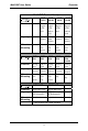
MultiVOIP User Guide Overview MultiVOIP Product Family MVP2410 MVP 24-48 MVP 3010 MVP 30-60 Function T1 digital VOIP unit T1 digital VOIP add-on card E1 digital VOIP unit E1 digital VOIP add-on card Capacity 24 24 channels added channels Chassis/ Mounting 19” 1U rack mount MVP 810 Description Model Description Model 30 channels 30 added channels circuit card only 19” 1U rack mount circuit card only MVP 428 MVP 410 MVP 210 MVP130/ analog voip add-on card analog voip analog voip
Overview MultiVOIP User Guide How to Use This Manual. In short, use the index and the examples. When our readers crack open this large manual, they generally need one of two things: information on a very specific software setting or technical parameter (about telephony or IP) or they need help when setting up phonebooks for their voip systems. The index gives quick access to voip settings and parameters. It’s detailed. Use it.
MultiVOIP User Guide Overview Introduction to TI MultiVOIPs (MVP2410 & MVP24-48) We proudly present MultiTech’s T1 Digital Multi-VOIP products. The MVP2410 is a rack-mount model; and the MVP24-48 is an add-on expansion card that doubles the capacity of the MVP2410 without adding another chassis. These voice-over-IP products have fax capabilities.
Overview MultiVOIP User Guide H.323, SIP & SPP. Being H.323 compatible, the MVP2410 can place calls to telephone equipment at remote IP network locations that also contain H.323 compatible voice-over-IP gateways. It will interface with H.323 software and H.323 gatekeeper units. H.323 specifications also bring to voip telephony many special features common to conventional telephony. H.
MultiVOIP User Guide Overview software residing in separate hardware). Gatekeepers are optional but useful within voip systems. The gatekeeper acts as the ‘clearinghouse’ for all calls within its zone. MultiTech’s stand-alone gatekeeper software performs all of the standard gatekeepers functions (address translation, admission control, and bandwidth control) and also supports many valuable optional functions (call control signaling, call authorization, bandwidth management, and call management).
Overview MultiVOIP User Guide While the web GUI’s appearance differs slightly, its content and organization are essentially the same as that of the Windows GUI (except for logging). The primary advantage of the web GUI is remote access for control and configuration. The controller PC and the MultiVOIP unit itself must both be connected to the same IP network and their IP addresses must be known. Once you’ve begun using the web browser GUI, you can go back to the MultiVOIP Windows GUI at any time.
MultiVOIP User Guide Overview Logging of System Events. MultiTech has built SysLog Server functionality into the software of the MultiVOIP units. SysLog is a de facto standard for logging events in network communication systems. The SysLog Server resides in the MultiVOIP unit itself. To implement this functionality, you will need a SysLog client program (sometimes referred to as a “daemon”). SysLog client programs, both paid and freeware, can be obtained from Kiwi Enterprises, among other firms. See www.
Overview MultiVOIP User Guide Supplementary Telephony Services. The H.450 standard (an addition to H.323) brings to voip telephony more of the premium features found in PSTN and PBX telephony. MultiVOIP units offer five of these H.450 features: Call Transfer, Call Hold, Call Waiting, Call Name Identification (not the same as Caller ID), and Call Forwarding.
MultiVOIP User Guide Overview MVP2410 Front Panel LED Definitions LED NAME DESCRIPTION Power Indicates presence of power. Boot After power up, the Boot LED will be on for about 10 seconds while the MVP2410 is booting. FDX Full-Duplex & Collision LED. This LED indicates whether the Ethernet connection is half-duplex or fullduplex (FDX) and, in half-duplex mode, indicates occurrence of data collisions. LED is on constantly for full-duplex mode; LED is off constantly for half-duplex mode.
Overview MultiVOIP User Guide Introduction to EI MultiVOIPs (MVP3010 & MVP30-60) We proudly present MultiTech’s E1 Digital Multi-VOIP products. The MVP3010 is a rack-mount model and the MVP30-60 is an add-on expansion card that doubles the capacity of the MVP3010 without adding another chassis. All of these voice-over-IP products have fax capabilities.
MultiVOIP User Guide Overview H. 323, SIP, & SPP. Being H.323 compatible, the MVP3010 can place calls to telephone equipment at remote IP network locations that also contain H.323 compatible voice-over-IP gateways. It will interface with H.323 software and H.323 gatekeeper units. H.323 specifications also bring to voip telephony many special features common to conventional telephony. H.
Overview MultiVOIP User Guide Gatekeeper. E1 voip systems can have gatekeeper functionality by adding, as an endpoint, a Multi-Tech standalone gatekeeper (special software residing in separate hardware). Gatekeepers are optional but useful within voip systems. The gatekeeper acts as the ‘clearinghouse’ for all calls within its zone.
MultiVOIP User Guide Overview While the web GUI’s appearance differs slightly, its content and organization are essentially the same as that of the Windows GUI (except for logging). The primary advantage of the web GUI is remote access for control and configuration. The controller PC and the MultiVOIP unit itself must both be connected to the same IP network and their IP addresses must be known. Once you’ve begun using the web browser GUI, you can go back to the MultiVOIP Windows GUI at any time.
Overview MultiVOIP User Guide Logging of System Events. MultiTech has built SysLog Server functionality into the software of the MultiVOIP units. SysLog is a de facto standard for logging events in network communication systems. The SysLog Server resides in the MultiVOIP unit itself. To implement this functionality, you will need a SysLog client program (sometimes referred to as a “daemon”). SysLog client programs, both paid and freeware, can be obtained from Kiwi Enterprises, among other firms. See www.
MultiVOIP User Guide Overview Supplementary Telephony Services. The H.450 standard (an addition to H.323) brings to voip telephony more of the premium features found in PSTN and PBX telephony. MultiVOIP units offer five of these H.450 features: Call Transfer, Call Hold, Call Waiting, Call Name Identification (not the same as Caller ID), and Call Forwarding.
Overview MultiVOIP User Guide E1 LED Descriptions MVP3010 Front Panel LED Definitions LED NAME DESCRIPTION Power Indicates presence of power. Boot After power up, the Boot LED will be on for about 10 seconds while the MVP3010 is booting. FDX Full-Duplex & Collision LED. This LED indicates whether the Ethernet connection is half-duplex or fullduplex (FDX) and, in half-duplex mode, indicates occurrence of data collisions.
MultiVOIP User Guide Overview Introduction to Analog MultiVOIPs (MVP-130/130FXS, MVP-210/410/810 & MVP428) VOIP: The Free Ride. We proudly present Multi-Tech's MVP130/130FXS and MVP-210/410/810 generation of MultiVOIP Voiceover-IP Gateways. All of these models allow voice/fax communication to be transmitted at no additional expense over your existing IP network, which has ordinarily been data only.
Overview MultiVOIP User Guide Figure 1-8: MultiVOIP MVP-130/130FXS Chassis Capacity. MultiVOIP model MVP810 is an eight-channel unit, the model MVP410 is a four-channel, the model MVP210 is a two-channel units, the MV130 is a single-channel unit and the MVP130FXS is a single-channel unit that supports the FXS telephony interface only. All of these MultiVOIP units have a 10/100Mbps Ethernet interface and a command port for configuration.
MultiVOIP User Guide Overview H. 323, SIP, & SPP. Being H.323 compatible, the analog MultiVOIP unit can place calls to telephone equipment at remote IP network locations that also contain H.323 compatible voice-over-IP gateways. It will interface with H.323 software and H.323 gatekeeper units. H.323 specifications also bring to voip telephony many special features common to conventional telephony. H.
Overview MultiVOIP User Guide Management. Configuration and system management can be done locally with the MultiVOIP configuration software. After an IP address has been assigned locally, other configuration can be done remotely using the MultiVOIP web browser GUI. Remote system management can be done with the MultiVoipManager SNMP software or via the MultiVOIP web browser GUI. All of these control software packages are included on the Product CD.
MultiVOIP User Guide Overview Once you’ve begun using the web browser GUI, you can go back to the MultiVOIP Windows GUI at any time. However, you must log out of the web browser GUI before using the MultiVOIP Windows GUI. Logging of System Events. MultiTech has built SysLog Server functionality into the software of the MultiVOIP units. SysLog is a de facto standard for logging events in network communication systems. The SysLog Server resides in the MultiVOIP unit itself.
Overview MultiVOIP User Guide Supplementary Telephony Services. The H.450 standard (an addition to H.323) brings to voip telephony more of the premium features found in PSTN and PBX telephony. MultiVOIP units offer five of these H.450 features: Call Transfer, Call Hold, Call Waiting, Call Name Identification (not the same as Caller ID), and Call Forwarding.
MultiVOIP User Guide Overview Similarly, the MVP210 has the general-operation indicator LEDs and two sets of channel-operation LEDs, one for each channel. Figure 1-10. MVP210 LEDs Finally, the MVP130 has the general-operation indicator LEDs and a set of channel-operation LEDs for its single voip channel. Figure 1-11.
Overview MultiVOIP User Guide Analog MultiVOIP LED Descriptions MVP-210/410/810 Front Panel LED Definitions LED NAME DESCRIPTION General Operation LEDs (one set on each MultiVOIP model) Power Indicates presence of power. Boot After power up, the Boot LED will be on briefly while the MultiVOIP is booting. It lights whenever the MultiVOIP is booting or downloading a setup configuration data set. FDX.
MultiVOIP User Guide Overview MVP-130/130FXS Front Panel LED Definitions LED NAME DESCRIPTION General Operation LEDs Power Indicates presence of power. Boot After power up, the Boot LED will be on briefly while the MultiVOIP is booting. It lights whenever the MultiVOIP is booting or downloading a setup configuration data set. FDX. LED indicates whether Ethernet connection is half-duplex or full-duplex (FDX) and, in half-duplex mode, indicates occurrence of data collisions.
Overview MultiVOIP User Guide Introduction to ISDN-BRI MultiVOIPs (MVP410ST & MVP810ST) VOIP: The Free Ride. We proudly present Multi-Tech's MVP410ST/810ST generation of MultiVOIP Voice-over-IP Gateways. All of these models allow voice/fax communication to be transmitted at no additional expense over your existing IP network, which has ordinarily been data only.
MultiVOIP User Guide Overview H. 323, SIP, & SPP. Being H.323 compatible, the BRI MultiVOIP unit can place calls to telephone equipment at remote IP network locations that also contain H.323 compatible voice-over-IP gateways. It will interface with H.323 software and H.323 gatekeeper units. H.323 specifications also bring to voip telephony many special features common to conventional telephony. H.
Overview MultiVOIP User Guide Management. Configuration and system management can be done locally with the MultiVOIP configuration software. After an IP address has been assigned locally, other configuration can be done remotely using the MultiVOIP web browser GUI. Remote system management can be done with the MultiVOIP web browser GUI. These control software packages are included on the Product CD.
MultiVOIP User Guide Overview Once you’ve begun using the web browser GUI, you can go back to the MultiVOIP Windows GUI at any time. However, you must log out of the web browser GUI before using the MultiVOIP Windows GUI. Logging of System Events. MultiTech has built SysLog Server functionality into the software of the MultiVOIP units. SysLog is a de facto standard for logging events in network communication systems. The SysLog Server resides in the MultiVOIP unit itself.
Overview MultiVOIP User Guide Supplementary Telephony Services. The H.450 standard (an addition to H.323) brings to voip telephony more of the premium features found in PSTN and PBX telephony. MultiVOIP units offer five of these H.450 features: Call Transfer, Call Hold, Call Waiting, Call Name Identification (not the same as Caller ID), and Call Forwarding.
MultiVOIP User Guide Overview ISDN-BRI MultiVOIP LED Descriptions MVP-410ST/810ST Front Panel LED Definitions LED NAME DESCRIPTION General Operation LEDs (one set on each MultiVOIP model) Power Indicates presence of power. Boot After power up, the Boot LED will be on briefly while the MultiVOIP is booting. It lights whenever the MultiVOIP is booting or downloading a setup configuration data set. FDX.
Overview MultiVOIP User Guide Computer Requirements The computer on which the MultiVOIP’s configuration program is installed must meet these requirements: • must be IBM-compatible PC with MS Windows operating system; • must have an available COM port for connection to the MultiVOIP. However, this PC does not need to be connected to the MultiVOIP permanently. It only needs to be connected when local configuration and monitoring are done.
MultiVOIP User Guide Overview Specifications Specs for Digital T1 MultiVOIP Units Digital T1 MultiVOIP Specifications Parameter ……/Model Operating Voltage/Current Mains Frequencies Power Consumption Mechanical Dimensions Weight 100-240 VAC 1.2 - 0.6 A 50/60 Hz MVP-2410 w/ MVP24-48 Expansion Card 100-240 VAC 1.2 - 0.6 A 50/60 Hz 17 watts 27 watts 1.75”H x 17.4”W x 8.75”D 1.75”H x 17.4”W x 8.75”D 4.5cm H x 44.2 cm W x 22.2 cm D 7.1 lbs. (3.2 kg) 4.5cm H x 44.2 cm W x 22.2 cm D 7.5 lbs. (3.
Overview MultiVOIP User Guide Specs for Digital E1 MultiVOIP Units Digital E1 MultiVOIP Specifications Parameter ……/Model MVP-3010 Operating Voltage/Current Mains Frequencies Power Consumption Mechanical Dimensions 100-240 VAC 1.2 - 0.6 A 50/60 Hz MVP-3010 w/ MVP30-60 Expansion Card 100-240 VAC 1.2 - 0.6 A 50/60 Hz 17 watts 27 watts 1.75”H x 17.4”W x 8.75”D 1.75”H x 17.4”W x 8.75”D 4.5cm H x 44.2 cm W x 22.2 cm D 7.1 lbs. (3.2 kg) 4.5cm H x 44.2 cm W x 22.2 cm D 7.5 lbs. (3.
MultiVOIP User Guide Overview Specs for Analog/BRI MultiVOIP Units Parameter /Model Operating Voltage/ Current Mains Frequencies Power Consumption Mechanical Dimensions Weight Parameter ……/Model Operating Voltage/ Current Mains Frequencies Power Consumption Mechanical Dimensions Weight MVP210 MVP410 External transformer: 3A @5V 50/60 Hz 100-240 VAC 1.2 - 0.6 A MVP810 or MVP410 + 428 100-240 VAC 1.2 - 0.6 A 50/60 Hz 50/60 Hz 19 watts 29 watts 46 watts 6.2” W x 9” D x 1.4” H 1.75” H x 17.
Overview MultiVOIP User Guide Installation at a Glance The basic steps of installing your MultiVOIP network involve unpacking the units, connecting the cables, and configuring the units using management software (MultiVOIP Configuration software) and confirming connectivity with another voip site. This process results in a fully functional Voice-Over-IP network. Related Documentation The MultiVOIP User Guide (the document you are now reading) comes in electronic form and is included on your system CD.
Chapter 2: Quick Start Instructions 45
Quick Start Instructions MultiVOIP User Guide Introduction This chapter gets the MultiVOIP up and running quickly. The details we’ve skipped to make this brief can be found elsewhere in the manual (see Table of Contents and Index). MultiVOIP Startup Tasks Task Summary z Collecting Phone/IP Details (vital!) The MultiVOIP must be configured to interface with your particular phone system and IP network. To do so, certain details must be known about those phone and IP systems.
MultiVOIP User Guide Quick Start Instructions Phone/IP Details *Absolutely Needed* Before Starting the Installation Gather IP Information 9 Ask your computer network administrator. # Info needed to operate: all MultiVOIP models.
Quick Start Instructions MultiVOIP User Guide Phone/IP Details *Absolutely Needed* (cont’d) Gather Telephone Information (E1) 9 E1 Phone Parameters Info needed to operate: MVP3010 Ask phone company or PBX maintainer.
MultiVOIP User Guide Quick Start Instructions Gather Telephone Information (ISDN BRI) 9 ISDN-BRI Phone Parameters Ask phone company or telecom manager. # Needed for: MVP810ST MVP410ST ISDN-BRI Telephony Interface Parameters: Record them for this VOIP Site • In which country is this voip installed? • Which operator (switch type) is used? • What type of line coding use required, A-law or u-law? • Determine which BRI ports will be network side and which BRI ports will be terminal side.
Quick Start Instructions MultiVOIP User Guide Phone/IP Details Often Needed/Wanted Obtain Email Address for VOIP (for email call log reporting) required if log reports of VOIP call traffic are to be sent by email Optional SMTP Parameters Preparation Task: To: I.T. Department Ask Mail Server administrator to set up email account (with password) for the MultiVOIP unit itself. Be sure to give a unique identifier to each individual MultiVOIP unit. re: email account for VOIP voip-unit2@biggytech.
MultiVOIP User Guide Quick Start Instructions Placement Mount your MultiVOIP in a safe and convenient location where cables for your network and phone system are accessible. Rack-mounting instructions are in Chapter 3: Mechanical Installation & Cabling.
Quick Start Instructions MultiVOIP User Guide Quick Hookups Hookup for MVP2410 & MVP3010 T1/E1 MultiVOIP Hookup (MVP-2410/3010) T1/E1/PRI cabling to your PBX, and/or to the PSTN. RJ-45 connector. Cabling to your IP network. RJ-45 connector. Digital Voice Command Trunk Cabling to POTS line (RJ-11 connector) for remote configuration via the built-in modem. Modem Grounding Screw Cabling to computer running MultiVOIP software. RJ-45 to serial connector (DB9).
MultiVOIP User Guide Quick Start Instructions Hookup for MVP410 & MVP810 Analog MultiVOIP Hookup MVP-410/810 MVP810 has 8 connector pairs. MVP410 has 4 connector pairs. Only 1 connector of any pair is used at a time. E&M FXS/FXO E&M FXS/FXO E&M FXS/FXO E&M FXS/FXO Cabling to computer running MultiVOIP software. Connector at MultiVOIP: DB-25. Connector at computer: DB-9.
Quick Start Instructions MultiVOIP User Guide Hookup for MVP410ST & MVP810ST ISDN MultiVOIP Hookup MVP-410ST/810ST Cabling to computer running MultiVOIP software. MVP810ST has 4 ISDN connectors. Connector at MultiVOIP: DB-25. MVP410ST has 2 ISDN connectors. Connector at computer: DB-9. ISDN1 ISDN2 ISDN3 ISDN4 Power Cable Receptacle Grounding Screw: Connect to Earth Ground Command On/Off Switch Cabling to phone equipment.
MultiVOIP User Guide Quick Start Instructions Hookup for MVP210 CH1 CH2 E&M FXS/FXO E&M FXS/FXO ETHERNET RS232 10/100 COMMAND POWER 10BASET COMMAND PORT POWER Voice/Fax Channel 1 - 2 Connections E&M FXO/FXS GND Power Connection FXS E&M FXO Command Port Connection PSTN Ethernet Connection 55
Quick Start Instructions MultiVOIP User Guide Hookup for MVP130 Power Ethernet Command FXS/FXO Power Connection Command Port Connection Hub Network Connection 56 FXS FXO PBX Telephony Connection PSTN
MultiVOIP User Guide Quick Start Instructions Hookup for MVP130FXS Pow er Eth erne t Co mmand VOICE FX S Power Connection Command Port Connection Hub Network Connection 57 Telephony Connection
Quick Start Instructions MultiVOIP User Guide Load MultiVOIP Control Software onto PC For more details, see Chapter 4: Software Installation. 1. MultiVOIP must be properly cabled. Power must be turned on. 2. Insert MultiVOIP CD into drive. Allow 10-20 seconds for Autorun to start. If Autorun fails, go to My Computer | CD ROM drive | Open. Click Autorun icon. 3. At first dialog box, click Install Software. 4. At ‘welcome’ screen, click Next. 5. Follow on-screen instructions.
MultiVOIP User Guide Quick Start Instructions Phone/IP Starter Configuration Full details here: MVP2410 MVP3010 MVP130 MVP130FXS MVP210 MVP410 MVP810 Chapter 5: Technical Configuration for Digital T1/E1 MultiVOIPs in User Guide. Chapter 6: Technical Configuration for Analog/BRI MultiVOIPs in User Guide 1. Open MultiVOIP program: Start | MultiVOIP xxx | Configuration. 2. Go to Configuration | IP. Enter the IP parameters for your voip site. 3.
Quick Start Instructions MultiVOIP User Guide Once you’ve begun using the web browser GUI, you can go back to the MultiVOIP Windows GUI at any time. However, you must log out of the web browser GUI before using the MultiVOIP Windows GUI. 5. Go to Configuration | Voice/Fax. Select Coder | “Automatic.” At the right-hand side of the dialog box, click Default. If you know any specific parameter values that will apply to your system, enter them. Click Copy Channel. Select Copy to All. Click Copy.
MultiVOIP User Guide Quick Start Instructions groupings of telephony parameters than do the Country/Region values.) Click OK to exit from the Regional Parameters dialog box. 9. Do you want the phone-call logs produced by the MultiVOIP to be sent out by email (to your Voip Administrator or someone else)? If NO, skip to step 11. If YES, continue with step 10. 10. Go to Configuration | SMTP. SMTP lets you send phone-call log records to the Voip Administrator by email. Select Enable SMTP.
Quick Start Instructions MultiVOIP User Guide Phone/IP Starter Configuration (continued) 12. Enable premium (H.450) telephony features. Go to Supplementary Services. Select any features to be used. For Call Hold, Call Transfer, & Call Waiting, specify the key sequence that the phone user will press to invoke the feature. For Call Name Identification, specify the allowed name types to be used and a callerid descriptor.
MultiVOIP User Guide Quick Start Instructions Phonebook Starter Configuration (with remote voip) If the topic of voip phone books is new to you, it may be helpful to read the PhoneBook Tips section (page 71) before starting this procedure. To do this part of the quick setup, you need to know of another voip that you can call to conduct a test. It should be at a remote location, typically somewhere outside of your building. You must know the phone number and IP address for that site.
Quick Start Instructions MultiVOIP User Guide 4. Suppose you want to call a phone number outside of your building using a phone station that is an extension from your PBX system (if present). What digits must you dial? Often a “9” or “8” must be dialed to “get an outside line” through the PBX (i.e., to connect to the PSTN). Generally, “1 “or “11” or “0” must be dialed as a prefix for calls outside of the calling code area (long-distance calls, national calls, or international calls).
MultiVOIP User Guide Quick Start Instructions 5. In the “Destination Pattern” field of the Add/Edit Outbound Phonebook screen, enter the digits from step 4 followed by the digits from step 3. North America, Long-Distance Example Seattle-Chicago system. Answer: enter 81312 as Destination Pattern in Outbound Phone book of Seattle voip. Euro, National Call Example London/Birming. system. Leading zero of Birmingham area code is dropped when combined with national-dialing access code.
Quick Start Instructions MultiVOIP User Guide 6. Tally up the number of digits that must be dialed to reach the remote voip site (including prefix digits of all types). Enter this number in the “Total Digits” field. North America, Long-Distance Example Euro, National Call Example Seattle-Chicago system. London/Birming. system. To complete Seattle-toChicago call, 81312 must be followed by the 7-digit local phone number in Chicago.
MultiVOIP User Guide Quick Start Instructions field in the Outbound Phonebook. This precludes the problem of having to make two inbound phonebook entries at remote voips, one to account for situations where “8” is used as the PBX access digit, and another for when “9” is used. 8. Select the voip protocol that you will use (H.323, SIP, or SPP). 9. Click OK to exit from the Add/Edit Outbound Phonebook screen. Inbound Phonebook 1. Open the MultiVOIP program. (Start | MultiVOIP xxx | Configuration 2.
Quick Start Instructions MultiVOIP User Guide 4. In the “Add Prefix” field, enter any digits that must be dialed from your local voip to gain access to the PSTN. North America, Long-Distance Example Euro, National Call Example Seattle-Chicago system. London/Birming. system. On Seattle PBX, “8” is used to get an outside line. On London PBX, “9” is used to get an outside line. Answer: 8 is the prefix to be added by local (Seattle) voip. Answer: 9 is the prefix to be added by local (London) voip.
MultiVOIP User Guide Quick Start Instructions 6. In the “Description” field, it is useful to describe the ultimate destination of the calls. For example, in a New York City voip system, “incoming calls to Manhattan office,” might describe a phonebook entry, as might the descriptor “incoming calls to NYC local calling area.” The description should make the routing of calls easy to understand. (40 characters max.) North America, Long-Distance Example Euro, National Call Example Seattle-Chicago system.
Quick Start Instructions MultiVOIP User Guide Phonebook Tips Preparing the phonebook for your voip system is a complex task that, at first, seems quite daunting. These tips may make the task easier. 1. Use Dialing Patterns, Not Complete Phone Numbers. You will not generally enter complete phone numbers in the voip phonebook. Instead, you’ll enter “destination patterns” that involve area codes and other digits.
MultiVOIP User Guide Quick Start Instructions (b) access codes. There are digits (PSTN access codes) that must be dialed to gain access to an operator, to access the publicly switched ‘long-distance’ calling system(North America), to access the publicly switched ‘national’ calling system (Europe and elsewhere), or to access the publicly switched ‘international’ calling system (worldwide). There are digits (PBX access codes) that must be dialed by phones connected to PBX systems or key systems.
Quick Start Instructions MultiVOIP User Guide 4. Using a Comma. Commas are used in telephone dialing strings to indicate a pause to allow a dial tone to appear (common on PBX and key systems). Commas may be used only in the “Add Prefix” field of the Inbound Phonebook. , Detail = 1-second pause In many PBX systems (not needed in all) 5. Ease of Use. The phonebook setup determines how easy the voip system is to use.
MultiVOIP User Guide Quick Start Instructions Phonebook Example One Common Situation Boise Office PBX System. Main Number: 333-2700 Area: 208 PSTN 90 extensions 204.16.49.73 24-Channel Digital VoIP (MVP2410) Voip Example. This company has offices in three different cities. The PBX units all operate alike. Notably, they all give access to outside lines using “9.” They all are ‘smart’ enough to identify voip calls without using a special access digit (“8” is used in some systems).
Quick Start Instructions MultiVOIP User Guide Voip Sites with Phonebooks Boise Office PBX System. Main Number: 333-2700 Boise Voip Boise Voip Inbound Phonebook Area: 208 Prefix to Remove 91208 PSTN Prefix to Add Destin. Pattern Incoming calls 91505 to PSTN, Boise Area i ncoming calls 2 to extensions of company’s PBX system in Boise 91520 9, 7 90 extensions Outbound Phonebook Description Incoming Calls 7 204.16.49.
MultiVOIP User Guide Quick Start Instructions Sample Phonebooks Enlarged Boise Voip Boise Voip Inbound Phonebook Outbound Phonebook Prefix to Remove 91208 7 Prefix to Add 9, 7 Description Incoming Calls Destin. Pattern Incoming calls 91505 to PSTN, Boise Area i ncoming calls 2 to extensions of company’s PBX system in Boise 91520 6 Total Digits Prefix to Remove Prefix to Add IP Addr Description Outgoing Calls 12 none none 204. 16.49. 74 3 none none 204. 16.49.
Quick Start Instructions MultiVOIP User Guide Phonebook Worksheet Voip Location/ID:____________________________ Inbound Phonebook Prefix to Remove Prefix to Add Outbound Phonebook Description Incoming Calls Destin. Pattern Total Digits Prefix to Remove Prefix to Add IP Addr Description Outgoing Calls Other Details: Voip Location/ID:____________________________ Inbound Phonebook Prefix to Remove Prefix to Add Description Incoming Calls Outbound Phonebook Destin.
MultiVOIP User Guide Quick Start Instructions Enlarged Phonebook Worksheet 77
Quick Start Instructions MultiVOIP User Guide Connectivity Test The procedures “Phone/IP Starter Configuration” and “Phonebook Starter Configuration” must be completed before you can do this procedure. 1.
MultiVOIP User Guide Quick Start Instructions 5. Open the HyperTerminal program. 6. Use HyperTerminal to receive and record console messages from the MultiVOIP unit. To do so, set up HyperTerminal as follows (setup shown is for Windows NT4; details will differ slightly in other MS operating systems): y In the upper toolbar of the HyperTerminal screen, click on the Properties button. y In the “Connect To” tab of the Connection Properties dialog box, click on the Configure button.
Quick Start Instructions MultiVOIP User Guide 8. Read console messages recorded on HyperTerminal. Console Messages from Originating VOIP. The voip unit that originates the call will send back messages like that shown below.
MultiVOIP User Guide Quick Start Instructions Console Messages from Terminating VOIP. The voip unit connected to the phone where the call is answered will send back messages like that shown below.
Quick Start Instructions MultiVOIP User Guide Troubleshooting If you cannot establish connectivity between two voips in the system, follow the steps below to determine the problem. 1. Ping both MultiVOIP units to confirm connectivity to the network. 2. Verify the telephone connections. A. For MVP2410 or MVP3010. y Check cabling. Are connections well seated? To correct receptacle? y Is the ONL LED on? (If on, ONL indicates that the MultiVOIP is online on the network.
MultiVOIP User Guide Quick Start Instructions 3. Verify phonebook configuration. 4. Observe console messages while placing a call. Look for error messages indicating phonebook problems, network problems, voicecoder mismatches, etc.
Mechanical Installation & Cabling MultiVOIP User Guide Chapter 3: Mechanical Installation and Cabling 84
MultiVOIP User Guide Mechanical Installation & Cabling Introduction The MultiVOIP models MVP130, MVP130FXS and MVP210 are tabletop units and can be handled easily by one person. However, the MVP410, MVP810, MVP2410, and MVP3010 are somewhat heavier units. When these units are to be installed into a rack, two able-bodied persons should participate. Please read the safety notices before beginning installation.
Mechanical Installation & Cabling MultiVOIP User Guide Unpacking Your MultiVOIP When unpacking your MultiVOIP, check to see that all of the items shown are included in the box. For the various MultiVOIP models, the contents of the box will be different. Study the particular illustration below that is appropriate to the model you have purchased. If any box contents are missing, contact MultiTech Tech Support at 1-800-972-2439.
MultiVOIP User Guide Mechanical Installation & Cabling Unpacking the MVP-410/810 Quick Start Guide Voice/Fax over IP Networks Voice/Fax 5 XMT Power Ethernet Boot RCV XMT COL RCV XSG Voice/Fax 6 RSG XMT RSG XMT Voice/Fax 1 LNK XMT RCV XSG RCV XSG Voice/Fax 7 RSG XMT RSG XMT Voice/Fax 2 RCV XSG RCV XS G Voice/Fax 8 RSG XMT RSG XMT RCV XS G RCV XSG RSG Voice/Fax 4 Voice/Fax 3 RCV XSG RSG Figure 3-2: Unpacking the MVP-410/810 87
Mechanical Installation & Cabling MultiVOIP User Guide Unpacking the MVP210 200 Voice/Fax over IP Networks Quick Start Guide Figure 3-3: Unpacking the MVP210 88
MultiVOIP User Guide Mechanical Installation & Cabling Unpacking the MVP-130/130FXS Figure 3-4: Unpacking the MVP-130/130FXS 89
Mechanical Installation & Cabling MultiVOIP User Guide Rack Mounting Instructions for MVP-2410/3010 & MVP-410/810 The MultiVOIPs can be mounted in an industry-standard EIA 19-inch rack enclosure, as shown in Figure 3-5.
MultiVOIP User Guide Mechanical Installation & Cabling Safety Recommendations for Rack Installations Ensure proper installation of the unit in a closed or multi-unit enclosure by following the recommended installation as defined by the enclosure manufacturer. Do not place the unit directly on top of other equipment or place other equipment directly on top of the unit.
Mechanical Installation & Cabling MultiVOIP User Guide 19-Inch Rack Enclosure Mounting Procedure Attaching the MultiVOIP to a rack-rail of an EIA 19-inch rack enclosure will certainly require two persons. Essentially, the technicians must attach the brackets to the MultiVOIP chassis with the screws provided, as shown in Figure 3-6, and then secure unit to rack rails by the brackets, as shown in Figure 3-7. Because equipment racks vary, screws for rack-rail mounting are not provided.
MultiVOIP User Guide Mechanical Installation & Cabling Cabling Cabling Procedure for MVP2410/3010 Cabling your MultiVOIP entails making the proper connections for power, command port, phone system (T1/E1 line connected to PBX or telco office), and Ethernet network. Figure 3-8 shows the back panel connectors and the associated cable connections. The following procedure details the steps necessary for cabling your MultiVOIP. 1.
Mechanical Installation & Cabling MultiVOIP User Guide 4. If you intend to configure the MultiVOIP remotely using the MultiVOIP Windows GUI, connect an RJ-11 phone cable between the Command Modem connector (at the rear of the MultiVOIP) and a receptacle served by a telco POTS line. See Figure 3-9. The Command Modem is built into the MultiVOIP unit. To configure the MultiVOIP remotely using its Windows GUI, you must call into the MultiVOIP’s Command Modem.
MultiVOIP User Guide Mechanical Installation & Cabling Cabling Procedure for MVP-410/810 Cabling involves connecting the MultiVOIP to your LAN and telephone equipment. 1. For DID channels only. If all channels of your MultiVOIP will be using either FXS, FXO, or E&M telephony interfaces, skip to step 2. For any channel on which you are using the DID interface type, you must change the jumper on the MultiVOIP circuit card. a. Disconnect power.
Mechanical Installation & Cabling MultiVOIP User Guide d. Identify the channels on which the DID interface will be used. Jumper Configurations (enlarged) Upper Circuit Card MVP810 only Ch 5 U7 Ch 6 U9 Ch 7 U8 For DID Interface type Ch 8 U10 Jumpers 5-8 For non-DID Interface type } Main Circuit Card MVP-410/810 Ch 1 Ch 2 Ch 3 Ch 4 } Jumpers 1-4 Generality: For channels using the DID interface, the jumper must not straddle across the cross-hatched area between the jumper posts.
MultiVOIP User Guide Mechanical Installation & Cabling 2. Connect the power cord supplied with your MultiVOIP to a live AC outlet and to the power connector on the back of the MultiVOIP as shown at top right in Figure 3-12.
Mechanical Installation & Cabling MultiVOIP User Guide Connect the other end to the trunk line. Verify that the E&M Type in the E&M Options group of the Interface dialog box is the same as the E&M trunk type supported by the telephone switch. See Appendix B for an E&M cabling pinout. For a DID connection. (DID Example: DID fax system or DID voice phone lines.) Connect one end of an RJ-11 phone cord to the Channel 1 FXS/FXO connector on the back of the MultiVOIP. Connect the other end to the DID jack.
MultiVOIP User Guide Mechanical Installation & Cabling 8. Ensure that the unit is properly connected to earth ground by verifying that it is reliably grounded when mounted within a rack. This can be accomplished by connecting a grounding wire between the chassis grounding screw (see Figure 3-13) and a metallic object that will provide an electrical ground. 9. Turn on power to the MultiVOIP by placing the ON/OFF switch on the back panel to the ON position.
Mechanical Installation & Cabling MultiVOIP User Guide Cabling Procedure for MVP-410ST/810ST Cabling involves connecting the MultiVOIP to your LAN and telephone equipment. 1. Connect the power cord supplied with your MultiVOIP to a live AC outlet and to the power connector on the back of the MultiVOIP as shown at top right in Figure 3-14.
MultiVOIP User Guide Mechanical Installation & Cabling 4. Terminal Mode. When a voip ISDN connector is to be connected to a PBX extension line or to a telco line, select “Terminal” as the “Layer 1 Interface” in the ISDN Parameters screen. When making cable connections, an NT1 device will be needed between the MultiVOIP and the PSTN or between the MultiVOIP and any PBX with a “U” interface. (For more information, see Appendix B: Cable Pinouts in this manual.
Mechanical Installation & Cabling MultiVOIP User Guide Network Mode. When a voip ISDN connector is to be connected to an ISDN phone station or to an ISDN terminal adapter (TA), select “Network” as the “Layer 1 Interface” in the ISDN Parameters screen of the MultiVOIP software. Connect cables between voip ISDN connectors and phone or TA. NOTE. Any ISDN phone stations connected to the MVP- 410ST/810ST must provide their own operating power.
MultiVOIP User Guide Mechanical Installation & Cabling 5. Repeat the above step to connect the remaining ISDN telephone equipment to each ISDN connector on your MultiVOIP. Be aware that you can assign each ISDN line separately and independently to either Network mode or Terminal mode. That is, all ISDN lines do not have to be assigned in to the same operating mode.
Mechanical Installation & Cabling MultiVOIP User Guide Cabling Procedure for MVP210 Cabling involves connecting the MultiVOIP to your LAN and telephone equipment. 1. For DID channels only. If both channels of your MVP210 MultiVOIP will be using either FXS, FXO, or E&M telephony interfaces, skip to step 2. For any channel on which you are using the DID interface type, you must change the jumper on the MultiVOIP circuit card. a. Disconnect power.
MultiVOIP User Guide Mechanical Installation & Cabling d. Identify the channels on which the DID interface will be used.
Mechanical Installation & Cabling MultiVOIP User Guide Figure 3-17: Cabling for MVP210 3. Connect the MultiVOIP to a PC by using a RJ-45 (male) to DB-9 (female) cable. Plug the RJ-45 end of the cable into the Command port of the MultiVOIP and the other end into the PC serial port. See Figure 3-17. 4. Connect a network cable to the ETHERNET 10/100 connector on the back of the MultiVOIP. Connect the other end of the cable to your network. 5. For an FXS or FXO connection.
MultiVOIP User Guide Mechanical Installation & Cabling Connect one end of an RJ-11 phone cord to the Channel 1 FXS/FXO connector on the back of the MultiVOIP. Connect the other end to the DID jack. NOTE: DID lines are polarity sensitive. If, during testing, the DID line rings busy consistently, you will need to reverse the polarity of one end of the connector (swap the connections of the wires to the two middle pins of one RJ-11 connector). 6.
Mechanical Installation & Cabling MultiVOIP User Guide Cabling Procedure for MVP-130/130FXS Power Ethernet Command FXS/FXO Power Connection Command Port Connection FXS FXO PBX Telephony Connection PSTN Hub Network Connection Figure 3-18: Cabling for MVP-130/130FXS Cabling involves connecting the MultiVOIP to your LAN and telephone equipment. 1.
MultiVOIP User Guide Mechanical Installation & Cabling the other end to the device or phone jack. You will define the interface in the Interface dialog box in the software when you configure the unit. The MVP130FXS supports only the FXS interface. Proceed to Chapter 4 to load the MultiVOIP software.
Software Installation MultiVOIP User Guide Chapter 4: Software Installation 110
MultiVOIP User Guide Software Installation Introduction Configuring software for your MultiVOIP entails three tasks: (1) loading the software onto the PC (this is “Software Installation and is discussed in this chapter), (2) setting values for telephony and IP parameters that will fit your system (this is “Technical Configuration” and it is discussed in Chapter 5 for T1/E1 MultiVOIP units and in Chapter 6 for analog MultiVOIP units), and (3) establishing “phonebooks” that contain the various dialing patte
Software Installation MultiVOIP User Guide 2. Insert the MultiVOIP CD into your CD-ROM drive. The CD should start automatically. It may take 10 to 20 seconds for the Multi-Tech CD installation window to display. If the Multi-Tech Installation CD window does not display automatically, click My Computer, then right click the CD ROM drive icon, click Open, and then click the Autorun icon. 3. When the Multi-Tech Installation CD dialog box appears, click the Install Software icon.
MultiVOIP User Guide Software Installation 4. A ‘welcome’ screen appears. Press Enter or click Next to continue.
Software Installation MultiVOIP User Guide 5. Follow the on-screen instructions to install your MultiVOIP software. The first screen asks you to choose the folder location of the files of the MultiVOIP software. Choose a location and click Next.
MultiVOIP User Guide Software Installation 6. At the next screen, you must select a program folder location for the MultiVOIP software program icon. Click Next. Transient progress screens will appear while files are being copied.
Software Installation MultiVOIP User Guide 7. On the next screen you can select the COM port that the command PC will use when communicating with the MultiVoip unit. After software installation, the COM port can be re-set in the MultiVOIP Software (from the sidebar menu, select Connection | Settings to access the COM Port Setup screen or use the keyboard shortcut Ctrl + G).
MultiVOIP User Guide Software Installation 8. A completion screen will appear. Click Finish. 9. When setup of the MultiVOIP software is complete, you will be prompted to run the MultiVOIP software to configure the VOIP. Software installation is complete at this point. You may proceed with Technical Configuration now or not, at your convenience. Technical Configuration instructions are in the next two chapters of this manual: Chapter 5 for T1/E1 MultiVOIP units and Chapter 6 for Analog MultiVOIP units.
Software Installation MultiVOIP User Guide Un-Installing the MultiVOIP Configuration Software 1. To un-install the MultiVOIP configuration software, go to Start | Programs and locate the entry for the MultiVOIP program. Select Uninstall.
MultiVOIP User Guide Software Installation 2. Two confirmation screens will appear. Click Yes and OK when you are certain you want to continue with the uninstallation process. 3. A special warning message similar to that shown below may appear concerning the MultiVOIP software’s “.bin” file. Click Yes.
Software Installation MultiVOIP User Guide 4. A completion screen will appear. Click Finish.
MultiVOIP User Guide Technical Configuration (T1/E1) Chapter 5: Technical Configuration for Digital T1/E1 MultiVOIPs (MVP2410, MVP3010) 121
Technical Configuration (T1/E1) MultiVOIP User Guide Configuring the Digital T1/E1 MultiVOIP There are two ways in which the MultiVOIP must be configured before operation: technical configuration and phonebook configuration. Technical Configuration. First, the MultiVOIP must be configured to operate with technical parameter settings that will match the equipment with which it interfaces. There are seven types of technical parameters that must be set.
MultiVOIP User Guide Technical Configuration (T1/E1) Remote configuration is done through a connection between the MultiVOIP’s Ethernet (network) port and a computer connected to the same network. The computer could be miles or continents away from the MultiVOIP itself. There are two ways of doing remote configuration and operation of the MultiVOIP unit: (1) using the MultiVoipManager SNMP program, or (2) using the MultiVOIP web browser interface program. MultiVoipManager.
Technical Configuration (T1/E1) MultiVOIP User Guide Local Configuration This manual primarily describes local configuration with the Windows GUI. After IP addresses have been set locally using the Windows GUI, however, most aspects of configuration (logging functions are an exception) can be handled through the web browser GUI, as well (see the Operation and Maintenance chapter of this manual).
MultiVOIP User Guide Technical Configuration (T1/E1) Write down the values for these IP parameters. You will need to enter these values in the “IP Parameters” screen in the Configuration section of the MultiVOIP software. You must have this IP information about every VOIP in the system.
Technical Configuration (T1/E1) MultiVOIP User Guide E1 Telephony Parameters (for MVP3010) The following parameters must be known about the PBX or telco central office equipment to which the E1 MultiVOIP will connect: 9 E1 Phone Parameters Ask phone company or PBX maintainer.
MultiVOIP User Guide Technical Configuration (T1/E1) SMTP Parameters (for email call log reporting) required if log reports of VOIP call traffic are to be sent by email Optional SMTP Parameters Preparation Task: To: I.T. Department Ask Mail Server administrator to set up email account (with password) for the MultiVOIP unit itself. Be sure to give a unique identifier to each individual MultiVOIP unit. . re: email account for VOIP voip-unit2@biggytech.
Technical Configuration (T1/E1) MultiVOIP User Guide Local Configuration Procedure (Summary) After the MultiVOIP configuration software has been installed in the ‘Command’ PC (which is connected to the MultiVOIP unit), several steps must be taken to configure the MultiVOIP to function in its specific setting. Although the summary below includes all of these steps, some are optional. 1. Check Power and Cabling. 2. Start MultiVOIP Configuration Program. 3. Confirm Connection. 4.
MultiVOIP User Guide Technical Configuration (T1/E1) Local Configuration Procedure (Detailed) You can begin the configuration process as a continuation of the MultiVOIP software installation. You can establish your configuration or modify it at any time by launching the MultiVOIP program from the Windows Start menu. 1. Check Power and Cabling.
Technical Configuration (T1/E1) MultiVOIP User Guide 3. Confirm Connection. If the MultiVOIP is set for an available COM port and is correctly cabled to the PC, the MultiVOIP main screen will appear. (If the main screen appears grayed out and seems inaccessible, go to step 4.
MultiVOIP User Guide Technical Configuration (T1/E1) In the lower left corner of the screen, the connection status of the MultiVOIP will be displayed. The messages in the lower left corner will change as detection occurs. The message “MultiVOIP Found” confirms that the MultiVOIP is in contact with the MultiVOIP configuration program. Skip to step 5.
Technical Configuration (T1/E1) MultiVOIP User Guide 4. Solving Common Connection Problems. A. Fixing a COM Port Problem. If the MultiVOIP main screen appears but is grayed out and seems inaccessible, the COM port that was specified for its communication with the PC is unavailable and must be changed. An error message will appear.
MultiVOIP User Guide Technical Configuration (T1/E1) 4B. Fixing a Cabling Problem. If the MultiVOIP cannot be located by the computer, two error messages will appear (saying “Multi-VOIP Not Found” and “Phone Database Not Read”). In this case, the MultiVOIP is simply disconnected from the network. For instructions on MultiVOIP cable connections, see the “Cabling” section of Chapter 3. 5. Configuration Parameter Groups: Getting Familiar, Learning About Access.
Technical Configuration (T1/E1) MultiVOIP User Guide 6. Set IP Parameters. This dialog box can be reached by pulldown menu, toolbar icon, keyboard shortcut, or sidebar.
MultiVOIP User Guide Technical Configuration (T1/E1) In each field, enter the values that fit your particular network.
Technical Configuration (T1/E1) MultiVOIP User Guide The IP Parameters fields are described in the table below. IP Parameter Definitions Field Name Values Description DiffServ Parameter fields DiffServ PHB (Per Hop Behavior) values pertain to a differential prioritizing system for IP packets as handled by DiffServ-compatible routers. There are 64 values, each with an elaborate technical description.
MultiVOIP User Guide Technical Configuration (T1/E1) The IP Datagram with Header, Its Type-of-Service field, & DiffServ bits => 0 VERS 4 HLEN 8 16 19 24 31 TYPE OF TOTAL LENGTH SERVICE FLAGS IDENTIFICATION FRAGMENT OFFSET TIME TO LIVE PROTOCOL HEADER CHECKSUM SOURCE IP ADDRESS DESTINATION IP ADDRESS IP OPTIONS (if any) PADDING … end of header DATA … The TOS field consists of eight bits, of which only the first six are used.
Technical Configuration (T1/E1) MultiVOIP User Guide IP Parameter Definitions (cont’d) Field Name Values Description IP Parameter fields Enable DHCP Y/N Dynamic Host disabled by default Configuration Protocol is a method for assigning IP address and other IP parameters to computers on the IP network in a single message with great flexibility. IP addresses can be static or temporary depending on the needs of the computer.
MultiVOIP User Guide Technical Configuration (T1/E1) 7. Enable Web Browser GUI (Optional). After an IP address for the MultiVOIP unit has been established, you can choose to do any further configuration of the unit (a) by using the MultiVOIP web browser GUI, or (b) by continuing to use the MultiVOIP Windows GUI. If you want to do configuration work using the web browser GUI, you must first enable it. To do so, follow the steps below. A.
Technical Configuration (T1/E1) MultiVOIP User Guide 8. Set Voice/FAX Parameters. This dialog box can be reached by pulldown menu, toolbar icon, keyboard shortcut, or sidebar.
MultiVOIP User Guide Technical Configuration (T1/E1) In each field, enter the values that fit your particular network.
Technical Configuration (T1/E1) MultiVOIP User Guide Note that Voice/FAX parameters are applied on a channel-by-channel basis. However, once you have established a set of Voice/FAX parameters for a particular channel, you can apply this entire set of Voice/FAX parameters to another channel by using the Copy Channel button and its dialog box. To copy a set of Voice/FAX parameters to all channels, select “Copy to All” and click Copy.
MultiVOIP User Guide Technical Configuration (T1/E1) The Voice/FAX Parameters fields are described in the tables below. Field Name Default Voice/Fax Parameter Definitions Values Description -When this button is clicked, all Voice/FAX parameters are set to their default values. Select Channel 1-24 (T1) 1-30 (E1) Channel to be configured is selected here. Copy Channel -- Copies the Voice/FAX attributes of one channel to another channel.
Technical Configuration (T1/E1) MultiVOIP User Guide Voice/Fax Parameter Definitions (cont’d) Field Name Values Description DTMF Parameters Duration 60 – 3000 (DTMF) ms DTMF In/Out of Band When DTMF: Out of Band is selected, this setting determines how long each DTMF digit ‘sounds’ or is held. Default = 100 ms. Out of Band, or Inband When DTMF Out of Band is selected (checked), the MultiVOIP detects DTMF tones at its input and regenerates them at its output.
MultiVOIP User Guide Technical Configuration (T1/E1) Voice/Fax Parameter Definitions (cont’d) Coder Parameters Coder Manual or Determines whether selection of Autocoder is manual or automatic. matic When Automatic is selected, the local and remote voice channels will negotiate the voice coder to be used by selecting the highest bandwidth coder supported by both sides without exceeding the Max Bandwidth setting. G.723, G.729, or G.711 are negotiated. Selected G.
Technical Configuration (T1/E1) MultiVOIP User Guide Voice/Fax Parameter Definitions (cont’d) Field Name Values Description Advanced Features Silence Y/N Determines whether silence compression is enabled (checked) for this voice channel. Compression With Silence Compression enabled, the MultiVOIP will not transmit voice packets when silence is detected, thereby reducing the amount of network bandwidth that is being used by the voice channel. Default = off.
MultiVOIP User Guide Technical Configuration (T1/E1) Voice/Fax Parameter Definitions (cont’d) Field Name Values Description AutoCall/Offhook Alert Parameters Auto Call / Offhook Alert AutoCall, Offhook Alert The AutoCall option enables the local MultiVOIP to call a remote MultiVOIP without the user having to dial a Phone Directory Database number.
Technical Configuration (T1/E1) MultiVOIP User Guide Voice/Fax Parameter Definitions (cont’d) Field Name Values Description AutoCall/Offhook Alert Parameters Offhook Alert Timer N/A Not supported in T1/E1 MultiVOIP units. Phone Number N/A Not supported in T1/E1 MultiVOIP units.
MultiVOIP User Guide Technical Configuration (T1/E1) Voice/Fax Parameter Definitions (cont’d) Field Name Values Description Dynamic Jitter Buffer Parameters Dynamic Jitter Buffer Dynamic Jitter defines a minimum and a maximum jitter value for voice communications. When receiving voice packets from a remote MultiVOIP, varying delays between packets may occur due to network traffic problems. This is called Jitter. To compensate, the MultiVOIP uses a Dynamic Jitter Buffer.
Technical Configuration (T1/E1) MultiVOIP User Guide Voice/Fax Parameter Definitions (cont’d) Field Name Values Description Dynamic Jitter Buffer Parameters Maximum Jitter Value 60 to 400 ms The default maximum dynamic jitter buffer of 300 milliseconds is the maximum delay tolerable over a high jitter network.
MultiVOIP User Guide Technical Configuration (T1/E1) Voice/Fax Parameter Definitions (cont’d) ) Field Name Values Description Auto Disconnect Parameters The Automatic Disconnection group has four options which can be used singly or in any combination. Jitter Value 1-65535 milliseconds The Jitter Value defines the average inter-arrival packet deviation (in milliseconds) before the call is automatically disconnected. The default is 150 milliseconds.
Technical Configuration (T1/E1) MultiVOIP User Guide 9. Set T1/E1/ISDN Parameters. This dialog box can be reached by pulldown menu, toolbar icon, keyboard shortcut, or sidebar.
MultiVOIP User Guide Technical Configuration (T1/E1) In each field, enter the values that fit your particular network.
Technical Configuration (T1/E1) MultiVOIP User Guide T1 Parameters. The parameters applicable to T1 and their values are shown in the figure below. These T1 Parameter fields are described in the tables that follow.
MultiVOIP User Guide Technical Configuration (T1/E1) T1 Parameter Definitions Field Name Values Description T1/E1/ISDN T1 North American standard. Long-Haul Mode Y/N In Long-Haul Mode, the MultiVOIP automatically recovers received signals as low as –36 dB. The maximum reachable length with 22 AWG cable is 2000 meters. When Long-Haul Mode is disabled, signals as low as –10 dB can be received. Default: disabled. CRC Check Y/N When enabled, allows generation and checking of CRC bits.
Technical Configuration (T1/E1) MultiVOIP User Guide T1 Parameter Definitions (cont’d) Field Name Values Description CAS Protocol E&M Immed Strt E&M Wink Start Channel Associated Signaling (CAS) is a method of incorporating telephony signaling info into a T1 voice/data stream. In CAS, the signaling bits (the A, B, C, and D bits) are multiplexed into the signal stream of each T1 channel. (By contrast, in Common Channel Signaling (CCS), one channel handles signaling for all other channels.
MultiVOIP User Guide Technical Configuration (T1/E1) T1 Parameter Definitions (cont’d) Field Name Values Description Detect Flash Hook Y/N This setting determines whether or not the MultiVOIP responds to hook-flash signals. Detection Time 100 – 1500 milliseconds Minimum hook-flash time that will be interpreted as a valid flash by the MultiVOIP.
Technical Configuration (T1/E1) MultiVOIP User Guide T1 Parameter Definitions (cont’d) ISDN Parameters Field Name Values Description Enable ISDN-PRI Y/N If digital connection is ISDNPRI type, this box should be checked. When ISDN is enabled, the “CAS Protocols” field is grayed out (ISDN has its own signaling method). Terminal/ Network either “Terminal” or “Network” When “Terminal” is selected, it indicates that the MultiVOIP should emulate the subscriber (terminal) side of the digital connection.
MultiVOIP User Guide Technical Configuration (T1/E1) T1 Parameter Definitions (cont’d) Field Name Values Description Line Build Out 0 dB, -7.5 dB, -15 dB, -22.5 dB To reduce the crosstalk on received signals, a transmit attenuator can be placed in the data path. Transmit attenuation is selectable. Default: O dB Pulse Shape Level 0 to 40 Meters 40 to 81 m 81 to 122 m 122 to 162 m 162 to 200 m Refers to length of cable between MultiVOIP and PBX/telco in meters. Most common will be 0 to 40m.
Technical Configuration (T1/E1) MultiVOIP User Guide E1 Parameters. The parameters applicable to E1 and their values are shown in the figure below. These E1 Parameter fields are described in the tables that follow.
MultiVOIP User Guide Technical Configuration (T1/E1) E1 Parameter Definitions Field Name Values Description T1/E1/ISDN E1 European standard. Long-Haul Mode Y/N In Long-Haul Mode, the MultiVOIP automatically recovers received signals as low as –36 dB. The maximum reachable length with 22 AWG cable is 2000 meters. When Long-Haul Mode is disabled, signals as low as –10 dB can be received. Default: disabled. CRC Check -- Not applicable to E1.
Technical Configuration (T1/E1) MultiVOIP User Guide E1 Parameter Definitions (cont’d) Field Name Values Description CAS Protocol E&M Immed Strt E&M Wink Start Channel Associated Signaling (CAS) is a method of incorporating telephony signaling info into an E1 voice/data stream. In CAS, the signaling bits (the A, B, C, and D bits) are multiplexed into the signal stream of each E1 channel. (By contrast, in Common Channel Signaling (CCS), one channel handles signaling for all other channels.
MultiVOIP User Guide Technical Configuration (T1/E1) E1 Parameter Definitions (cont’d) Field Name Values Description Detect Flash Hook Y/N This setting determines whether or not the MultiVOIP responds to hook-flash signals. Detection Time 100 – 1500 milliseconds Minimum hook-flash time that will be interpreted as a valid flash by the MultiVOIP.
Technical Configuration (T1/E1) MultiVOIP User Guide E1 Parameter Definitions (cont’d) ISDN Parameters Field Name Values Description Enable ISDN-PRI Y/N If digital connection is ISDNPRI type, this box should be checked. When ISDN is enabled, the “CAS Protocols” field is grayed out (ISDN has its own signaling method). Terminal/ Network either “Terminal” or “Network” When “Terminal” is selected, it indicates that the MultiVOIP should emulate the subscriber (terminal) side of the digital connection.
MultiVOIP User Guide Technical Configuration (T1/E1) E1 Parameter Definitions (cont’d) Field Name Values Description Line Build Out 0 dB, -7.5 dB, -15 dB, -22.5 dB To reduce the crosstalk on received signals, a transmit attenuator can be placed in the data path. Transmit attenuation is selectable. Default: O dB Pulse Shape Level 0 to 40 Meters 40 to 81 m 81 to 122 m 122 to 162 m 162 to 200 m Refers to length of cable between MultiVOIP and PBX/telco in meters. Most common will be 0 to 40m.
Technical Configuration (T1/E1) MultiVOIP User Guide 10. Set ISDN Parameters (if applicable). These parameters are accessible in the T1/E1/ISDN Parameters screen. If your T1 or E1 phone line is a Primary Rate Interface ISDN line, enable ISDN-PRI and set it for the particular implementation of ISDN that your telco uses. The ISDN types supported by the digital MultiVOIP units (at press time) are listed below, organized by country.
MultiVOIP User Guide Technical Configuration (T1/E1) 11. Set SNMP Parameters (Remote Voip Management). This dialog box can be reached by pulldown menu, keyboard shortcut, or sidebar. To make the MultiVOIP controllable by a remote PC running the MultiVoipManager software, check the “Enable SNMP Agent” box on the SNMP Parameters screen.
Technical Configuration (T1/E1) MultiVOIP User Guide In each field, enter the values that fit your particular system.
MultiVOIP User Guide Technical Configuration (T1/E1) The SNMP Parameter fields are described in the table below. SNMP Parameter Definitions Field Name Values Description Enable SNMP Agent Y/N Enables the SNMP code in the firmware of the MultiVOIP. This must be enabled for the MultiVOIP to communicate with and be controllable by the MultiVoipManager software. Default: disabled Trap Manager Parameters Address 4 places; n.n.n.n n = 0-255 Community Name -- IP address of MultiVoipManager PC.
Technical Configuration (T1/E1) MultiVOIP User Guide 12. Set Regional Parameters (Phone Signaling Tones & Cadences and setup for built-in Remote Configuration/Command Modem). This dialog box can be reached by pulldown menu, keyboard shortcut, or sidebar.
MultiVOIP User Guide Technical Configuration (T1/E1) The Regional Parameters screen will appear. For the country selected, the standard set of frequency pairs will be listed for dial tone, busy tone, ‘unobtainable’ tone (fast busy or trunk busy), and ring tone. Remote Configuration/Command Modem. Each MVP2410 or MVP3010 unit contains a built-in modem.
Technical Configuration (T1/E1) MultiVOIP User Guide The Regional Parameters fields are described in the table below.
MultiVOIP User Guide Technical Configuration (T1/E1) “Regional Parameter” Definitions Field Name Values Description Frequency 1 frequency in Hertz Lower frequency of pair. Frequency 2 frequency in Hertz Higher frequency of pair. Gain 1 gain in dB +3dB to –31dB and “mute” setting Amplification factor of lower frequency of pair. This figure describes amplification that the MultiVOIP applies to outbound tones entering the MultiVOIP at the T1 port.
Technical Configuration (T1/E1) MultiVOIP User Guide “Regional Parameter” Definitions (cont’d) Field Name Values Description Cadence (msec) On/Off n/n/n/n four integer time values in milli-seconds; zero value for dial-tone indicates continuous tone On/off pattern of tone durations used to denote phone ringing, phone busy, connection unobtainable (fast busy), and dial tone (continuous and described as “0“). Default values differ for different countries/regions.
MultiVOIP User Guide Technical Configuration (T1/E1) 13. Set Custom Tones and Cadences (optional) . The Regional Parameters dialog box has a secondary dialog box that allows you to customize DTMF tone pairs to create unique ring-tones, dial tones, busy-tones “unobtainable” tones (fast busy signal) or “re-order” tones (telling the user that they must hang up an off-hook phone) for your system.
Technical Configuration (T1/E1) MultiVOIP User Guide The Custom Tone-Pair Settings fields are described in the table below. Custom Tone-Pair Settings Definitions Field Name Values Description Tone Pair dial tone busy tone ring tone, ‘unobtainable’ & re-order tones Identifies the type of telephony signaling tone for which frequencies are being specified. TONE PAIR VALUES About Defaults: US telephony values are used as defaults on this screen.
MultiVOIP User Guide Technical Configuration (T1/E1) Custom Tone-Pair Settings Definitions Field Name Values Description Cadence 1 integer time value in milli-seconds; zero value for dial-tone indicates continuous tone On/off pattern of tone durations used to denote phone ringing, phone busy, connection unobtainable tone (fast busy), dial tone (which is continuous and described as “0“) & reorder tone.
Technical Configuration (T1/E1) MultiVOIP User Guide 14. Set SMTP Parameters (Log Reports by Email). The SMTP Parameters screen is applicable when the VOIP administrator has chosen to receive log reports by email (this is done by selecting the “SMTP” checkbox in the Others screen and selecting “Enable SMTP” in the SMTP Parameters screen.). The SMTP Parameters screen can be reached by pulldown menu, keyboard shortcut, or sidebar.
MultiVOIP User Guide Technical Configuration (T1/E1) The SMTP Parameters screen is shown below.
Technical Configuration (T1/E1) MultiVOIP User Guide “SMTP Parameters” Definitions Field Name Values Description Enable SMTP Y/N In order to send log reports by email, this box must be checked. However, to enable SMTP functionality, you must also select “SMTP” in the Logs screen. Requires Authentication Y/N If this checkbox is checked, the MultiVOIP will send Authentication information to the SMTP server.
MultiVOIP User Guide Technical Configuration (T1/E1) ...... “SMTP Parameters” Definitions (cont’d) Field Name Values Description Mail Type text or html Mail type in which log reports will be sent. Subject text User specified. Subject line that will appear for all emailed log reports for this MultiVOIP unit. Reply-To Address email address Recipient Address email address User specified.
Technical Configuration (T1/E1) MultiVOIP User Guide The SMTP Parameters dialog box has a secondary dialog box, Custom Fields, that allows you to customize email log messages for the MultiVOIP. The MultiVOIP software logs data about many aspects of the call traffic going through the MultiVOIP. The Custom Fields screen lets you pick which aspects will be included in the email log reports. “Custom Fields” Definitions Field Description Select All Channel Number Log report to include all fields shown.
MultiVOIP User Guide Technical Configuration (T1/E1) “Custom Fields” Definitions (cont’d) Field Description Field Description Outbound Digits put out by MultiVOIP onto the T1 or E1 line. Prefix Matched When selected, the phonebook prefix matched in processing call will be listed in log. Digits Call Status Successful or unsuccessful. From Details Gateway Originating Number gateway IP Addr IP address where call originated. Gatew N. Descript Identifier of site where call originated.
Technical Configuration (T1/E1) MultiVOIP User Guide 184
MultiVOIP User Guide Technical Configuration (T1/E1) 15. Set Log Reporting Method. The Logs screen lets you choose how the VoIP administrator will receive log reports about the MultiVOIP’s performance and the phone call traffic that is passing through it. Log reports can be received in one of three ways: A. in the MultiVOIP program (GUI), B. via email (SMTP), or C. at the MultiVoipManager remote voip system management program (SNMP).
Technical Configuration (T1/E1) MultiVOIP User Guide the logging option that applies to your VoIP system design. If you intend to use a SysLog Server program for logging, click in that Enable check box. The common SysLog logical port number is 514. If you intend to use the MultiVOIP web browser GUI for configuration and control of MultiVOIP units, be aware that the web browser GUI does not support logs directly.
MultiVOIP User Guide Technical Configuration (T1/E1) “Logs” Screen Definitions (cont’d) Field Name Values Description Filters (button) Turn Off Logs Click to access secondary screen on where console messages can be included/excluded by category and on a per-channel basis. (See the Console Messages Filter Settings screen on subsequent page.) Y/N Logs Buttons Disables log reporting function. Only one of these three log reporting methods, GUI, SMTP, or SNMP, may be chosen.
Technical Configuration (T1/E1) MultiVOIP User Guide To customize console messages by category and/or by channel, click on “Filters” and use the Console Messages Filters Settings screen.
MultiVOIP User Guide Technical Configuration (T1/E1) 16. Set Supplementary Services Parameters. This dialog box can be reached by pulldown menu, keyboard shortcut, or sidebar. Accessing “Supplementary Services Parameters” Pulldown Icon Shortcut Sidebar Ctrl + Alt +H Supplementary Services features derive from the H.450 standard, which brings to voip telephony functionality once only available with PSTN or PBX telephony. Supplementary Services features can be used under H.323 only and not under SIP.
Technical Configuration (T1/E1) MultiVOIP User Guide In each field, enter the values that fit your particular network. Of the features implemented under Supplementary Services, three are very closely related: Call Transfer, Call Hold, and Call Waiting. Call Name Identification is similar but not identical to the premium PSTN feature commonly known as Caller ID. Call Transfer. Call Transfer allows one party to re-connect the party with whom they have been speaking to a third party.
MultiVOIP User Guide Technical Configuration (T1/E1) the channel over which the call is being originated (for example, “Calling Party - Omaha Sales Office Line 2”). If that voip channel is dedicated to a certain individual, the descriptor could say that, as well (for example “Calling Party - Harold Smith in Omaha”). When the home voip receives a call from any remote voip, the home voip sends a status message back to that caller.
Technical Configuration (T1/E1) MultiVOIP User Guide The Supplementary Services fields are described in the tables below. Supplementary Services Parameter Definitions Field Name Values Description Select Channel 1 (MVP130/ 130FXS 1-2 (210); 1-4 (410); 1-8 (810) The channel to be configured is selected here. Call Transfer Enable Y/N Select to enable the Call Transfer function in the voip unit.
MultiVOIP User Guide Technical Configuration (T1/E1) Supplementary Services Definitions (cont’d) Field Name Values Description Call Hold Enable Y/N Select to enable Call Hold function in voip unit. Call Hold allows one party to maintain an idle (non-talking) connection with another party while receiving another call (Call Waiting), while initiating another call (Call Transfer), or while performing some other call management function.
Technical Configuration (T1/E1) MultiVOIP User Guide Supplementary Services Definitions (cont’d) Field Name Call Name Identification Enable Values Description Enables CNI function. Call Name Identification is not the same as Caller ID. When enabled on a given voip unit currently being controlled by the MultiVOIP GUI (the ‘home voip’), Call Name Identification sends an identifier and status information to the administrator of the remote voip involved in the call.
MultiVOIP User Guide Technical Configuration (T1/E1) Supplementary Services Definitions (cont’d) Field Name Calling Party, Allowed Name Type (CNI) Values Description If the ‘home’ voip unit is originating the call and Calling Party is selected, then the identifier (from the Caller Id field) will be sent to the remote voip unit being called. The Caller Id field gives the remote voip administrator a plain-language identifier of the party that is originating the call occurring on a specific channel.
Technical Configuration (T1/E1) MultiVOIP User Guide Supplementary Services Definitions (cont’d) Field Name Alerting Party, Allowed Name Type (CNI) Values Description If the ‘home’ voip unit is receiving the call and Alerting Party is selected, then the identifier (from the Caller Id field) will tell the originating remote voip unit that the call is ringing. This field is applicable only when the ‘home’ voip unit is receiving the call. Example.
MultiVOIP User Guide Technical Configuration (T1/E1) Supplementary Services Definitions (cont’d) Field Name Busy Party, Allowed Name Type (CNI) Values Description If the ‘home’ voip unit is receiving a call directed toward an already engaged channel or phone station and Busy Party is selected, then the identifier (from the Caller Id field) will tell the originating remote voip unit that the channel or called party is busy. This field is applicable only when the ‘home’ voip unit is receiving the call.
Technical Configuration (T1/E1) MultiVOIP User Guide Supplementary Services Definitions (cont’d) Field Name Connected Party, Allowed Name Type (CNI) Values Description If the ‘home’ voip unit is receiving a call and Connected Party is selected, then the identifier (from the Caller Id field) will tell the originating remote voip unit that the attempted call has been completed and the connection is made. This field is applicable only when the ‘home’ voip unit is receiving the call. Example.
MultiVOIP User Guide Technical Configuration (T1/E1) Supplementary Services Definitions (cont’d) Field Name Values Caller ID Description This is the identifier of a specific channel of the ‘home’ voip unit. The Caller Id field typically describes a person, office, or location, for example, “Harry Smith,” or “Bursar’s Office,” or “Barnesville Factory.” Default -- When this button is clicked, all Supplementary Service parameters are set to their default values.
Technical Configuration (T1/E1) MultiVOIP User Guide 17. Set Baud Rate. The Connection option in the sidebar menu has a “Settings” item that includes the baud-rate setting for the COM port of the computer running the MultiVOIP software. First, it is important to note that the default COM port established by the MultiVOIP program is COM1. Do not accept the default value until you have checked the COM port allocation on your PC.
MultiVOIP User Guide Technical Configuration (T1/E1) 18. View System Information screen and set updating interval (optional). This dialog box can be reached by pulldown menu, keyboard shortcut, or sidebar.
Technical Configuration (T1/E1) MultiVOIP User Guide This screen presents vital system information at a glance. Its primary use is in troubleshooting. System Information Parameter Definitions Field Name Values Description Boot Version nn.nn Indicates the version of the code that is used at the startup (booting) of the voip. The boot code version is independent of the software version. Firmware Version alphanumeric Indicates version of MultiVOIP firmware.
MultiVOIP User Guide Technical Configuration (T1/E1) System Information Parameter Definitions Field Name Values Description Configuration Version nn.nn.nn. nn alphanumeric Indicates version of MultiVOIP Configuration software (which includes screens for IP Parameters, SNMP Parameters, SMTP Parameters, Regional Parameters, etc. Phone Book Version numeric Indicates the version of the inbound and outbound phonebook portion of the MultiVOIP software.
Technical Configuration (T1/E1) MultiVOIP User Guide The frequency with which the System Information screen is updated is determined by a setting in the Logs screen 19. Saving the MultiVOIP Configuration. When values have been set for all of the MultiVOIP’s various operating parameters, click on Save Setup in the sidebar.
MultiVOIP User Guide Technical Configuration (T1/E1) 20. Creating a User Default Configuration. When a “Setup” (complete grouping of parameters) is being saved, you will be prompted about designating that setup as a “User Default” setup. A User Default setup may be useful as a baseline of site-specific values to which you can easily revert. Establishing a User Default Setup is optional.
Chapter 6: Technical Configuration for Analog/BRI MultiVOIPs (MVP-130/130FXS, MVP-210, MVP-410, MVP-810 & MVP-410ST/810ST) 206
MultiVOIP User Guide Technical Configuration (Analog/BRI) Configuring the Analog/BRI MultiVOIP There are two ways in which the MultiVOIP must be configured before operation: technical configuration and phonebook configuration. Technical Configuration. First, the MultiVOIP must be configured to operate with technical parameter settings that will match the equipment with which it interfaces. There are eight types of technical parameters that must be set.
Technical Configuration (Analog/BRI) MultiVOIP User Guide Local/Remote Configuration. The MultiVOIP must be configured locally at first (to establish an IP address for the MultiVOIP unit). But changes to this initial configuration can be done either locally or remotely. Local configuration is done through a connection between the “Command” port of the MultiVOIP and the COM port of the computer; the MultiVOIP configuration program is used.
MultiVOIP User Guide Technical Configuration (Analog/BRI) Functional Equivalence of Interfaces. The MultiVOIP configuration program is required to do the initial configuration (that is, setting an IP address for the MultiVOIP unit) so that the VOIP unit can communicate with the MultiVoipManager program or with the web browser GUI. Management of the VOIP after that point can be done from any of these three programs since they all offer essentially the same functionality.
Technical Configuration (Analog/BRI) MultiVOIP User Guide Local Configuration This manual primarily describes local configuration with the Windows GUI. After IP addresses have been set locally using the Windows GUI, most aspects of configuration (logging functions are an exception) can be handled through the web browser GUI, as well (see the Operation and Maintenance chapter of this manual). In most aspects of configuration, the Windows GUI and web-browser GUI differ only graphically, not functionally.
MultiVOIP User Guide Technical Configuration (Analog/BRI) Write down the values for these IP parameters. You will need to enter these values in the “IP Parameters” screen in the Configuration section of the MultiVOIP software. You must have this IP information about every VOIP in the system.
Technical Configuration (Analog/BRI) MultiVOIP User Guide ISDN-BRI Telephony Parameters (for MVP-410ST/810ST) The following parameters must be known about the PBX or telco central office equipment to which the analog MultiVOIP will connect: 9 ISDN-BRI Phone Parameters Ask phone company or telecom manager.
MultiVOIP User Guide Technical Configuration (Analog/BRI) SMTP Parameters (for email call log reporting) required if log reports of VOIP call traffic are to be sent by email Optional SMTP Parameters Preparation Task: To: I.T. Department Ask Mail Server administrator to set up email account (with password) for the MultiVOIP unit itself. Be sure to give a unique identifier to each individual MultiVOIP unit. . re: email account for VOIP voip-unit2@biggytech.
Technical Configuration (Analog/BRI) MultiVOIP User Guide Local Configuration Procedure (Summary) After the MultiVOIP configuration software has been installed in the ‘Command’ PC (which is connected to the MultiVOIP unit), several steps must be taken to configure the MultiVOIP to function in its specific setting. Although the summary below includes all of these steps, some are optional. 1. Check Power and Cabling. 2. Start MultiVOIP Configuration Program. 3. Confirm Connection. 4.
MultiVOIP User Guide Technical Configuration (Analog/BRI) 19. Create a User Default Configuration (optional). When technical configuration is complete, you will need to configure the MultiVOIP’s inbound and outbound phonebooks. This manual has separate chapters describing T1 Phonebook Configuration for NorthAmerican-influenced telephony settings and E1 Phonebook Configuration for Euro-influenced telephony settings.
Technical Configuration (Analog/BRI) MultiVOIP User Guide 3. Confirm Connection. If the MultiVOIP is set for an available COM port and is correctly cabled to the PC, the MultiVOIP main screen will appear. (If the main screen appears grayed out and seems inaccessible, go to step 4.
MultiVOIP User Guide Technical Configuration (Analog/BRI) In the lower left corner of the screen, the connection status of the MultiVOIP will be displayed. The messages in the lower left corner will change as detection occurs. The message “MultiVOIP Found” confirms that the MultiVOIP is in contact with the MultiVOIP configuration program. Skip to step 5.
Technical Configuration (Analog/BRI) MultiVOIP User Guide 4. Solving Common Connection Problems. A. Fixing a COM Port Problem. If the MultiVOIP main screen appears but is grayed out and seems inaccessible, the COM port that was specified for its communication with the PC is unavailable and must be changed. An error message will appear.
MultiVOIP User Guide Technical Configuration (Analog/BRI) 4B. Fixing a Cabling Problem. If the MultiVOIP cannot be located by the computer, two error messages will appear (saying “Multi-VOIP Not Found” and “Phone Database Not Read”). In this case, the MultiVOIP is simply disconnected from the network. For instructions on MultiVOIP cable connections, see the Cabling section of Chapter 3. 5. Configuration Parameter Groups: Getting Familiar, Learning About Access.
Technical Configuration (Analog/BRI) MultiVOIP User Guide 6. Set IP Parameters. This dialog box can be reached by pulldown menu, toolbar icon, keyboard shortcut, or sidebar.
MultiVOIP User Guide Technical Configuration (Analog/BRI) In each field, enter the values that fit your particular network.
Technical Configuration (Analog/BRI) MultiVOIP User Guide The IP Parameters fields are described in the table below. Field Name DiffServ Parameter fields IP Parameter Definitions Values Description DiffServ PHB (Per Hop Behavior) values pertain to a differential prioritizing system for IP packets as handled by DiffServ-compatible routers. There are 64 values, each with an elaborate technical description.
MultiVOIP User Guide Technical Configuration (Analog/BRI) The IP Datagram with Header, Its Type-of-Service field, & DiffServ bits => 0 VERS 4 HLEN 8 16 19 24 31 TYPE OF TOTAL LENGTH SERVICE FLAGS IDENTIFICATION FRAGMENT OFFSET TIME TO LIVE PROTOCOL HEADER CHECKSUM SOURCE IP ADDRESS DESTINATION IP ADDRESS IP OPTIONS (if any) PADDING … end of header DATA … The TOS field consists of eight bits, of which only the first six are used.
Technical Configuration (Analog/BRI) MultiVOIP User Guide IP Parameter Definitions (cont’d) Field Name Values Description IP Parameter fields Enable DHCP Y/N Dynamic Host disabled by default Configuration Protocol is a method for assigning IP address and other IP parameters to computers on the IP network in a single message with great flexibility. IP addresses can be static or temporary depending on the needs of the computer.
MultiVOIP User Guide Technical Configuration (Analog/BRI) IP Parameter Definitions (cont’d) Field Name Values Description FTP Parameter fields FTP Server Enable Y/N Default = disabled See “FTP Server File Transfers” in Operation & Maintenance chapter.
Technical Configuration (Analog/BRI) MultiVOIP User Guide 7. Enable Web Browser GUI (Optional). After an IP address for the MultiVOIP unit has been established, you can choose to do any further configuration of the unit (a) by using the MultiVOIP web browser GUI, or (b) by continuing to use the MultiVOIP Windows GUI. If you want to do configuration work using the web browser GUI, you must first enable it. To do so, follow the steps below. A.
MultiVOIP User Guide Technical Configuration (Analog/BRI) 8. Set Voice/FAX Parameters. This dialog box can be reached by pulldown menu, toolbar icon, keyboard shortcut, or sidebar.
Technical Configuration (Analog/BRI) MultiVOIP User Guide In each field, enter the values that fit your particular network.
MultiVOIP User Guide Technical Configuration (Analog/BRI) Note that Voice/FAX parameters are applied on a channel-by-channel basis. However, once you have established a set of Voice/FAX parameters for a particular channel, you can apply this entire set of Voice/FAX parameters to another channel by using the Copy Channel button and its dialog box. To copy a set of Voice/FAX parameters to all channels, select “Copy to All” and click Copy.
Technical Configuration (Analog/BRI) MultiVOIP User Guide The Voice/FAX Parameters fields are described in the tables below. Field Name Default Select Channel Voice/Fax Parameter Definitions Values Description -When this button is clicked, all Voice/FAX parameters are set to their default values. 1-2 (210) Channel to be configured is selected here.
MultiVOIP User Guide Technical Configuration (Analog/BRI) Voice/Fax Parameter Definitions (cont’d) Field Name Values Description DTMF Parameters Duration 60 – 3000 (DTMF) ms DTMF In/Out of Band Out of Band, or Inband When DTMF: Out of Band is selected, this setting determines how long each DTMF digit ‘sounds’ or is held. Default = 100 ms. Not supported in 5.02c BRI software. When DTMF Out of Band is selected, the MultiVOIP detects DTMF tones at its input and regenerates them at its output.
Technical Configuration (Analog/BRI) MultiVOIP User Guide Voice/Fax Parameter Definitions (cont’d) Coder Parameters Coder Manual or Determines whether selection of Autocoder is manual or automatic. matic When Automatic is selected, the local and remote voice channels will negotiate the voice coder to be used by selecting the highest bandwidth coder supported by both sides without exceeding the Max Bandwidth setting. G.723, G.729, or G.711 are negotiated. Selected G.
MultiVOIP User Guide Technical Configuration (Analog/BRI) Voice/Fax Parameter Definitions (cont’d) Field Name Values Description Advanced Features Silence Y/N Determines whether silence compression is enabled (checked) for this voice channel. Compression With Silence Compression enabled, the MultiVOIP will not transmit voice packets when silence is detected, thereby reducing the amount of network bandwidth that is being used by the voice channel. Default = on.
Technical Configuration (Analog/BRI) MultiVOIP User Guide Voice/Fax Parameter Definitions (cont’d) Field Name Values Description AutoCall/Offhook Alert Parameters Auto Call / Offhook Alert AutoCall, Offhook Alert The AutoCall option enables the local MultiVOIP to call a remote MultiVOIP without the user having to dial a Phone Directory Database number.
MultiVOIP User Guide Technical Configuration (Analog/BRI) Voice/Fax Parameter Definitions (cont’d) Field Name Values Description AutoCall/Offhook Alert Parameters Auto Call / Offhook Alert AutoCall, Offhook Alert (continued from previous page) Generate Local Dial Tone Y/N Used for AutoCall only. If selected, dial tone will be generated locally while the call is being established between gateways.
Technical Configuration (Analog/BRI) MultiVOIP User Guide Voice/Fax Parameter Definitions (cont’d) Field Name Values Description AutoCall/Offhook Alert Parameters Offhook Alert Timer 0 – 3000 seconds The length of time that must elapse before the offhook alert is triggered and a call is automatically made to the phone number listed in the Phone Number field. Phone Number -- Phone number used for Auto Call function or Offhook Alert Timer function.
MultiVOIP User Guide Technical Configuration (Analog/BRI) Voice/Fax Parameter Definitions (cont’d) ) Field Name Values Description Dynamic Jitter Dynamic Dynamic Jitter defines a minimum Jitter Buffer and a maximum jitter value for voice communications. When receiving voice packets from a remote MultiVOIP, varying delays between packets may occur due to network traffic problems. This is called Jitter. To compensate, the MultiVOIP uses a Dynamic Jitter Buffer.
Technical Configuration (Analog/BRI) MultiVOIP User Guide Voice/Fax Parameter Definitions (cont’d) Field Name Values Description Dynamic Jitter Maximum Jitter Value 60 to 400 ms The maximum dynamic jitter buffer of 400 milliseconds is the maximum delay tolerable over a high jitter network. Default = 300 msec Optimization Factor 0 to 12 The Optimization Factor determines how quickly the length of the Dynamic Jitter Buffer is changed based on actual jitter encountered on the network.
MultiVOIP User Guide Technical Configuration (Analog/BRI) Voice/Fax Parameter Definitions (cont’d) ) Field Name Values Description Auto Disconnect Automatic Disconnection -- The Automatic Disconnection group provides four options which can be used singly or in any combination. Jitter Value 1-65535 milliseconds The Jitter Value defines the average inter-arrival packet deviation (in milliseconds) before the call is automatically disconnected. The default is 300 milliseconds.
Technical Configuration (Analog/BRI) MultiVOIP User Guide 9a. (Analog VOIPs). Set Telephony Interface Parameters. This dialog box can be reached by pulldown menu, toolbar icon, keyboard shortcut, or sidebar.
MultiVOIP User Guide Technical Configuration (Analog/BRI) In each field, enter the values that fit your particular network. The kinds of parameters for which values must be chosen depend on the type of telephony supervisory signaling or interface used (FXO, E&M, etc.). We present here the various parameters grouped and organized by interface type.
Technical Configuration (Analog/BRI) MultiVOIP User Guide Note that Interface parameters are applied on a channel-by-channel basis. However, once you have established a set of Interface parameters for a particular channel, you can apply this entire set of Voice/FAX parameters to another channel by using the Copy Channel button and its dialog box. To copy a set of Interface parameters to all channels, select “Copy to All” and click Copy.
MultiVOIP User Guide Technical Configuration (Analog/BRI) FXS Loop Start Parameters. The parameters applicable to FXS Loop Start are shown in the figure below and described in the table that follows. FXS Loop Start Interface: Parameter Definitions Field Name Values Description FXS (Loop Start) Y/N Enables FXS Loop Start interface type.
Technical Configuration (Analog/BRI) MultiVOIP User Guide FXS Loop Start Interface: Parameter Definitions (cont’d) Field Name Values Description Dialing Options fields Inter Digit Timer 1 - 10 seconds This is the length of time that the MultiVOIP will wait between digits. When the time expires, the MultiVOIP will look in the outbound phonebook for the number entered and place the call accordingly. Default = 2.
MultiVOIP User Guide Technical Configuration (Analog/BRI) FXS Loop Start Interface: Parameter Definitions (cont’d) Field Name Values Description Flash Hook Options fields Generation -- not applicable to FXS interface Detection Range for Min. and Max., 50 - 1500 milliseconds For a received flash hook to be regarded as such by the MultiVOIP, its duration must fall between the minimum and maximum values given here.
Technical Configuration (Analog/BRI) MultiVOIP User Guide FXS Loop Start Interface: Parameter Definitions (cont’d) Field Name Values Description Caller ID fields Caller ID enable (cont’d) The forms of the ‘Caller Name’ and ‘Caller Phone Number’ differ depending on the IP transmission protocol used (H.323, SIP, or SPP) and upon entries in the phonebook screens of the remote (CID generating) voip unit.
MultiVOIP User Guide Technical Configuration (Analog/BRI) FXO Parameters. The parameters applicable to the FXO telephony interface type are shown in the figure below and described in the table that follows.
Technical Configuration (Analog/BRI) MultiVOIP User Guide FXO Interface: Parameter Definitions* *Not applicable to MVP130FXS Field Name Values Description Interface, FXO Y/N Enables FXO functionality Dialing Options Regeneration Pulse, DTMF Determines whether digits generated and sent out will be pulse tones or DTMF. Inter Digit Timer 1 to 10 seconds This is the length of time that the MultiVOIP will wait between digits.
MultiVOIP User Guide Technical Configuration (Analog/BRI) FXO Interface: Parameter Definitions (cont’d) Field Name Values Description Dialing Options (cont’d) Inter Digit Regeneration Time 50 to 20,000 milliseconds FXO Disconnect On The length of time between the outputting of DTMF digits. Default = 100 ms. There are three possible criteria for disconnection under FXO: current loss, tone detection, and silence detection. Disconnection can be triggered by more than one of the three criteria.
Technical Configuration (Analog/BRI) MultiVOIP User Guide FXO Interface: Parameter Definitions (cont’d) Field Name Values Description FXO Disconnect On (cont’d) Disconnect Tone Sequence 1st tone pair + 2nd tone pair These are DTMF tone pairs. Values for first tone pair are: *, #, 0, 1-9, and A-D. Values for second tone pair are: none, 0, 1-9, A-D, *, and #. The tone pairs 1-9, 0, *, and # are the standard DTMF pairs found on phone sets.
MultiVOIP User Guide Technical Configuration (Analog/BRI) FXO Interface: Parameter Definitions (cont’d) Field Name Values Description Flash Hook Options fields Generation 50 - 1500 milliseconds Detection Range -- Length of flash hook that will be generated and sent out when the remote end initiates a flash hook and it is regenerated locally. Default = 600 ms. Not applicable to FXO.
Technical Configuration (Analog/BRI) MultiVOIP User Guide The Caller ID feature has dependencies on both the telco central office and the MultiVOIP phone book. See the diagram series below. Call is received here. CID Flow CID CID Terminating VoIP FXS IP Network xxxyyyzzzz J.Q. Public Display shows: Generating VoIP Clock: 5-31, 1:42pm FXO Central Office with standard telephony Caller ID service Call originates here at 1:42pm, May 31. xxxyyyzzzz J.Q. Public phone of: H.
MultiVOIP User Guide Technical Configuration (Analog/BRI) CID Flow Call is received here. Terminating VoIP FXS x xxy yy zz zz J.Q. Pu bl ic Clock: 15:26, 5-31 Display shows: Ch1 Generating VoIP IP Network FXO Ch2 Ch3 Call originates here at 5:47pm, Sept 27. Central Office without standard telephony Caller ID service Ch4 xx xyy yz zz z J.Q.
Technical Configuration (Analog/BRI) CID Flow Call is received here. CID CID FXS Terminating VoIP xxxyyyzzzz J.Q. Public Clock: 11/15, 6:17pm Display shows: Generating Ch1 VoIP IP Network Ch2 DID Ch3 Central Office without standard telephony Caller ID service * release, when SIP protocol is used, * InCIDx.06Name field will duplicate value in Call originates here at 6:17pm, Nov 15. xxxyyyzzzz J.Q. Public phone of: Ch4 H.
MultiVOIP User Guide Technical Configuration (Analog/BRI) E&M Parameters. The parameters applicable to the E&M telephony interface type are shown in the figure below and described in the table that follows.
Technical Configuration (Analog/BRI) MultiVOIP User Guide E&M Interface Parameter Definitions *Not applicable to MVP130FXS Field Name Values Description Interface E&M enables E&M functionality Type Types 1-5. Refers to the type of E&M interface being used. Mode 2-wire or 4-wire Each E&M interface type can be either 2-wire or 4-wire audio. Signal Dial Tone or Wink When Dial Tone is selected, no wink is required on the E lead or M lead in the call initiation or setup.
MultiVOIP User Guide Technical Configuration (Analog/BRI) E&M Interface Parameter Definitions (cont’d) Field Name Values Description Dialing Options Inter Digit Timer integer values, in seconds This is the length of time that the MultiVOIP will wait between digits. When the time expires, the MultiVOIP will look in the phonebook for the number entered. Default = 2.
Technical Configuration (Analog/BRI) MultiVOIP User Guide E&M Interface Parameter Definitions (cont’d) Field Name Values Description Dialing Options (cont’d) Disconnect on Call Progress Tone Y/N Allows call on FXO port to be disconnected when a PBX issues a call-progress tone denoting that the phone station on the PBX that has been involved in the call has been hung up.
MultiVOIP User Guide Technical Configuration (Analog/BRI) DID Parameters. The parameters applicable to the Direct Inward Dial (DID) telephony interface type are shown in the figure below and described in the table that follows. The DID interface allows one phone line to direct incoming calls to any one of several extensions without a switchboard operator. Of course, one DID line can handle only one call at a time.
Technical Configuration (Analog/BRI) MultiVOIP User Guide DID Interface Parameter Definitions (cont’d) Field Name Values Description DID Options (cont’d) Start Modes Immediate Start, Wink Start, Delay Dial For Wink Start, the voip detects the off-hook condition. Then the voip reverses battery polarity for a specified time (140-290 ms; a “wink”) and then becomes ready to receive dial digits. For Delay Dial, the voip detects detects the off-hook condition.
MultiVOIP User Guide Technical Configuration (Analog/BRI) 9b. (for ISDN-BRI MultiVOIP units). Set ISDN Parameters. This dialog box can be reached by pulldown menu, toolbar icon, keyboard shortcut, or sidebar.
Technical Configuration (Analog/BRI) MultiVOIP User Guide In the ISDN BRI Parameters screen, select one of the BRI interfaces and configure it for the particular implementation of ISDN that you will use. Configure each BRI interface per the requirements of your voip system. The MVP410ST has two ISDN-BRI interfaces and four channels; the MVP810ST has four ISDN-BRI interfaces and eight channels.
MultiVOIP User Guide Technical Configuration (Analog/BRI) Note that ISDN BRI parameters are applied on an interface-by-interface basis. However, once you have established a set of ISDN BRI parameters for a particular interface, you can apply this entire set of parameters to another interface by using the Copy Interface button and its dialog box. To copy a set of ISDN BRI parameters to all interfaces, select “Copy to All” and click Copy.
Technical Configuration (Analog/BRI) Field Name Select BRI Interface ISDN-BRI Parameter Definitions Values Description ISDNn for n= 1-2 (410ST) for n=1-4 (810ST) Layer 1 Interface MultiVOIP User Guide Terminal, Network, Clock Master In this field, you will choose which ISDN port you are configuring. The 410ST has two ISDN –BRI ports (or “interfaces”); the 810ST has four ISDN-BRI ports (or “interfaces”). Each port has two channels.
MultiVOIP User Guide Technical Configuration (Analog/BRI) ISDN-BRI Parameter Definitions (continued) Field Name Values Description Dialing Options Inter Digit Timer (value in milliseconds) Dialing options are relevant when the MultiVOIP provides dial tone either during an overlap receiving mode or providing a second dial tone. Default is 2000, which is 2 seconds. Range 250 ms to 10000 ms (1/4 sec to 10 sec).
Technical Configuration (Analog/BRI) MultiVOIP User Guide ISDN-BRI Parameter Definitions (continued) Field Name Values Description Numbering Details Calling Party Number Type: Unknown, International, National, Net_Spf, Subscriber, Local, Abbreviated Called Party Number Type: Unknown, International, National, Net_Spf, Subscriber, Local, Abbreviated Number Plan: Unknown, ISDN, Telephone, Data, Telex, National, Private, Reserved Support for the user to select the Calling Party Number Type.
MultiVOIP User Guide Technical Configuration (Analog/BRI) ISDN-BRI Parameter Definitions (continued) Field Name Values Description MSN Details MSN n Right most digits to be distinguished Multiple Subscriber Numbering (MSN) – In Euro-ISDN, and some country specific variants, it is possible to have several ISDN numbers for the same BRI or PRI connection. This feature allows you to assign different ISDN numbers to different applications, or different physical equipment, e.g.
Technical Configuration (Analog/BRI) MultiVOIP User Guide Country and Operator options for the MVP-410ST/810ST voip units are listed below.
MultiVOIP User Guide Technical Configuration (Analog/BRI) 10. Set SNMP Parameters (Remote Voip Management). This dialog box can be reached by pulldown menu, keyboard shortcut, or sidebar. To make the MultiVOIP controllable by a remote PC running the MultiVoipManager software, check the “Enable SNMP Agent” box on the SNMP Parameters screen.
Technical Configuration (Analog/BRI) MultiVOIP User Guide In each field, enter the values that fit your particular system.
MultiVOIP User Guide Technical Configuration (Analog/BRI) The SNMP Parameter fields are described in the table below. SNMP Parameter Definitions Field Name Values Description Enable SNMP Agent Y/N Enables the SNMP code in the firmware of the MultiVOIP. This must be enabled for the MultiVOIP to communicate with and be controllable by the MultiVoipManager software. Default: disabled Trap Manager Parameters Address 4 places; n.n.n.n n = 0-255 Community Name -- IP address of MultiVoipManager PC.
Technical Configuration (Analog/BRI) MultiVOIP User Guide 11. Set Regional Parameters (Phone Signaling Tones & Cadences). ). This dialog box can be reached by pulldown menu, keyboard shortcut, or sidebar.
MultiVOIP User Guide Technical Configuration (Analog/BRI) The Regional Parameters screen will appear. For the country selected, the standard set of frequency pairs will be listed for dial tone, busy tone, ‘unobtainable’ tone (fast busy or trunk busy), and ring tone. Remote Configuration/Command Modem. Each MVP410 and MVP810 MultiVOIP unit contains a built-in modem.
Technical Configuration (Analog/BRI) MultiVOIP User Guide The Regional Parameters fields are described in the table below.
MultiVOIP User Guide Field Name Technical Configuration (Analog/BRI) “Regional Parameter” Definitions Values Description Country/ Region USA, Japan, UK, Custom Note: “Survivability” tone indicates a special type of call-routing redundancy & applies to MultiVantage voip units only.
Technical Configuration (Analog/BRI) MultiVOIP User Guide “Regional Parameter” Definitions (cont’d) Field Name Values Description Cadence (msec) On/Off Custom (button) Country Selection for Built-In Modem (not applicable to MVP130/130FXS MVP210, MVP410ST, or MVP810ST) n/n/n/n four integer time values in milli-seconds; zero value for dial-tone indicates continuous tone -- country name 276 On/off pattern of tone durations used to denote phone ringing, phone busy, connection unobtainable (fast busy),
MultiVOIP User Guide Technical Configuration (Analog/BRI) 12. Set Custom Tones and Cadences (optional). The Regional Parameters dialog box has a secondary dialog box that allows you to customize DTMF tone pairs to create unique ring-tonesdial-tones, busy-tones or “unobtainable” tones (fast busy signal) or “re-order” tones (telling the user that she must hang up an off-hook phone) or “survivability” tones (an indication of call-routing redundancy) for your system.
Technical Configuration (Analog/BRI) MultiVOIP User Guide The Custom Tone-Pair Settings fields are described in the table below. Custom Tone-Pair Settings Definitions Field Name Values Description Tone Pair dial tone, busy tone, ring tone, ‘unobtainable’ tone, survivability tone, re-order tone Identifies the type of telephony signaling tone for which frequencies are being specified. TONE PAIR VALUES About Defaults: US telephony values are used as defaults on this screen.
MultiVOIP User Guide Technical Configuration (Analog/BRI) Custom Tone-Pair Settings Definitions Field Name Values Description Cadence 1 integer time value in milli-seconds; zero value for dial-tone indicates continuous tone On/off pattern of tone durations used to denote phone ringing, phone busy, dial tone (“0” indicates continuous tone) survivability and re-order.
Technical Configuration (Analog/BRI) MultiVOIP User Guide 13. Set SMTP Parameters (Log Reports by Email). The SMTP Parameters screen is applicable when the VOIP administrator has chosen to receive log reports by email (this is done by selecting the “SMTP” checkbox in the Others screen and selecting “Enable SMTP” in the SMTP Parameters screen.). The SMTP Parameters screen can be reached by pulldown menu, keyboard shortcut, or sidebar.
MultiVOIP User Guide Technical Configuration (Analog/BRI) The SMTP Parameters screen is shown below Field Name “SMTP Parameters” Definitions Values Description Enable SMTP Y/N In order to send log reports by email, this box must be checked. However, to enable SMTP functionality, you must also select “SMTP” in the Logs screen. Requires Authentication Y/N If this checkbox is checked, the MultiVOIP will send Authentication information to the SMTP server.
Technical Configuration (Analog/BRI) MultiVOIP User Guide . “SMTP Parameters” Definitions (cont’d) Field Name Values Description Password alphanumeric Login password for MultiVOIP unit’s email account. Mail Server IP Address n.n.n.n for n= 0 to 255 This is the mail server’s IP address. This mail server must be accessible on the IP network to which the MultiVOIP is connected. Port Number 25 25 is a standard port number for SMTP.
MultiVOIP User Guide Technical Configuration (Analog/BRI) The SMTP Parameters dialog box has a secondary dialog box, Custom Fields, that allows you to customize email log messages for the MultiVOIP. The MultiVOIP software logs data about many aspects of the call traffic going through the MultiVOIP. The Custom Fields screen lets you pick which aspects will be included in the email log reports.
Technical Configuration (Analog/BRI) MultiVOIP User Guide “Custom Fields” Definitions (cont’d) Field Description Field Description Outbound Digits put out by MultiVOIP onto the phone line. Prefix Matched When selected, the phonebook prefix matched in processing the call will be listed in log. Digits Call Status Successful or unsuccessful. From Details Gateway Originating Number gateway IP Addr IP address where call originated. Gatew N. Descript Identifier of site where call originated.
MultiVOIP User Guide Technical Configuration (Analog/BRI) 285
Technical Configuration (Analog/BRI) MultiVOIP User Guide 14. Set Log Reporting Method. The Logs screen lets you choose how the VoIP administrator will receive log reports about the MultiVOIP’s performance and the phone call traffic that is passing through it. Log reports can be received in one of three ways: A. in the MultiVOIP program (GUI), B. via email (SMTP), or C. at the MultiVoipManager remote voip system management program (SNMP).
MultiVOIP User Guide Technical Configuration (Analog/BRI) If you enable console messages, you can customize the types of messages to be included/excluded in log reports by clicking on the “Filters” button and using the Console Messages Filter Settings screen (see subsequent page). If you use the logging function, select the logging option that applies to your VoIP system design. If you intend to use a SysLog Server program for logging, click in that Enable check box.
Technical Configuration (Analog/BRI) Field Name Enable Console Messages MultiVOIP User Guide “Logs” Screen Definitions Values Description Y/N Allows MultiVOIP debugging messages to be read via a basic terminal program like HyperTerminal ™ or equivalent. Normally, this should be disabled because it uses MultiVOIP processing resources. Console messages are meant for tech support personnel.
MultiVOIP User Guide Technical Configuration (Analog/BRI) To customize console messages by category and/or by channel, click on “Filters” and use the Console Messages Filters Settings screen.
Technical Configuration (Analog/BRI) MultiVOIP User Guide 15. Set Supplementary Services Parameters. This dialog box can be reached by pulldown menu, keyboard shortcut, or sidebar. Accessing “Supplementary Services” Parameters Pulldown Icon Shortcut Sidebar Ctrl + Alt +H Supplementary Services features derive from the H.450 standard, which brings to voip telephony functionality once only available with PSTN or PBX telephony. Supplementary Services features can be used under H.
MultiVOIP User Guide Technical Configuration (Analog/BRI) In each field, enter the values that fit your particular network. Of the features implemented under Supplementary Services, three are very closely related: Call Transfer, Call Hold, and Call Waiting. Call Name Identification is similar but not identical to the premium PSTN feature commonly known as Caller ID. Call Transfer. Call Transfer allows one party to re-connect the party with whom they have been speaking to a third party.
Technical Configuration (Analog/BRI) MultiVOIP User Guide the channel over which the call is being originated (for example, “Calling Party - Omaha Sales Office Line 2”). If that voip channel is dedicated to a certain individual, the descriptor could say that, as well (for example “Calling Party - Harold Smith in Omaha”). When the home voip receives a call from any remote voip, the home voip sends a status message back to that caller.
MultiVOIP User Guide Technical Configuration (Analog/BRI) The Supplementary Services fields are described in the tables below. Supplementary Services Parameter Definitions Field Name Values Description Select Channel 1 (MVP- The channel to be configured is selected here. 130/ 130FXS) 1-2 (210); 1-4 (410); 1-8 (810) Call Transfer Enable Y/N Transfer Sequence any phone keypad character 293 Select to enable the Call Transfer function in the voip unit.
Technical Configuration (Analog/BRI) MultiVOIP User Guide Supplementary Services Definitions (cont’d) Field Name Values Description Call Hold Enable Y/N Select to enable Call Hold function in voip unit. Call Hold allows one party to maintain an idle (non-talking) connection with another party while receiving another call (Call Waiting), while initiating another call (Call Transfer), or while performing some other call management function.
MultiVOIP User Guide Technical Configuration (Analog/BRI) Supplementary Services Definitions (cont’d) Field Name Values Description Call Name Enables CNI function. Call Name Identification is not the same as Caller ID. When enabled on a given voip unit currently being controlled by the MultiVOIP GUI (the ‘home voip’), Call Name Identification sends an identifier and status information to the administrator of the remote voip involved in the call.
Technical Configuration (Analog/BRI) MultiVOIP User Guide Supplementary Services Definitions (cont’d) Field Name Calling Party, Allowed Name Type (CNI) Values Description If the ‘home’ voip unit is originating the call and Calling Party is selected, then the identifier (from the Caller Id field) will be sent to the remote voip unit being called. The Caller Id field gives the remote voip administrator a plain-language identifier of the party that is originating the call occurring on a specific channel.
MultiVOIP User Guide Technical Configuration (Analog/BRI) Supplementary Services Definitions (cont’d) Field Name Values Description Alerting Party, Allowed Name Type (CNI) If the ‘home’ voip unit is receiving the call and Alerting Party is selected, then the identifier (from the Caller Id field) will tell the originating remote voip unit that the call is ringing. This field is applicable only when the ‘home’ voip unit is receiving the call. Example.
Technical Configuration (Analog/BRI) MultiVOIP User Guide Supplementary Services Definitions (cont’d) Field Name Busy Party, Allowed Name Type (CNI) Values Description If the ‘home’ voip unit is receiving a call directed toward an already engaged channel or phone station and Busy Party is selected, then the identifier (from the Caller Id field) will tell the originating remote voip unit that the channel or called party is busy.
MultiVOIP User Guide Technical Configuration (Analog/BRI) Supplementary Services Definitions (cont’d) Field Name Values Description Connected Party, Allowed Name Type (CNI) If the ‘home’ voip unit is receiving a call and Connected Party is selected, then the identifier (from the Caller Id field) will tell the originating remote voip unit that the attempted call has been completed and the connection is made. This field is applicable only when the ‘home’ voip unit is receiving the call. Example.
Technical Configuration (Analog/BRI) MultiVOIP User Guide Supplementary Services Definitions (cont’d) Field Name Values Caller ID Description This is the identifier of a specific channel of the ‘home’ voip unit. The Caller Id field typically describes a person, office, or location, for example, “Harry Smith,” or “Bursar’s Office,” or “Barnesville Factory.” Default -- When this button is clicked, all Supplementary Service parameters are set to their default values.
MultiVOIP User Guide Technical Configuration (Analog/BRI) 16. Set Baud Rate. The Connection option in the sidebar menu has a “Settings” item that includes the baud-rate setting for the COM port of the computer running the MultiVOIP software. First, it is important to note that the default COM port established by the MultiVOIP program is COM1. Do not accept the default value until you have checked the COM port allocation on your PC.
Technical Configuration (Analog/BRI) MultiVOIP User Guide 17. View System Information screen and set updating interval (optional). This dialog box can be reached by pulldown menu, keyboard shortcut, or sidebar.
MultiVOIP User Guide Technical Configuration (Analog/BRI) This screen presents vital system information at a glance. Its primary use is in troubleshooting. System Information Parameter Definitions Field Name Values Description Boot Version nn.nn Indicates the version of the code that is used at the startup (booting) of the voip. The boot code version is independent of the software version. Firmware Version alphanumeric Indicates version of MultiVOIP firmware.
Technical Configuration (Analog/BRI) MultiVOIP User Guide System Information Parameter Definitions (cont’d) Field Name Values Description Configuration Version nn.nn.nn. nn alphanumeric Indicates version of MultiVOIP Configuration software (which includes screens for IP Parameters, SNMP Parameters, SMTP Parameters, Regional Parameters, etc. Phone Book Version numeric Indicates the version of the inbound and outbound phonebook portion of the MultiVOIP software.
MultiVOIP User Guide Technical Configuration (Analog/BRI) The frequency with which the System Information screen is updated is determined by a setting in the Logs screen 18. Saving the MultiVOIP Configuration. When values have been set for all of the MultiVOIP’s various operating parameters, click on Save Setup in the sidebar.
Technical Configuration (Analog/BRI) MultiVOIP User Guide 19. Creating a User Default Configuration. When a “Setup” (complete grouping of parameters) is being saved, you will be prompted about designating that setup as a “User Default” setup. A User Default setup may be useful as a baseline of site-specific values to which you can easily revert. Establishing a User Default Setup is optional.
Chapter 7: T1 Phonebook Configuration (North American Telephony Standards) 307
T1 Phonebook Configuration MultiVOIP User Guide Configuring the MVP2410 MultiVOIP Phonebooks When a VoIP serves a PBX system, it’s important that the operation of the VoIP be transparent to the telephone end user. That is, the VoIP should not entail the dialing of extra digits to reach users elsewhere on the network that the VoIP serves.
MultiVOIP User Guide T1 PhoneBook Configuration adjacent area code, an area code different than the company’s office but still a local call from that office (e.g., Staten Island). The first type of call requires an entry in the Outbound PhoneBook of the Miami VOIP and a coordinated entry in the Inbound phonebook of the New York VOIP. These entries would allow the Miami caller to dial the New York office as if its phones were extensions on the Miami PBX.
T1 Phonebook Configuration MultiVOIP User Guide Phonebook configuration screens can be accessed using icons or the sidebar menu.
MultiVOIP User Guide T1 PhoneBook Configuration Phonebook Sidebar Menu 311
T1 Phonebook Configuration MultiVOIP User Guide 1. Go to the PhoneBook Configuration screen (using either the sidebar or drop-down menu).
MultiVOIP User Guide T1 PhoneBook Configuration In consultation with your VOIP administrator, enter the Gateway Name determine which protocol you will use (H.323, SIP, or SPP). Then fill in the IP address, signaling port, and other parameters, as needed. (The parameters needed for each protocol are different.) The table below describes all fields in the general PhoneBook Configuration screen.
T1 Phonebook Configuration MultiVOIP User Guide . PhoneBook Configuration Parameter Definitions (cont’d) GateKeeper RAS Parameters Field Name Values Description RAS TTL Value in seconds The H.323 Gatekeeper “Time to Live” value. As soon as a MultiVOIP gateway registers with a gatekeeper (allowing the gatekeeper to control its call traffic) a countdown timer begins. The RAS TTL Value is the interval of the countdown timer.
MultiVOIP User Guide T1 PhoneBook Configuration PhoneBook Configuration Parameter Definitions (cont’d) Field Name Values Description H.323 Version 4 Parameters H.323 Multiplexing (Mux) Y/N H.245 Tunneling (Tun) Values: Y/N Signaling for multiple phone calls can be carried on a single port rather than opening a separate signaling port for each call. This conserves bandwidth resources. Description: H.245 messages are encapsulated within the Q.931 call-signaling channel. Among other things, the H.
T1 Phonebook Configuration MultiVOIP User Guide PhoneBook Configuration Parameter Definitions (cont’d) Field Name Values Description H.323 Version 4 Parameters Parallel H.245 (FS + Tun) Annex –E (AE) Values: Y/N Description: FS (Fast Start or Fast Connect) is a Q.931 feature of H.323v2 to hasten call setup as well as ‘pre-opening’ the media channel before the CONNECT message is sent. This pre-opening is a requirement for certain billing activities. Under Parallel H.
MultiVOIP User Guide T1 PhoneBook Configuration PhoneBook Configuration Parameter Definitions (cont’d) Field Name Values Description SIP Proxy Parameters Signaling Port Port number on which the MultiVOIP UserAgent software module will be waiting for any incoming SIP requests. Use SIP Proxy Y/N Allows the MultiVOIP to work in conjunction with a proxy server. Proxy Domain Name / IP Address n.n.n.n where n=0-255 Network address of the proxy server that the voip is using.
T1 Phonebook Configuration MultiVOIP User Guide PhoneBook Configuration Parameter Definitions (cont’d) Field Name Values & Description SIP Proxy Parameters Password Values: alphanumeric Description: Password for proxy server function. See “User Name” description above. ReRegistration Time Values: numeric (in seconds) Description: This is the timeout interval for registration of the MultiVOIP with a SIP proxy server.
MultiVOIP User Guide T1 PhoneBook Configuration PhoneBook Configuration Parameter Definitions (cont’d) Field Name Values Description Single Port Protocol (SPP) Mode Direct, Client, or Registrar SPP voip systems can operate in two modes: in the direct mode, where all voip gateways have static IP addresses assigned to them; or in the registrar/client mode, where one voip gateway serves as registrar and all other gateways, being its clients, point to that registrar.
T1 Phonebook Configuration MultiVOIP User Guide PhoneBook Configuration Parameter Definitions (cont’d) Field Name Values Description Single Port Protocol (SPP) [continued] Client Options Registrar IP Address Registrar Port Registrar Options Keep Alive (in sec.) Client Option fields are active only in registrar/client mode and only for client voip units. This is the IP address of the registrar voip to which this client is assigned. (Default value = 0.0.0.
MultiVOIP User Guide T1 PhoneBook Configuration About SPP Proxy/NAT Device Parameters SPP Client/Registrar System Client Voip Public IP Client Voip Public IP Registrar Voip Private IP Proxy/NAT Device IP Network Public IP A Proxy/NAT device is sometim es used in a Client/Registrar SPP voip system where the registrar voip is in a private network but serves client voips on a public network. The Proxy/NAT device isolates (protects) the registrar voip from the public network.
T1 Phonebook Configuration MultiVOIP User Guide 2. Select PhoneBook Modify and then select Outbound Phone Book/List Entries. Fields in the “Details” section will differ depending on the protocol (H.323, SIP, or SPP) of the selected list entry to which the details pertain. Click Add.
MultiVOIP User Guide T1 PhoneBook Configuration 3. The Add/Edit Outbound PhoneBook screen appears. Enter Outbound PhoneBook data for your MVP2410. Note that the Advanced button gives access to the Alternate IP Routing feature, if needed. Alternate IP Routing can be implemented in a secondary screen (as described after the primary screen field definitions below).
T1 Phonebook Configuration MultiVOIP User Guide The fields of the Add/Edit Outbound Phone Book screen are described in the table below. Add/Edit Outbound Phone Book: Field Definitions Field Name Values Description Accept Any Number Y/N When checked, “Any Number” appears as the value in the Destination Pattern field. The Any Number feature works differently depending on whether or not an external routing device is used (Gatekeeper for H323 protocol, Proxy for SIP protocol, Registrar for SPP protocol).
MultiVOIP User Guide T1 PhoneBook Configuration Add/Edit Outbound Phone Book: Field Definitions (cont’d) Field Name Values Description Destination Pattern prefixes, area codes, exchanges, line numbers, extensions Defines the beginning of dialing sequences for calls that will be connected to another VOIP in the system. Numbers beginning with these sequences are diverted from the PTSN and carried on Internet or other IP network. Total Digits as needed This field currently disabled.
T1 Phonebook Configuration MultiVOIP User Guide Add/Edit Outbound Phone Book: Field Definitions (cont’d) Field Name Values Description H.323 fields Use Gatekeepr Y/N Indicates whether or not gatekeeper is used. Gateway H.323 ID alphanumeric The H.323 ID assigned to the destination MultiVOIP. Only valid if “Use Gatekeeper” is enabled for this entry. Gateway Prefix numeric This number becomes registered with the GateKeeper.
MultiVOIP User Guide T1 PhoneBook Configuration Add/Edit Outbound Phone Book: Field Definitions (cont’d) Field Name Values Description SIP Fields Use Proxy Transport Protocol Y/N Select if proxy server is used. TCP or Voip administrator must choose UDP between UDP and TCP transmission protocols. UDP is a high-speed, low-overhead connectionless protocol where data is transmitted without acknowledgment, guaranteed delivery, or guaranteed packet sequence integrity.
T1 Phonebook Configuration MultiVOIP User Guide Add/Edit Outbound Phone Book: Field Def’ns (cont’d) Field Name Values Description SPP Fields Use Registrar Values: Y/N Description: Select this checkbox to use registrar when voip system is operating in the “Registrar/Client” SPP mode. In this mode, one voip (the registrar, as set in Phonebook Configuration screen) has a static IP address and all other voips (clients) point to the registar’s IP address as functionally their own.
MultiVOIP User Guide T1 PhoneBook Configuration Clicking on the Advanced button brings up the Alternate Routing secondary screen. This feature provides an alternate path for calls if the primary IP network cannot carry the traffic. Often in cases of failure, call traffic is temporarily diverted into the PSTN. However, this feature could also be used to divert traffic to a redundant (backup) unit in case one voip unit fails.
T1 Phonebook Configuration MultiVOIP User Guide Alternate Routing Field Definitions Field Name Values Description Alternate IP Address n.n.n.n where n= 0-255 Alternate destination for outbound data traffic in case of excessive delay in data transmission. Round Trip Delay milliseconds The Round Trip Delay is the criterion for judging when a data pathway is considered blocked.
MultiVOIP User Guide T1 PhoneBook Configuration 4. Select PhoneBook Modify and then select Inbound PhoneBook | List Entries.
T1 Phonebook Configuration MultiVOIP User Guide 5. The Add/Edit Inbound PhoneBook screen appears.
MultiVOIP User Guide T1 PhoneBook Configuration Enter Inbound PhoneBook data for your MultiVOIP. The fields of the Add/Edit Inbound PhoneBook screen are described in the table below. Add/Edit Inbound Phone Book: Field Definitions Field Name Values Accept Any Number Values: Y/N Description Description: When checked, “Any Number” appears as the value in the Remove Prefix field.
T1 Phonebook Configuration MultiVOIP User Guide Add/Edit Inbound Phone Book: Field Definitions (cont’d) Field Name Values Description Call Forward Parameters Forward Condition Uncondit.; Busy No Resp. Unconditional. When selected, all calls received will be forwarded. Busy. When selected, calls will be forwarded when station is busy. No Response. When selected, calls will be forwarded if called party does not answer after a specified number of rings, as specified in Ring Count field.
MultiVOIP User Guide T1 PhoneBook Configuration Add/Edit Inbound Phone Book: Field Definitions (cont’d) Field Name Values and Description Ring Count 0, 1, 2, 3, etc. When “No Response” is condition for forwarding calls, this determines how many unanswered rings are needed to trigger the forwarding. Registration Option Parameters In an H.323 voip system, gateways can register with the system using one of these identifiers: (a) an E.164 identifier, (b) a Tech Prefix identifier, or (c) an H.
T1 Phonebook Configuration MultiVOIP User Guide T1 Phonebook Examples The following example demonstrates how Outbound and Inbound PhoneBook entries work in a situation of multiple area codes. Consider a company with offices in Minneapolis and Baltimore. 3 Sites, All-T1 Example Notice first the area code situation in those two cities: Minneapolis’s local calling area consists of multiple adjacent area codes; Baltimore’s local calling area consists of a base area code plus an overlay area code.
MultiVOIP User Guide T1 PhoneBook Configuration An outline of the equipment setup in both offices is shown below. Local-Call Area Codes: 612, 651, 952 Company HQ. Minneapolis North Sub. area 763 PBX T1 -5174 Digital VoIP 200.2.10.3 -5173 -5172 -5171 717-5170 IP Network R o u t e r Overlay Area Code: 443 Digital T1 VoIP Baltimore Sales Ofc. area 410 PBX -7003 200.2.9.
T1 Phonebook Configuration MultiVOIP User Guide The screen below shows Outbound PhoneBook entries for the VOIP located in the company’s Baltimore facility. The entries in the Minneapolis VOIP’s Inbound PhoneBook match the Outbound PhoneBook entries of the Baltimore VOIP, as shown below.
MultiVOIP User Guide T1 PhoneBook Configuration To call the Minneapolis/St. Paul area, a Baltimore employee must dial eleven digits. (In this case, we are assuming that the Baltimore PBX does not require an “8” or “9” to seize an outside phone line.) If a Baltimore employee dials any phone number in the 612 area code, the call will automatically be handled by the company’s voip system. Upon receiving such a call, the Minneapolis voip will remove the digits “1612”.
T1 Phonebook Configuration MultiVOIP User Guide Similarly, the Inbound PhoneBook for the Baltimore VOIP (shown first below) generally matches the Outbound PhoneBook of the Minneapolis VOIP (shown second below). Notice the extended prefix to be removed: 14103257. This entry allows Minneapolis users to contact Baltimore co-workers as though they were in the Minneapolis facility, using numbers in the range 7000 to 7999. Note also that a comma (as in the entry 9,443) denotes a delay in dialing.
MultiVOIP User Guide T1 PhoneBook Configuration The Outbound PhoneBook for the Minneapolis VOIP is shown below. The third destination pattern, “7” facilitates reception of co-worker calls using local-appearing-extensions only. In this case, the “Add Prefix” field value for this phonebook entry would be “1410325” .
T1 Phonebook Configuration MultiVOIP User Guide Configuring Mixed Digital/Analog VOIP Systems The MVP2410 digital MultiVOIP unit is compatible with analog VOIPs. In many cases, digital and analog VOIP units will appear in the same telephony/IP system. In addition to MVP-210/410/810 MultiVOIP units (Series II units), legacy analog VOIP units (Series I units made by MultiTech) may be included in the system, as well.
MultiVOIP User Guide T1 PhoneBook Configuration The Series I analog VOIP phone book resides in the “Host” VOIP unit at Site B. It applies to both of the Series I analog VOIP units. Each of the Series II analog MultiVOIPs (the MVP210 and the MVP410) requires its own inbound and outbound phonebooks. The MVP2410 digital MultiVOIP requires its own inbound and outbound phonebooks, as well.
T1 Phonebook Configuration MultiVOIP User Guide These seven phone books are shown below. Phone Book for Series I Analog VOIP Host Unit (Site B) VOIP Dir # -ORDestination Pattern IP Address Channel Comments 102 200.2.9.8 2 Site B, FXS channel. 101 200.2.9.8 1 Site B, FXO channel. 421 200.2.9.6 0 Site E FXS channel. 201 200.2.9.7 1 Site A, FXS channel. 1615 xxx xxxx 200.2.9.9 0 (Note 2.) Gives remote voip users access to local PSTN of Site D (Pierre, SD, area code 615). 3xxx 200.2.
MultiVOIP User Guide T1 PhoneBook Configuration Note 1. The “x” is a wildcard character. Note 2. By specifying “Channel 0,” we instruct the MVP2400/2410 to choose any available data channel to carry the call. Note 3. Note that Site F key system has only 30 extensions (x7400-7429). This destination pattern (140226374) actually directs calls to 402-263-7430 through 402-263-7499 into the key system, as well. This means that such calls, which belong on the PSTN, cannot be completed.
T1 Phonebook Configuration MultiVOIP User Guide Outbound Phone Book for MVP2410 Digital VOIP (Site D) Destin. Pattern Remove Prefix Add Prefix 201 IP Address Comment 200.2.9.7 To originate calls to Site A (Bismarck). To originate calls to Rochester local PSTN using the FXO channel (channel #1) of the Site B VOIP. 102 200.2.9.8 To originate calls to phone connected to FXS port (channel #2) of the Site B VOIP. 421 200.2.9.6 Calls to Site E (Cheyenne). 1402 200.2.9.
MultiVOIP User Guide T1 PhoneBook Configuration Inbound Phonebook for MVP2410 Digital VOIP (Site D) Remove Prefix 1615 1615 49231 Add Prefix 9, Note 4. Note 5. Channel Number Comment 0 31 0 Allows phone users at remote voip sites to call non-toll numbers within the Site D area code (615; Pierre, SD) over the VOIP network. Allows voip calls directly to employees at Site D (at extensions x3101 to x3199). Note 4. “9” gives PBX station users access to outside line. Note 5.
T1 Phonebook Configuration MultiVOIP User Guide Outbound Phone Book for MVP410 Analog VOIP (Site F) Destin. Pattern 201 Remove Prefix Add Prefix IP Address 200.2.9.7 Comment To originate calls to Site A (Bismarck). 200.2.9.8 To originate calls 1507 1507 101# Note 3. to any PSTN phone in Rochester area using the FXO channel (channel #1) of the Site B VOIP. 102 200.2.9.8 To originate calls to phone connected to FXS port (channel #2) of the Site B VOIP (Rochester). 421 200.2.9.
MultiVOIP User Guide T1 PhoneBook Configuration Inbound Phonebook for MVP410 Analog VOIP (Site F) Remove Prefix Add Prefix 1402 1402 263740 1402 263741 1402 263742 Channel Number Comment 4 Access to Lincoln local PSTN by users at remote VOIP locations via FXO port at Site F. Gives remote voip users access to extension of key phone system at Site F (Lincoln). Because call is completed at key system, abbreviated dialing (4 digits) is not workable.
T1 Phonebook Configuration MultiVOIP User Guide Outbound Phone Book for MVP210 Analog VOIP (Site E) Destin. Pattern 201 Remove Prefix Add Prefix IP Address 200.2.9.7 Comment To originate calls to Site A. 200.2.9.8 To originate calls 1507 1507 101# Note 3. to any PSTN phone in Rochester area using the FXO channel (channel #1) of the Site B VOIP. 102 200.2.9.8 To originate calls to phone connected to FXS port (channel #2) of the Site B VOIP. 1402 200.2.9.
MultiVOIP User Guide T1 PhoneBook Configuration Inbound Phonebook for MVP210 Analog VOIP (Site E) Remove Prefix Add Prefix 421 Channel Number Comment 1 Call Completion Summaries Site A calling Site C, Method 1 1. Dial 101. 2. Hear dial tone from Site B. 3. Dial 7175662. 4. Await completion. Talk. Site A calling Site C, Method 2 1. Dial 101#7175662 2. Await completion. Talk. Note: Some analog VOIP gateways will allow completion by Method 2. Others will not. Site C calling Site A 1.
T1 Phonebook Configuration MultiVOIP User Guide Site D calling Site C 1. Dial 9,15077175662. 2. “9” gets outside line. On some PBXs, an “8” may be used to direct calls to the VOIP, while “9” directs calls to the PSTN. However, some PBX units can be programmed to identify the destination patterns of all calls to be directed to the VOIP. 3. PBX at Site D is programmed to divert all calls made to the 507 area code and exchange 717 into the VOIP network.
MultiVOIP User Guide T1 PhoneBook Configuration Site D calling Site F A voip call from Pierre PBX to extension 7424 on the key telephone system in Lincoln, Nebraska. A. The required entry in the Pierre Outbound Phonebook to facilitate origination of the call, would be 1402263742. The call would be directed to the Lincoln voip’s IP address, 200.2.9.5. (Generally on such a call, the caller would have to dial an initial “9.” But typically the PBX would not pass the initial “9” to the voip.
T1 Phonebook Configuration MultiVOIP User Guide Site F calling Site D A voip call from a Lincoln key extension to extension 3117 on the PBX in Pierre, South Dakota. A. The required entry in the Lincoln Outbound Phonebook to facilitate origination of the call, would be “31”. The string “1615492” would have to be added as a prefix. The call would be directed to the Pierre voip’s IP address, 200.2.9.9. B.
Chapter 8: E1 Phonebook Configuration (European Telephony Standards) 355
E1 Phonebook Configuration MultiVOIP User Guide MVP3010 Inbound and Outbound MultiVOIP Phonebooks Important Definition: The MultiVOIP’s Outbound phonebook lists the phone stations it can call; its Inbound phonebook describes the dialing sequences that can be used to call that MultiVOIP and how those calls will be directed. When a VOIP serves a PBX system, the operation of the VOIP should be transparent to the telephone end user and savings in long-distance calling charges should be enjoyed.
MultiVOIP User Guide E1 PhoneBook Configuration Free Calls: One VOIP Site to Another The most direct use of the VOIP system is making calls between the offices where the VOIPs are located. Consider, for example, the Wren Clothing Company. This company has VOIP-equipped offices in London, Paris, and Amsterdam, each served by its own PBX. VOIP calls between the three offices completely avoid international longdistance charges. These calls are free.
E1 Phonebook Configuration MultiVOIP User Guide Local Rate Calls: Within Local Calling Area of Remote VOIP In the second use of the VOIP system, the local calling area of each VOIP location becomes accessible to all of the VOIP system’s users. As a result, international calls can be made at local calling rates. For example, suppose that Wren Clothing buys its zippers from The Bluebird Zipper Company in the western part of metropolitan London.
MultiVOIP User Guide E1 PhoneBook Configuration Similarly, the VOIP system allows Wren Clothing employees in London and Amsterdam to call anywhere in Paris at local rates; it allows Wren Clothing employees in Paris and London to call anywhere in Amsterdam at local rates. United Kingdom Wren Clothing Co. VOIP/PBX Site London Wren Clothing Co. VOIP/PBX Site Amsterdam 5 5 The Netherlands Wren Clothing Co.
E1 Phonebook Configuration MultiVOIP User Guide National Rate Calls: Within Nation of Remote VOIP Site In the third use of the VOIP system, the national calling area of each VOIP location becomes accessible to all of the VOIP system’s users. As a result, international calls can be made at national calling rates. Again, significant savings are possible. For example, suppose that the Wren Clothing Company buys its buttons from the Chickadee Button Company in the Dutch city of Rotterdam.
MultiVOIP User Guide E1 PhoneBook Configuration Similarly, the VOIP system allows Wren Clothing employees in London and Amsterdam to call anywhere in France at French national rates; it allows Wren Clothing employees in Paris and Amsterdam to call anywhere in the United Kingdom at its national rates. United Kingdom Wren Clothing Co. VOIP/PBX Site London 5 5 Wren Clothing Co. VOIP/PBX Site Amsterdam The Netherlands Wren Clothing Co.
E1 Phonebook Configuration MultiVOIP User Guide In order for any VOIP phone call to be made, there must be both an Inbound Phonebook entry and an Outbound Phonebook entry that describe the end-to-end connection. The phone station originating the call must be connected to the VOIP system. The Outbound Phonebook for that VOIP unit must have a destination pattern entry that includes the ‘called’ phone (that is, the phone completing the call).
MultiVOIP User Guide E1 PhoneBook Configuration Phonebook configuration screens can be accessed using icons or the sidebar menu.
E1 Phonebook Configuration MultiVOIP User Guide Phonebook Sidebar Menu Phonebook Configuration Procedure 1. Go to the PhoneBook Configuration screen (using either the sidebar menu, drop-down menu, or icon).
MultiVOIP User Guide E1 PhoneBook Configuration In consultation with your VOIP administrator, enter the Gateway Name determine which protocol you will use (H.323, SIP, or SPP).
E1 Phonebook Configuration MultiVOIP User Guide Then fill in the IP address, signaling port, and other parameters, as needed. (The parameters needed for each protocol are different.) The table below describes all fields in the general PhoneBook Configuration screen. PhoneBook Configuration Parameter Definitions Field Name Values Description Gateway Name Y/N This field allows you to specify a name for this MultiVOIP.
MultiVOIP User Guide E1 PhoneBook Configuration . PhoneBook Configuration Parameter Definitions (cont’d) GateKeeper RAS Parameters Field Name Values Description RAS TTL Value in seconds The H.323 Gatekeeper “Time to Live” value. As soon as a MultiVOIP gateway registers with a gatekeeper (allowing the gatekeeper to control its call traffic) a countdown timer begins. The RAS TTL Value is the interval of the countdown timer.
E1 Phonebook Configuration MultiVOIP User Guide PhoneBook Configuration Parameter Definitions (cont’d) Field Name Values Description H.323 Version 4 Parameters H.323 Multiplexing (Mux) Y/N H.245 Tunneling (Tun) Values: Y/N Signaling for multiple phone calls can be carried on a single port rather than opening a separate signaling port for each call. This conserves bandwidth resources. Description: H.245 messages are encapsulated within the Q.931 call-signaling channel. Among other things, the H.
MultiVOIP User Guide E1 PhoneBook Configuration PhoneBook Configuration Parameter Definitions (cont’d) Field Name Values Description H.323 Version 4 Parameters Parallel H.245 (FS + Tun) Annex –E (AE) Values: Y/N Description: FS (Fast Start or Fast Connect) is a Q.931 feature of H.323v2 to hasten call setup as well as ‘pre-opening’ the media channel before the CONNECT message is sent. This pre-opening is a requirement for certain billing activities. Under Parallel H.
E1 Phonebook Configuration MultiVOIP User Guide PhoneBook Configuration Parameter Definitions (cont’d) Field Name Values Description SIP Proxy Parameters Signaling Port 1 - 64000 Port number on which the MultiVOIP UserAgent software module will be waiting for any incoming SIP requests. Use SIP Proxy Y/N Allows the MultiVOIP to work in conjunction with a proxy server. Proxy Domain Name / IP Address n.n.n.n where n=0-255 Network address of the proxy server that the voip is using.
MultiVOIP User Guide E1 PhoneBook Configuration PhoneBook Configuration Parameter Definitions (cont’d) Field Name Values & Description SIP Proxy Parameters Password Values: alphanumeric Description: Password for proxy server function. See “User Name” description above. ReRegistration Time Values: numeric (in seconds) Description: This is the timeout interval for registration of the MultiVOIP with a SIP proxy server.
E1 Phonebook Configuration MultiVOIP User Guide PhoneBook Configuration Parameter Definitions (cont’d) Field Name Values Description Single Port Protocol (SPP) Mode Direct, Client, or Registrar SPP voip systems can operate in two modes: in the direct mode, where all voip gateways have static IP addresses assigned to them; or in the registrar/client mode, where one voip gateway serves as registrar and all other gateways, being its clients, point to that registrar.
MultiVOIP User Guide E1 PhoneBook Configuration PhoneBook Configuration Parameter Definitions (cont’d) Field Name Values Description Single Port Protocol (SPP) [continued] Client Options Registrar IP Address n.n.n.n Registrar Port 1-64000 Registrar Options Keep Alive (in sec.) 30 - 300 Client Option fields are active only in registrar/client mode and only for client voip units. This is the IP address of the registrar voip to which this client is assigned. (Default value = 0.0.0.
E1 Phonebook Configuration MultiVOIP User Guide 2. Select PhoneBook Modify and then select Outbound Phone Book/List Entries. Click Add.
MultiVOIP User Guide E1 PhoneBook Configuration 3. The Add/Edit Outbound PhoneBook screen appears. Enter Outbound PhoneBook data for your MVP3010. Note that the Advanced button gives access to the Alternate IP Routing feature, if needed. Alternate IP Routing can be implemented in a secondary screen (as described after the primary screen field definitions below).
E1 Phonebook Configuration MultiVOIP User Guide The fields of the Add/Edit Outbound Phone Book screen are described in the table below. Add/Edit Outbound Phone Book: Field Definitions Field Name Values Description Accept Any Number Y/N When checked, “Any Number” appears as the value in the Destination Pattern field. The Any Number feature works differently depending on whether or not an external routing device is used (Gatekeeper for H323 protocol, Proxy for SIP protocol, Registrar for SPP protocol).
MultiVOIP User Guide E1 PhoneBook Configuration Add/Edit Outbound Phone Book: Field Definitions Field Name Values Description Destination Pattern prefixes, area codes, exchanges, line numbers, extensions Defines the beginning of dialing sequences for calls that will be connected to another VOIP in the system. Numbers beginning with these sequences are diverted from the PTSN and carried on Internet or other IP network.
E1 Phonebook Configuration MultiVOIP User Guide Add/Edit Outbound Phone Book: Field Definitions (cont’d) Field Name Values Description Use Gatekeepr Y/N Indicates whether or not gatekeeper is used. Gateway H.323 ID alphanumeric The H.323 ID assigned to the destination MultiVOIP. Only valid if “Use Gatekeeper” is enabled for this entry. Gateway Prefix numeric This number becomes registered with the GateKeeper.
MultiVOIP User Guide E1 PhoneBook Configuration Add/Edit Outbound Phone Book: Field Definitions (cont’d) Field Name Values Description SIP Fields Use Proxy Transport Protocol Y/N Select if proxy server is used. TCP or Voip administrator must choose UDP between UDP and TCP transmission protocols. UDP is a high-speed, low-overhead connectionless protocol where data is transmitted without acknowledgment, guaranteed delivery, or guaranteed packet sequence integrity.
E1 Phonebook Configuration MultiVOIP User Guide Add/Edit Outbound Phone Book: Field Def’ns (cont’d) Field Name Values Description SPP Fields Use Registrar Values: Y/N Description: Select this checkbox to use registrar when voip system is operating in the “Registrar/Client” SPP mode. In this mode, one voip (the registrar, as set in Phonebook Configuration screen) has a static IP address and all other voips (clients) point to the registar’s IP address as functionally their own.
MultiVOIP User Guide E1 PhoneBook Configuration Clicking on the Advanced button brings up the Alternate Routing secondary screen. This feature provides an alternate path for calls if the primary IP network cannot carry the traffic. Often in cases of failure, call traffic is temporarily diverted into the PSTN. However, this feature could also be used to divert traffic to a redundant (backup) unit in case one voip unit fails.
E1 Phonebook Configuration MultiVOIP User Guide Alternate Routing Field Definitions Field Name Values Description Alternate IP Address n.n.n.n where n= 0-255 Alternate destination for outbound data traffic in case of excessive delay in data transmission. Round Trip Delay milliseconds The Round Trip Delay is the criterion for judging when a data pathway is considered blocked.
MultiVOIP User Guide E1 PhoneBook Configuration 5. The Add/Edit Inbound PhoneBook screen appears. Enter Inbound PhoneBook data for your MVP3010. The fields of the Add/Edit Inbound PhoneBook screen are described in the table below.
E1 Phonebook Configuration MultiVOIP User Guide Add/Edit Inbound Phone Book: Field Definitions Field Name Values Description Accept Any Number Y/N When checked, “Any Number” appears as the value in the Remove Prefix field. The Any Number feature of the Inbound Phone Book does not work when an external routing device is used (Gatekeeper for H323 protocol, Proxy for SIP protocol, Registrar for SPP protocol). When no external routing device is used.
MultiVOIP User Guide E1 PhoneBook Configuration Add/Edit Inbound Phone Book: Field Definitions (cont’d) Field Name Values Description Channel Number 1-30, or “Hunting” Description -- E1 channel number to which the call will be assigned as it enters the local telephony equipment (often a local PBX). “Hunting” directs the call to any available channel. Describes the facility or geographical location at which the call originated.
E1 Phonebook Configuration MultiVOIP User Guide Add/Edit Inbound Phone Book: Field Definitions (cont’d) Field Name Values Description Forward Destination Phone number or IP address to which calls will be directed. IP address, phone number, port number, etc. For H.323 calls, the Forward Destination can be either a Phone Number of an IP Address.
MultiVOIP User Guide E1 PhoneBook Configuration Remember that the initial MVP3010 setup must be done locally or via the built-in Remote Configuration/Command Modem using the MultiVOIP program. However, after the initial configuration is complete, all of the MVP3010 units in the VOIP system can be configured, re-configured, and updated from one location using the MultiVOIP web GUI software program or the MultiVOIP program (in conjunction with the built-in modem).
E1 Phonebook Configuration MultiVOIP User Guide France Country Code: 33 Lille Paris: Area 01 Reims Rouen Nantes Strasbourg Bordeaux Lyon Toulouse Marseille 388
MultiVOIP User Guide E1 PhoneBook Configuration The Netherlands Country Code: 31 058 Leeuwarden Texel 0222 050 Groningen Den Helder 0223 038 Zwolle Beverwijk 0251 0299 Purmerend Haarlem 023 Aalsmeer0297 070 The Hague 020 Amsterdam 053 Enschede 0294 Weesp 010 Rotterdam 0118 Middelburg 026 Arnhem 040 Eindhoven 043 Maastricht 389
E1 Phonebook Configuration MultiVOIP User Guide An outline of the equipment setup in these three offices is shown below. Wren Clothing Co. London Office Country Code: +44 Area Code: 0208 E1 PBX -5174 Digital VoIP 200.2.10.3 -5173 -5172 IP Network -5171 979-5170 Wren Clothing Co. Paris Office Country Code: +33 Area Code: 01 PBX -29 83 E1 Digital VoIP 200.2.9.7 R o u t e r Digital VoIP Wren Clothing Co. Amsterdam Office Country Code: +31 Area/City Code: 020 200.2.8.
MultiVOIP User Guide E1 PhoneBook Configuration The screen below shows Outbound PhoneBook entries for the VOIP located in the company’s London facility The Inbound PhoneBook for the London VOIP is shown below. NOTE: Commas are allowed in the Inbound Phonebook, but not in the Outbound Phonebook. Commas denote a brief pause for a dial tone, allowing time for the PBX to get an outside line.
E1 Phonebook Configuration MultiVOIP User Guide The screen below shows Outbound PhoneBook entries for the VOIP located in the company’s Paris facility. The Inbound PhoneBook for the Paris VOIP is shown below.
MultiVOIP User Guide E1 PhoneBook Configuration The screen below shows Outbound PhoneBook entries for the VOIP in the company’s Amsterdam facility. The Inbound PhoneBook for the Amsterdam VOIP is shown below.
E1 Phonebook Configuration MultiVOIP User Guide Configuring Digital & Analog VOIPs in Same System The MVP3010 digital MultiVOIP unit is compatible with analog VOIPs. In many cases, digital and analog VOIP units will appear in the same telephony/IP system. In addition to MVP-210/410/810 MultiVOIP units (Series II units), legacy analog VOIP units (Series I units made by MultiTech) may be included in the system, as well.
MultiVOIP User Guide E1 PhoneBook Configuration The Series I analog VOIP phone book resides in the “Host” VOIP unit at Site B. It applies to both of the Series I analog VOIP units. Each of the Series II analog MultiVOIPs (the MVP210 and the MVP410) requires its own inbound and outbound phonebooks. The MVP3010 digital MultiVOIP requires its own inbound and outbound phonebooks, as well. These seven phone books are shown below.
E1 Phonebook Configuration MultiVOIP User Guide Phone Book for Analog VOIP Host Unit (Site B) (continued) VOIP Dir # IP Address Channel Comments -ORDestination Pattern 0207 200.2.9.9 0 Gives remote voip users xxx (Note 2.) access to phone numbers xxxx in 0207 area code (Inner London) in which Site D is located. 0208 xxx xxxx 200.2.9.9 0 (Note 2.) Gives remote voip users access to phone numbers in 0208 area code (Outer London) for which calls are local from Site D (Inner London). Note 1.
MultiVOIP User Guide E1 PhoneBook Configuration The Outbound PhoneBook of the MVP3010 is shown below. Outbound Phone Book for MVP3010 Digital VOIP (Site D) Destin. Pattern Remov e Prefix Add Prefix 201 901189 901189 101# IP Address Comment 200.2.9.7 To originate calls to Site A (Birmingham). To originate calls to any PSTN phone in Reading area using the FXO channel (channel #1) of the Site B VOIP (Reading, UK). Calls to Site E (Carlisle).
E1 Phonebook Configuration MultiVOIP User Guide The Inbound PhoneBook of the MVP3010 is shown below. Inbound Phone Book for MVP3010 Digital VOIP (Site D) Remove Prefix Add Prefix Channel Number Comments 0207 9,7 Note 4. Note 5. 0 0208 9,8 Note 4. Note 5. 3 0 Allows phone users at remote voip sites to call local numbers (those within the Site D area code, 0207, Inner London) over the VOIP network.
MultiVOIP User Guide E1 PhoneBook Configuration Outbound Phone Book for MVP410 Analog VOIP (Site F) Destin. Pattern 201 Remove Prefix Add Prefix IP Address 200.2.9.7 Comment To originate calls to Site A (Birmingham). 200.2.9.8 To originate calls 01189 0118 101# Note 3. to any PSTN phone in Reading area using the FXO channel (channel #1) of the Site B VOIP. 102 200.2.9.8 To originate calls to phone connected to FXS port (channel #2) of the Site B VOIP (Reading). 421 200.2.9.
E1 Phonebook Configuration MultiVOIP User Guide Inbound Phonebook for MVP410 Analog VOIP (Site F) Remove Prefix 01822 0182 263 740 0182 263 741 0182 263 742 Add Prefix 2 Channel Number Comment 4 Calls to Tavistock local PSTN through FXO port (Port #4) at Site F. 740. 0 741. 0 Gives remote voip users, access to extensions of key phone system atTavistock office. Because call is completed at key system, abbreviated dialing (3digits) is not workable.
MultiVOIP User Guide E1 PhoneBook Configuration Outbound Phone Book for MVP210 Analog VOIP (Site E) Destin. Pattern 201 Remove Prefix Add Prefix IP Address 200.2.9.7 Comment To originate calls to Site A (Birmingham). 200.2.9.8 To originate calls 01189 0118 101# Note 3. to any PSTN phone in Reading area using the FXO channel (channel #1) of the Site B VOIP. 102 200.2.9.8 To originate calls to phone connected to FXS port (channel #2) of the Site B VOIP (Reading). 01822 01822 -200.2.9.
E1 Phonebook Configuration MultiVOIP User Guide Inbound Phonebook for MVP210 Analog VOIP (Site E) Remove Prefix 421 Add Prefix Channel Number Comment 1 Call Completion Summaries Site A calling Site C, Method 1 Dial 101. Hear dial tone from Site B. Dial 9435632. Await completion. Talk. Site A calling Site C, Method 2 Dial 101#9435632 Await completion. Talk. Note: Some analog VOIP gateways will allow completion by Method 2. Others will not. Site C calling Site A 1. 2. 3. 4. Dial 9436161.
MultiVOIP User Guide E1 PhoneBook Configuration Site D calling Site C 1. Dial 901189435632. 2. “9” gets outside line. On some PBXs, an “8” may be used to direct calls to the VOIP, while “9” directs calls to the PSTN. However, some PBX units can be programmed to identify the destination patterns of all calls to be directed to the VOIP. 3. PBX at Site D is programmed to divert all calls made to the 118 area code and exchange 943 into the VOIP network.
E1 Phonebook Configuration MultiVOIP User Guide Site D calling Site F A voip call from Inner London PBX to extension 7424 on the key telephone system in Tavistock, UK. A. The required entry in the London Outbound Phonebook to facilitate origination of the call, would be 90182263742. The call would be directed to the Tavistock voip’s IP address, 200.2.9.5. (Generally on such a call, the caller would have to dial an initial “9”. But typically the PBX would not pass the initial “9” dialed to the voip.
MultiVOIP User Guide E1 PhoneBook Configuration Site F calling Site D A voip call from a Tavistock key extension to extension 3117 on the PBX in Inner London. A. The required entry in the Tavistock Outbound Phonebook to facilitate origination of the call, would be “3”. The string 02073988 is added, preceding the “3”. The call would be directed to the Inner London voip’s IP address, 200.2.9.9. B.
E1 Phonebook Configuration MultiVOIP User Guide International Telephony Numbering Plan Resources Due to the expansion of telephone number capacity to accommodate pagers, fax machines, wireless telephony, and other new phone technologies, numbering plans have been changing worldwide. Many new area codes have been established; new service categories have been established (for example, to accommodate GSM, personal numbering, corporate numbering, etc.).
MultiVOIP User Guide E1 PhoneBook Configuration URL Description http://kropla.com/phones.htm Guide to international use of modems. http://www.numberplan.org/ National and international numbering plans based on direct input from regulators worldwide. Includes lists of telecom carriers per country. http://www.eto.dk/ European Telecommunications Office. Primarily concerned with mobile/wireless radiotelephony, GSM, etc. http://www.eto.dk/ETNS.htm European Telephony Numbering Space.
Chapter 9: Analog/BRI Phonebook Configuration 408
MultiVOIP User Guide Operation & Maintenance Phonebooks for Series II analog MultiVOIP units (MVP130, MVP130FXS, MVP210, MVP410, and MVP810) and BRI MultiVOIP units (MVP410ST/810ST) are, in principle, configured the same as phonebooks for digital MultiVOIP products that would operate in the same environment (under either North American or European telephony standards, T1 or E1).
Chapter 10: Operation and Maintenance 410
MultiVOIP User Guide Operation & Maintenance Operation and Maintenance Although most Operation and Maintenance functions of the software are in the Statistics group of screens, an important summary appears in the System Information of the Configuration screen group. System Information screen This screen presents vital system information at a glance. Its primary use is in troubleshooting.
Operation and Maintenance MultiVOIP User Guide System Information Parameter Definitions Field Name Values Description Boot Version nn.nn alphanumeric Indicates the version of the code that is used at the startup (booting) of the voip. The boot code version is independent of the software version. Firmware Version nn.nn.nn alphanumeric Indicates the version of the MultiVOIP firmware. Configuration Version nn.nn. nn.nn alphanumeric Indicates the version of the MultiVOIP configuration software.
MultiVOIP User Guide Operation & Maintenance The frequency with which the System Information screen is updated is determined by a setting in the Logs screen 413
Operation and Maintenance MultiVOIP User Guide Statistics Screens Ongoing operation of the MultiVOIP, whether it is in a MultiVOIP/PBX setting or MultiVOIP/telco-office setting, can be monitored for performance using the Statistics functions of the MultiVOIP software. About Call Progress Accessing Call-Progress Statistics Channel Icons (Main Screen Lower Left) Channel icons are green when data traffic is present, red when idle.
MultiVOIP User Guide Operation & Maintenance The Call Progress Details Screen 415
Operation and Maintenance MultiVOIP User Guide Call Progress Details: Field Definitions Field Name Values Description Channel 1-n Number of data channel or time slot on which the call is carried. This is the channel for which callprogress details are being viewed. Call Details Duration Hours: Minutes: Seconds The length of the call in hours, minutes, and seconds (hh:mm:ss). Mode Voice or FAX Indicates whether the call being described was a voice call or a FAX call. Voice Coder G.723, G.729, G.
MultiVOIP User Guide Operation & Maintenance Call Progress Details: Field Definitions (cont’d) From – To Details Description Gateway Name alphanumeric string Identifier for the VOIP gateway that handled this call. IP Address x.x.x.x, where x has a range of 0 to 255 IP address from which the call was received. Options SC, FEC Displays VOIP transmission options in use on the current call. These may include Forward Error Correction or Silence Compression.
Operation and Maintenance MultiVOIP User Guide Call Progress Details: Field Definitions (cont’d) Field Name Values Description Supplementary Services Status Call on Hold alphanumeric Describes held call by its IP address source, location/gateway identifier, and hold duration. Location/gateway identifiers comes from Gateway Name field in Phone Book Configuration screen of remote voip.
MultiVOIP User Guide Operation & Maintenance Call Progress Details: Field Definitions (cont’d) Field Name Values Description Supplementary Services Status Caller ID There are four values: “Calling Party + identifier”; “Alerting Party + identifier”; “Busy Party + identifier”; and “Connected Party + identifier” This field shows the identifier and status of a remote voip (which has Call Name Identification enabled) with which this voip unit is currently engaged in some voip transmission.
Operation and Maintenance MultiVOIP User Guide About Logs The Logs Accessing “Statistics: Logs” Pulldown Icon Shortcut Sidebar Alt + L 420
MultiVOIP User Guide Operation & Maintenance The Logs Screen 421
Operation and Maintenance MultiVOIP User Guide Logs Screen Details: Field Definitions Field Name Values Description Log # column 1 or higher All calls are assigned an event number in chronological order, with the most recent call having the highest event number. Start Date,Time column dd:mm:yyyy hh:mm:ss The starting time of the call (event). The date is presented as a day expression of one or two digits, a month expression of one or two digits, and a four-digit year.
MultiVOIP User Guide Operation & Maintenance Logs Screen Details: Field Definitions (cont’d) Field Name Values Description Call Details (cont’d) Packets loss (lost) integer value Voice coder Packets received G.723, G.729, G.711, etc. integer value Bytes received integer value Outbound digits 0-9, #, * The number of voice packets from this call that were lost after being received from the IP network. The voice coder being used on this call.
Operation and Maintenance MultiVOIP User Guide Logs Screen Details: Field Definitions (cont’d) Supplementary Services Info Call Transferred To Call Forwarded To phone number string phone number string 424 Number of party called in transfer. Number of party called in forwarding.
MultiVOIP User Guide Operation & Maintenance About IP Statistics Accessing IP Statistics Pulldown Icon Shortcut Sidebar Alt + I IP Statistics Screen 425
Operation and Maintenance MultiVOIP User Guide IP Statistics: Field Definitions Field Name “Clear” button Values Description -- UDP versus TCP. (User Datagram Protocol versus Transmission Control Protocol). UDP provides unguaranteed, connectionless transmission of data across an IP network. By contrast, TCP provides reliable, connection-oriented transmission of data. Both TCP and UDP split data into packets called “datagrams.
MultiVOIP User Guide Operation & Maintenance IP Statistics: Field Definitions (cont’d) Field Name Values Total Packets (cont’d) Received with Errors integer value UDP Packets Description Sum of data packets of all types. Total number of error-laden packets received by this VOIP gateway since the last “clearing” or resetting of the counter within the MultiVOIP software. User Datagram Protocol packets.
Operation and Maintenance MultiVOIP User Guide IP Statistics: Field Definitions (cont’d) RTP Packets Voice signals are transmitted in Realtime Transport Protocol packets. RTP packets are a type or subset of UDP packets. Transmit ted integer value Number of RTP packets transmitted by this VOIP gateway since the last “clearing” or resetting of the counter within the MultiVOIP software.
MultiVOIP User Guide Operation & Maintenance About Link Management The Link Management screen is essentially an automated utility for pinging endpoints on your voip network. This utility generates pings of variable sizes at variable intervals and records the response to the pings.
Operation and Maintenance MultiVOIP User Guide Link Management screen Field Definitions Field Name Values Description Monitor Link fields IP Address to Ping a.b.c.d 0-255 This is the IP address of the target endpoint to be pinged. No. of Pings 1-999 This field determines how many pings will be generated by the Start Now command. Response Timeout 500 – 5000 milliseconds The duration after which a ping will be considered to have failed.
MultiVOIP User Guide Operation & Maintenance Link Management screen Field Definitions (cont’d) Field Name Values Description Link Status Parameters These fields summarize the results of pinging. IP Address column a.b.c.d 0-255 Target of ping. No. of Pings Sent as listed Number of pings sent to target endpoint. No. of Pings Received as listed Number of pings received by target endpoint.
Operation and Maintenance MultiVOIP User Guide About Packetization Time You can use the Packetization Time screen to specify definite packetization rates for coders selected in the Voice/FAX Parameters screen (in the “Coder Options” group of fields). The Packetization Time screen is accessible under the “Advanced” options entry in the sidebar list of the main voip software screen.
MultiVOIP User Guide Operation & Maintenance Packetization Time Screen Packetization rates can be set separately for each channel. The table below presents the ranges and increments for packetization rates.
Operation and Maintenance MultiVOIP User Guide Once the packetization rate has been set for one channel, it can be copied into other channels.
MultiVOIP User Guide Operation & Maintenance About T1/E1 and BRI Statistics Accessing T1 Statistics Pulldown Icon Shortcut Sidebar Alt + T The T1 and E1 Statistics screens are only accessible and applicable for the MVP2410, and MVP3010. The BRI statistics screens are only accessible and applicable for the MVP410ST and MVP810ST .
Operation and Maintenance MultiVOIP User Guide T1 Statistics Screen 436
MultiVOIP User Guide Operation & Maintenance T1 Statistics: Field Definitions Field Name Values Description Red Alarm Integer tally of alarms counted since last reset. The alarm condition declared when a device receives no signal or cannot synchronize to the signal being received. A Red Alarm is generated if the incoming data stream has no transitions for 176 consecutive pulse positions. Blue Alarm Tally since last reset.
Operation and Maintenance MultiVOIP User Guide T1 Statistics: Field Definitions (cont’d) Field Name Values Description Yellow Alarm Tally since last reset. The alarm signal sent by a remote T1/E1 device to indicate that it sees no receive signal or cannot synchronize on the receive signal. [To be supplied.] Frame Search Restart Flag Loss of MultiFrame Alignment Tally since last reset.
MultiVOIP User Guide Operation & Maintenance T1 Statistics: Field Definitions (cont’d) Field Name Values Description Bipolar Violation Integer tally of violation count since last reset. Receive Slip Tally since last reset. Two successive pulses of the same polarity have been received and these pulses are not part of zero substitution. On an AMI-encoded line, this represents a line error. On a B8ZS line, this may represent the substitution for a string of 8 zeroes.
Operation and Maintenance MultiVOIP User Guide E1 Statistics Screen E1 Statistics: Field Definitions Field Name Values Description Red Alarm Integer tally of alarms counted since last reset. The alarm condition declared when a device receives no signal or cannot synchronize to the signal being received. A Red Alarm is generated if the incoming data stream has no transitions for 176 consecutive pulse positions. Blue Alarm Tally since last reset.
MultiVOIP User Guide Operation & Maintenance E1 Statistics: Field Definitions (cont’d) Field Name Values Description Receive Timeslot 16 Alarm Indication Signal Detected alarm indication signal in timeslot 16 according to ITU-T G.775. Indicates the incoming time slot 16 contains less than 4 zeros in each of two consecutive time slot 16 multiframe periods. Transmit Line Short A short exists between the transmit pair for at least 32 consecutive pulses.
Operation and Maintenance MultiVOIP User Guide E1 Statistics: Field Definitions (cont’d) Field Name Values Description Receive Timeslot 16 Loss of MultiFrame Alignment The framing pattern '0000' in 2 consecutive CAS multiframes were not found or in all time slot 16 of the previous multiframe all bits were reset. Transmit Line Open At least 32 consecutive zeroes were transmitted. Transmit Data Underrun For use by MTS Technical Support Personnel.
MultiVOIP User Guide Operation & Maintenance ISDN BRI Statistics Screen 443
Operation and Maintenance MultiVOIP User Guide ISDN BRI Statistics: Field Definitions Field Name Values Description Select BRI Interface ISDNn In this field, you can choose the ISDN port for which you want to view the status. The 410ST has two ISDN –BRI ports (or “interfaces”); the 810ST has four ISDN-BRI ports (or “interfaces”). Each interface has two channels.
MultiVOIP User Guide Operation & Maintenance ISDN BRI Statistics: Field Definitions (continued) Field Name Values Description Switch Information: TEI Assignment TEI 0 through TEI 7 0-63 (point-to-point assignments) 64-126 (automatic assignments) Displays the value for each TEI assigned to the BRI port. The TEI (Terminal Endpoint Identifier) uniquely identifies each device connected to the ISDN physical layer.
Operation and Maintenance MultiVOIP User Guide ISDN BRI Statistics: Field Definitions (continued) Field Name Values Description Switch Information: SPID 1 (SPID 1 number) numeric Status Not Checked, Correct, Incorrect SPID for channel 1 of the BRI interface. Otherwise, same as SPID0 description above. Indicates whether SPID1 is correct, incorrect, or not being checked.
MultiVOIP User Guide Operation & Maintenance About Registered Gateway Details The Registered Gateway Details screen presents a real-time display of the special operating parameters of the Single Port Protocol (SPP). These are configured in the PhoneBook Configuration screen and in the Add/Edit Outbound PhoneBook screen.
Operation and Maintenance MultiVOIP User Guide Registered Gateway Details: Field Definitions Field Name Values Description Column Headings Description alphanumeric This is a descriptor for a particular voip gateway unit. This descriptor should generally identify the physical location of the unit (e.g., city, building, etc.) and perhaps even its location in an equipment rack. IP Address n.n.n.n, The RAS address for the gateway. for n = 0-255 Port Port by which the gateway exchanges H.
MultiVOIP User Guide Operation & Maintenance MultiVoip Program Menu Items After the MultiVoip program is installed on the PC, it can be launched from the Programs group of the Windows Start menu ( Start | Programs | MultiVOIP ____ | … ). In this section, we describe the software functions available on this menu. Several basic software functions are accessible from the MultiVoip software menu, as shown below.
Operation and Maintenance MultiVOIP User Guide MultiVOIP Program Menu (cont’d) Menu Selection Description Download Factory Defaults Select this to return the configuration parameters to the original factory values. Select this to download new versions of firmware as enhancements become available. Select this to download new versions of IFM firmware as enhancements become available.
MultiVOIP User Guide Operation & Maintenance “Downloading” here refers to transferring program files from the PC to the nonvolatile “flash” memory of the MultiVOIP. Such transfers are made via the PC’s serial port. This can be understood as a “download” from the perspective of the MultiVOIP unit. When new versions of the MultiVoip software become available, they will be posted on MultiTech’s web or FTP sites.
Operation and Maintenance MultiVOIP User Guide Date and Time Setup The dialog box below allows you to set the time and date indicators of the MultiVOIP system. Obtaining Updated Firmware Generally, updated firmware must be downloaded from the MultiTech web/FTP site to the user’s PC before it can be downloaded from that PC to the MultiVOIP. Note that the structure of the MultiTech web/FTP site may change without notice. However, firmware updates can generally be found using standard web techniques.
MultiVOIP User Guide Operation & Maintenance If you conduct a search, for example, on the word “MultiVoip,” you will be directed to a list of firmware that can be downloaded. If you choose Support, you can select “MultiVoip” in the Product Support menu and then click on Firmware to find MultiVOIP resources.
Operation and Maintenance MultiVOIP User Guide Once the updated firmware has been located, it can be downloaded from the web/ftp site using normal PC/Windows procedures. While the next 3 screens below pertain to the MVP3010, similar screens will appear for any MultiVOIP model described in this manual. MVP3000x.EXE from ftp.multitech.com Saving: MVP3000x.EXE from ftp.multitech.com Estimated time left: Not known (Opened so far 781 KB) Download to: C:\VoipSystem\MVP3000\...\MVP301f.
MultiVOIP User Guide Operation & Maintenance Generally, the firmware file will be a self-extracting compressed file (with .zip extension), which must be expanded (decompressed, or “unzipped”) on the user’s PC in a user-specified directory.
Operation and Maintenance MultiVOIP User Guide Implementing a Software Upgrade MultiVOIP software can be upgraded locally using a single command at the MultiVOIP Windows GUI, namely Upgrade Software. This command downloads firmware (including the H.323 stack), and factory default settings from the controller PC to the MultiVOIP unit. When using the MultiVOIP Windows GUI, firmware and factory default settings can also be transferred from controller PC to MultiVOIP piecemeal using separate commands.
MultiVOIP User Guide Operation & Maintenance Download Firmware transfers the firmware (including the H.323 protocol stack) in the PC’s MultiVOIP directory into the nonvolatile flash memory of the MultiVOIP. Download Factory Defaults sets all configuration parameters to the standard default values that are loaded at the MultiTech factory. Upgrade Software implements both the Download Firmware command and the Download Factory Defaults command. Downloading Firmware 1.
Operation and Maintenance MultiVOIP User Guide 3. If a password has been established, the Password Verification screen will appear. Type in the password and click OK. 4. The MultiVOIP ___- Firmware screen appears saying “MultiVOIP [model number] is up. Reboot to Download Firmware?” Click OK to download the firmware. The “Boot” LED on the MultiVOIP will light up and remain lit during the file transfer process.
MultiVOIP User Guide Operation & Maintenance 5. The program will locate the firmware “.bin” file in the MultiVOIP directory. Highlight the correct (newest) “.bin” file and click Open. 6. Progress bars will appear at the bottom of the screen during the file transfer. The MultiVOIP’s “Boot” LED will turn off at the end of the transfer. 7. The Download Firmware procedure is complete.
Operation and Maintenance MultiVOIP User Guide Downloading Factory Defaults 1. The MultiVoip Configuration program must be off when invoking the Download Factory Defaults command. If it is on, the command will not work. 2.To invoke the Download Factory Defaults command, go to Start | Programs | MVP____ x.xx | Download Factory Defaults.
MultiVOIP User Guide Operation & Maintenance 3. If a password has been established, the Password Verification screen will appear. Type in the password and click OK. 4. The MVP____- Firmware screen appears saying “MultiVOIP [model number] is up. Reboot to Download Firmware?” Click OK to download the factory defaults. The “Boot” LED on the MultiVOIP will light up and remain lit during the file transfer process.
Operation and Maintenance MultiVOIP User Guide 5. After the PC gets a response from the MultiVOIP, the Dialog – IP Parameters screen will appear. The user should verify that the correct IP parameter values are listed on the screen and revise them if necessary. Then click OK. 6. Progress bars will appear at the bottom of the screen during the data transfer. The MultiVOIP’s “Boot” LED will turn off at the end of the transfer. 7. The Download Factory Defaults procedure is complete.
MultiVOIP User Guide Operation & Maintenance might indicate that a phone is off hook (FXS) or that an incoming ring is present (FXO). The IFM receives operating instructions from the voip’s main processor. For example, the IFM might be instructed to ring the phone (FXS) or seize the line (FXO). The IFM contains a codec (coder/decoder) to convert the incoming audio to a PCM stream (pulse code modulation) which it sends to the DSP (digital signal processor).
Operation and Maintenance MultiVOIP User Guide 6. The IFM Firmware Download screen will appear. Select “Copy to All IFMs” and click OK. (Only in very special circumstances would different IFMs in the same voip be loaded with different IFM firmware.) 7. The main MultiVOIP Configuration screen will appear. Progress bars can be seen at the bottom of the screen while files are being copied.
MultiVOIP User Guide Operation & Maintenance 8. Then a completion screen entitled IFM Test will appear. Click OK. 9. The MultiVOIP will reboot itself. When the reboot is complete, the MultiVOIP Configuration screen will close. 10. The IFM firmware downloading process is complete.
Operation and Maintenance MultiVOIP User Guide Setting and Downloading User Defaults The Download User Defaults command allows you to maintain a known working configuration that is specific to your VOIP system. You can then experiment with alterations or improvements to the configurations confident that a working configuration can be restored if necessary. 1.
MultiVOIP User Guide Operation & Maintenance 4. Progress bars will appear during the file transfer process. 5. When the file transfer process is complete, the Dialog-- IP Parameters screen will appear. 6. Set the IP values per your particular VOIP system. Click OK. Progress bars will appear as the MultiVOIP reboots itself.
Operation and Maintenance MultiVOIP User Guide Setting a Password (Windows GUI) After a user name has been designated and a password has been set, that password is required to gain access to any functionality of the MultiVOIP software. Only one user name and password can be assigned to a voip unit. The user name will be required when communicating with the MultiVOIP via the web browser GUI. NOTE: Record your user name and password in a safe place.
MultiVOIP User Guide Operation & Maintenance 2. To invoke the Set Password command, go to Start | Programs | MVP____ x.xx | Set Password. 3. You will be prompted to confirm that you want to establish a password, which will entail rebooting the MultiVOIP (which is done automatically). Click OK to proceed with establishing a password. 4. The Password screen will appear. If you intend to use the FTP Server function that is built into the MultiVOIP, enter a user name.
Operation and Maintenance MultiVOIP User Guide NOTE: Be sure to write down your password in a convenient but secure place. If the password is forgotten, contact MultiTech Technical Support for advice. Click OK. 5. A message will appear indicating that a password has been set successfully. After the password has been set successfully, the MultiVOIP will reboot itself and, in so doing, its BOOT LED will light up.
MultiVOIP User Guide Operation & Maintenance 6. After the password has been set, the user will be required to enter the password to gain access to the web browser GUI and any part of the MultiVOIP software listed in the Program group menu. User Name and Password are both needed for access to the FTP Server residing in the MultiVOIP. When MultiVOIP program asks for password at launch of program, the program will simply shut down if CANCEL is selected.
Operation and Maintenance MultiVOIP User Guide Setting a Password (Web Browser GUI) Setting a password is optional when using the MultiVOIP web browser GUI. Only one password can be assigned and it works for all MultiVOIP software functions (Windows GUI, web browser GUI, FTP server, and all Program menu commands, e.g., Upgrade Software – only the FTP Server function requires a User Name in addition to the password).
MultiVOIP User Guide Operation & Maintenance Un-Installing the MultiVOIP Software 1. To un-install the MultiVOIP configuration software, go to Start | Programs and locate the MultiVOIP entry. Select Uninstall MVP____ vx.xx (versions may vary). 2. Two confirmation screens will appear. Click Yes and OK when you are certain you want to continue with the uninstallation process.
Operation and Maintenance MultiVOIP User Guide 3. A special warning message similar to that shown below may appear for the MultiVOIP software’s “.bin” file. Click Yes. An option that you selected requires that files be installed to your system, or files be uninstalled from your system, or both. A read-only file, C:\ProgramFiles\MVP3000\v4.00a\mvpt1.bin was found while performing the needed file operations on your system. To perform the file operation, click the Yes button; otherwise, click No. 4.
MultiVOIP User Guide Operation & Maintenance Upgrading Software As noted earlier (see the section Implementing a Software Upgrade above), the Upgrade Software command transfers, from the controller PC to the MultiVOIP unit, firmware (including the H.323 stack) and factory default configuration settings. As such, Upgrade Software implements the functions of both Download Firmware and Download Factory Defaults in a single command.
Operation and Maintenance MultiVOIP User Guide FTP Server File Transfers (“Downloads”) With the 4.03/6.03 software release, MultiTech has built an FTP server into the MultiVOIP unit. Therefore, file transfers from the controller PC to the voip unit can be done using an FTP client program or even using a browser (e.g., Internet Explorer or Netscape, used in conjunction with Windows Explorer). The terminology of “downloads” and “uploads” gets a bit confusing in this context.
MultiVOIP User Guide Operation & Maintenance To transfer files using the FTP server functionality in the MultiVOIP, follow these directions. 1. Establish Network Connection and IP Addresses. Both the controller PC and the MultiVOIP unit(s) must be connected to the same IP network. An IP address must be assigned for each. IP Address of Control PC ____ . ____ . ____ . ____ IP Address of voip unit #1 ____ . ____ . ____ . ____ : : : : : . . . . . IP address of voip unit #n ____ . ____ .
Operation and Maintenance MultiVOIP User Guide 3. Install FTP Client Program or Use Substitute. You should install an FTP client program on the controller PC. FTP file transfers can be done using a web browser (e.g., Netscape or Internet Explorer) in conjunction with a local Windows browser a (e.g., Windows Explorer), but this approach is somewhat clumsy (it requires use of two application programs rather than one) and it limits downloading to only one VOIP unit at a time.
MultiVOIP User Guide Operation & Maintenance 5. Identify Files to be Updated. Determine which files you want to update. Six types of files can be updated using the FTP feature. In some cases, the file to be transferred will have “Ftp” as the part of its filename just before the suffix (or extension). So, for example, the file “mvpt1Ftp.bin” can be transferred to update the bin file (firmware) residing in the MultiVOIP. Similarly, the file “fxo_loopFtp.
Operation and Maintenance MultiVOIP User Guide 6. Contact MultiVOIP FTP Server. You must make contact with the FTP Server in the voip using either a web browser or FTP client program. Enter the IP address of the MultiVOIP’s FTP Server. If you are using a browser, the address must be preceded by “ftp://” (otherwise you’ll reach the web GUI within the MultiVOIP unit).
MultiVOIP User Guide Operation & Maintenance 7. Log In. Use the User Name and password established in item #2 above. The login screens will differ depending on whether the FTP file transfer is to be done with a web browser (see first screen below) or with an FTP client program (see second screen below).
Operation and Maintenance MultiVOIP User Guide 8. Invoke Download. Downloading can be done with a web browser or with an FTP client program. 8A. Download with Web Browser. 8A1. In the local Windows browser, locate the directory holding the MultiVOIP program files. The default location will be C:\Program Files \Multi-Tech Systems \MultiVOIP xxxx yyyy (where x and y represent MultiVOIP model numbers and software version numbers). 8A2. Drag-and-drop files from the local Windows browser (e.g.
MultiVOIP User Guide Operation & Maintenance You may be asked to confirm the overwriting of files on the MultiVOIP. Do so. File transfer between PC and voip will look like transfer within voip directories.
Operation and Maintenance MultiVOIP User Guide 8B. Download with FTP Client Program. 8B1. In the local directory browser of the FTP client program, locate the directory holding the MultiVOIP program files. The default location will be C:\Program Files \Multi-Tech Systems \MultiVOIP xxxx yyyy (where x and y represent MultiVOIP model numbers and software version numbers). 8B2. In the FTP client program window, drag-and-drop files from the local browser pane to the pane for the MultiVOIP FTP server.
MultiVOIP User Guide Operation & Maintenance Some FTP client programs are more graphically oriented (see previous screen), while others (like the “WS-FTP” client) are more text oriented. 9. Verify Transfer. The files transferred will appear in the directory of the MultiVOIP. 10. Log Out of FTP Session. Whether the file transfer was done with a web browser or with an FTP client program, you must log out of the FTP session before opening the MultiVOIP Windows GUI.
Operation and Maintenance MultiVOIP User Guide Web Browser Interface Beginning with the 4.03/6.03 software release, you can control the MultiVOIP unit with a graphic user interface (GUI) based on the common web browser platform. Qualifying browsers are InternetExplorer6 and Netscape6. MultiVOIP Web Browser GUI Overview Function Remote configuration and control of MultiVOIP units. Configuration Prerequisite Local Windows GUI must be used to assign IP address to MultiVOIP.
MultiVOIP User Guide Operation & Maintenance The initial configuration step of assigning the voip unit an IP address must still be done locally using the Windows GUI. However, all additional configuration can be done via the web GUI. The content and organization of the web GUI is directly parallel to the Windows GUI. For each screen in the Windows GUI, there is a corresponding screen in the web GUI. The fields on each screen are the same, as well.
Operation and Maintenance MultiVOIP User Guide The graphic layout of the web GUI is also somewhat larger-scale than that of the Windows GUI. For that reason, it’s helpful to use as large of a video monitor as possible. The primary advantage of the web GUI is remote access for control and configuration. The controller PC and the MultiVOIP unit itself must both be connected to the same IP network and their IP addresses must be known.
MultiVOIP User Guide Operation & Maintenance During the installation, you must specify which browser you’ll use in the Select Browsers screen. When installation is complete, the Java program becomes accessible in your Start | Programs menu (Java resources are readily available via the web). However, the Java program runs automatically in the background as a plug-in supporting the MultiVOIP web GUI. No overt user actions are required.
Operation and Maintenance MultiVOIP User Guide After the Java program has been installed, you can access the MultiVOIP using the web browser GUI. Close the MultiVOIP Windows GUI. Start the web browser. Enter the IP address of the MultiVOIP unit. Enter a password when prompted. (A password is needed here only if password has been set for the local Windows GUI or for the MultiVOIP’s FTP Server function. See “Setting a Password -Web Browser GUI” earlier in this chapter.
MultiVOIP User Guide Operation & Maintenance SysLog Server Functions Beginning with the 4.03/6.03 software release, we have built SysLog server functionality into the software of the MultiVOIP units. SysLog is a de facto standard for logging events in network communication systems. The SysLog Server resides in the MultiVOIP unit itself. To implement this functionality, you will need a SysLog client program (sometimes referred to as a “daemon”).
Operation and Maintenance MultiVOIP User Guide Before a SysLog client program is used, the SysLog functionality must be enabled within the MultiVOIP in the Logs menu under Configuration. The IP Address used will be that of the MultiVOIP itself. In the Port field, entered by default, is the standard (‘well-known’) logical port, 514.
MultiVOIP User Guide Operation & Maintenance Configuring the SysLog Client Program. Configure the SysLog client program for your own needs. In various SysLog client programs, you can define where log messages will be saved/archived, opt for interaction with an SNMP system (like MultiVoipManager), set the content and format of log messages, determine disk space allocation limits for log messages, and establish a hierarchy for the seriousness of messages (normal, alert, critical, emergency, etc.).
Chapter 11: Regulatory Information 494
MultiVOIP User Guide Regulatory Information EMC, Safety, and R&TTE Directive Compliance The CE mark is affixed to this product to confirm compliance with the following European Community Directives: Council Directive 89/336/EEC of 3 May 1989 on the approximation of the laws of Member States relating to electromagnetic compatibility, and Council Directive 73/23/EEC of 19 February 1973 on the harmonization of the laws of Member States relating to electrical equipment designed for use within certain voltage
Regulatory Information MultiVOIP User Guide Warning: Changes or modifications to this unit not expressly approved by the party responsible for compliance could void the user’s authority to operate the equipment. Industry Canada This Class A digital apparatus meets all requirements of the Canadian Interference-Causing Equipment Regulations. Cet appareil numérique de la classe A respecte toutes les exigences du Reglement Canadien sur le matériel brouilleur. FCC Part 68 Telecom 1.
MultiVOIP User Guide Regulatory Information may request you to remove the equipment form t network until the problem is resolved. 7. No repairs are to be made by you. Repairs are to be made only by Multi-Tech Systems or its licensees. Unauthorized repairs void registration and warranty. 8. Manufacturer: Trade name: Model number: Multi-Tech Systems, Inc. MultiVOIP MVP-2410/3010/810/410/210/130/ 130FXS US: AU7DDNAN46050 RJ-48C Multi-Tech Systems, Inc.
Appendix A: Expansion Card Installation (MVP24-48 & MVP30-60) 498
MultiVOIP User Guide T1/E1 Expansion Cards Installation Both the MVP2410 and the MVP3010 use the same mechanical chassis. This chassis accommodates a second MultiVOIP circuit card or motherboard module. The add-on module for the MVP2410 is the MVP24-48 product; the add-on module for the MVP3010 is the MVP3060 product. To install an expansion card into an MVP2410 or MVP3010, you must: 1. Power down and unplug the MVP2410/3010 unit. 2.
T1/E1 Expansion Cards MultiVOIP User Guide Power Cable Molex Connector Figure A-2: MVP2410/3010 Chassis (top/rear view) 4. While keeping the power cable out of the way, fit the MVP24-48 or MVP30-60 card into the grooves of the expansion slot. Push it in far enough to allow connection of the power cable to the receptacle on the vertical plate of the expansion card. (See Figure A-2.) Connect the power cable. 5. Push the expansion card fully into the chassis. See Figure A-3.
MultiVOIP User Guide T1/E1 Expansion Cards Operation The MVP2410/3010 front panel has two sets of identical LEDs. In the MVP2410/3010 without an expansion card, only the left-hand set of LEDs is functional. However, when the MultiVOIP unit has been upgraded with an MVP24-48 or MVP30-60 expansion card, the righthand set of LEDs will also become active.
Appendix B: Cable Pinouts 502
MultiVOIP User Guide Cable Pinouts Appendix B: Cable Pinouts Command Cable RJ-45 Connector End-to-End Pin Info 5- '%) 3,112 3,112 1 2 3 4 5 6 7 8 7R&RPPDQG 3RUW&RQQHFWRU &/($5726(1' 75$160,7'$7$ 7R'7( 'HYLFH 5(&(,9('$7$ HJ3& 6,*1$/*5281' RJ-45 connector plugs into Command Port of MultiVOIP. DB-9 connector plugs into serial port of command PC (which runs MultiVOIP configuration software).
Cable Pinouts MultiVOIP User Guide T1/E1 Connector T1/E1 Connector } 4 5} 1 2 1 2 3 4 5 6 7 8 Receive Pair (from line) Transmit Pair (to line) Voice/Fax Channel Connectors 1 2 3 4 5 6 7 8 1 2 3 4 Pin Functions (E&M Interface) Pin Descr Function 1 M Input 2 E Output 3 T1 4-Wire Output 4 R 4-Wire Input, 2-Wire Input 5 T 4-Wire Input, 2-Wire Input 6 R1 4-Wire Output 7 SG Signal Ground (Output) 8 SB Signal Battery (Output) 504
MultiVOIP User Guide Cable Pinouts Pin Functions (FXS/FXO Interface) FXS Pin Description FXO Pin Description 2 N/C 2 N/C 3 Ring 3 Tip 4 Tip 4 Ring 5 N/C 5 N/C 505
Cable Pinouts MultiVOIP User Guide ISDN BRI RJ-45 Pinout Information The S/T interface uses an 8-conductor modular cable terminated with an 8-pin RJ-45 plug. An 8-pin RJ-45 jack located on the terminal is used to connect the terminal to the DSL (Digital Subscriber Loops) using this modular cable. The table below shows the Pin Number, Terminal Pin Signal Name and Network Pin Signal name for the S/T interface.
MultiVOIP User Guide Cable Pinouts ISDN Interfaces: “ST” and “U” The MVP410ST and MVP810ST are ISDN-BRI voip units that use an S/T outlet interface. You will need an NT1 device to connect these units to any network equipment that has the “U” ISDN interface. In the UK, and in many European countries, the telco supplies an NT1 device for ISDN-BRI service. An ISDN Basic Rate (BRI) U-Loop consists of two conductors from the telco central office to the customer premises.
Appendix C: TCP/UDP Port Assignments 508
MultiVOIP User Guide Cable Pinouts Well Known Port Numbers The following description of port number assignments for Internet Protocol (IP) communication is taken from the Internet Assigned Numbers Authority (IANA) web site (www.iana.org). “The Well Known Ports are assigned by the IANA and on most systems can only be used by system (or root) processes or by programs executed by privileged users. Ports are used in the TCP [RFC793] to name the ends of logical connections which carry long term conversations.
Appendix D: Installation Instructions for MVP428 Upgrade Card 510
MultiVOIP User Guide 8-Channel Analog Expansion Card Installation Instructions for MVP428 Upgrade Card In this procedure, you will install an additional circuit board into the MVP410, converting it from a 4-channel voip to an 8-channel voip. Summary: (A) Attach four standoffs to main circuit card. (B) Mate the 60-pin connectors (male connector on main circuit card; female on upgrade card). (C) Attach upgrade card to main circuit card (4 screws).
8-Channel Analog Expansion Card MultiVOIP User Guide 3. Using a Phillips driver, remove the three screws that secure the main circuit board and back panel assembly to the chassis. NOTE: Follow standard ESD precautions to protect the circuit board from static electricity damage. back panel screws (3) Figure D-3: Removing screws from back panel 4. Slide the main circuit board out of the chassis far enough to unplug the power connector. power connector Figure D-4: Accessing power connector 5.
MultiVOIP User Guide 8-Channel Analog Expansion Card 8. On the phone-jack side of the circuit card, three screws attach the circuit card to the back panel. Two of these screws are adjacent to the four phonejack pairs. Remove these two screws. Screw locations (2) at phone-jack edge of board. Figure D-5: Screws to be removed and replaced with standoffs (phone-jack edge of board; top view) 9. Replace these two screws with standoffs. 10. There are two copper-plated holes at the LED edge of the circuit card.
8-Channel Analog Expansion Card MultiVOIP User Guide 11. Locate the male 60-pin vertical connector near the LED edge of the main circuit card. Check that pins are straight and evenly spaced. If not, then correct for straightness and spacing. Locate the 60-pin female connector on the upgrade circuit card. 12. Set the upgrade circuit card on top of the main circuit card. Align the upgrade card’s 4 pairs of phone-jacks with the 4 pairs of holes in the backplane of the main card.
MultiVOIP User Guide Index INDEX accessing logs screen analog ........................................ 286 T1/E1 ........................................ 185 accessing Regional Parameters analog ........................................ 272 T1/E1 ........................................ 170 accessing Registered Gateway Details (Statistics) screen ...................... 448 accessing Registered Gateway Details screen .................. 447, 448 accessing RTP Parameters screen .
Index MultiVOIP User Guide Add/Edit Inbound Phonebook screen E1 .............................................. 384 T1 .............................................. 333 Add/Edit Inbound Phonebook screen fields (E1) Accept Any Number ................. 384 Add Prefix................................. 384 Channel Number ....................... 385 Description (callee location) ..... 385 Enable (Call Forwarding) ......... 385 Forward Condition .................... 385 Forward Destination .................
MultiVOIP User Guide Index Supplementary Services (analog) .............................. 297, 298, 299 Supplementary Services (T1/E1) .............................. 196, 197, 198 Allowed Name Type (analog) Alerting Party............ 297, 298, 299 Calling Party ............................. 296 Allowed Name Type (T1/E1) Alerting Party............ 196, 197, 198 Calling Party ............................. 195 Allowed Name Types, Call Name ID (analog) Alerting Party............................
Index MultiVOIP User Guide analog models ............................. 32 analog, MVP130 ......................... 33 BRI models ................................. 39 MVP-210 .................................. 107 MVP-410/810 ............................. 99 MVP-410ST/810ST .................. 103 on MVP-2410/3010 .................... 94 Boot Version System Info ............................... 412 System Info (ANALOG/BRI) ... 303 System Info (T1/E1) ................. 202 booting time analog.................
MultiVOIP User Guide Index analog........................................ 276 T1/E1 ........................................ 174 cadences, custom T1.E1 ................................ 177, 279 T1/E1 ........................................ 175 cadences, signaling analog........................................ 272 T1/E1 ........................................ 170 Call Control PHB field analog........................................ 222 T1/E1 ........................................
Index MultiVOIP User Guide T1/E1 ........................................ 192 Call Transfer music jingle during hold analog........................................ 293 T1/E1 ........................................ 192 Call Transferred To logs (statistics) field .................. 424 Call Waiting ANALOG ................................... 30 BRI ............................................. 38 Call Progress Details (statistics) field ............................... 416, 418 E1 ...........................
MultiVOIP User Guide Index T1/E1 ........................................ 182 coder (T1/E1) bandwidth, max......................... 145 G.711 ........................................ 145 G.723.1 ..................................... 145 G.726 ........................................ 145 G.727 ........................................ 145 G.729 ........................................ 145 Net Coder .................................. 145 Coder field analog........................................ 232 T1/E1 ..
Index MultiVOIP User Guide configuration of voip (analog) local versus remote ................... 208 configuration of voip (T1/E1) local versus remote ........... 122, 123 Configuration option description (MultiVOIP program menu) ..... 449 Configuration Parameter Groups, accessing analog........................................ 219 T1/E1 ........................................ 133 Configuration Port Setup option description (MultiVOIP program menu) ........................................
MultiVOIP User Guide Index E1/ISDN ................................... 164 country codes .................................. 70 Country definitions ISDN-BRI ................................. 268 Country field ISDN-BRI ................................. 265 Country field (ISDN) T1/ISDN ................................... 158 Country Selection for Built-In Modem field analog (except MVP130) .......... 276 T1/E1 ........................................ 174 Country/Region (tone schemes) field analog............
Index MultiVOIP User Guide Cadence 2 ................................. 177 Cadence 3 ................................. 177 Cadence 4 ................................. 177 Custom Tone-Pair Settings definitions analog................................ 278, 279 T1/E1 ................................ 176, 177 Custom Tone-Pair Settings fields (analog) Frequency 1 .............................. 278 Frequency 2 .............................. 278 Gain 1 ....................................... 278 Gain 2 ...........
MultiVOIP User Guide Index T1 .............................................. 308 Detection Flash Hook field E1 .............................................. 163 T1 .............................................. 157 Detection Range, Flash Hook Options field E&M ......................................... 258 FXO .......................................... 251 FXS Loop Start ......................... 245 Detection Time E1 .............................................. 163 T1 ..................................
Index MultiVOIP User Guide Download User Defaults (program menu option) , command .......... 466 Download User Defaults option description (MultiVOIP program menu) ........................................ 450 downloading firmware, machine perspective ........................ 451, 476 downloading IFM firmware .......... 462 downloading user defaults ............ 466 downloads vs. uploads (FTP)........ 476 dropping digits, in phonebook ........ 71 DTMF extended ....................................
MultiVOIP User Guide Index Bipolar Variation ...................... 442 Blue Alarm ............................... 440 Excessive Zeroes ...................... 442 Loss of Frame Alignment ......... 440 Loss of MultiFrame Alignment 441 Receive Slip .............................. 442 Receive Timeslot 16 Alarm Indication Signal ................... 441 Receive Timeslot 16 Loss of MultiFrame Alignment ......... 442 Receive Timeslot 16 Loss of Signal .............................................. 441 Red Alarm..
Index MultiVOIP User Guide analog........................................ 280 T1/E1 ........................................ 178 enabling web browser GUI analog.................................. 59, 226 T1/E1 ........................................ 139 Error Correction (SMTP logs) analog........................................ 284 T1/E1 ........................................ 183 error correction, forward analog........................................ 233 T1/E1 ........................................
MultiVOIP User Guide Index T1 ................................................ 17 Filters (Console Message Settings) analog........................................ 289 T1/E1 ........................................ 188 Filters button (Console Message Settings) analog........................................ 288 T1/E1 ........................................ 187 firmware upgrade, implementing .. 456 Firmware Version (System Info) ANALOG/BRI .......................... 303 T1/E1 ..............................
Index MultiVOIP User Guide T1/E1 ........................................ 138 FTP Server function as added feature ........................ 476 enabling .................................... 478 FTP Server, contacting ................. 480 FTP Server, invoking download/transfer using FTP client program ......... 484 using web browser .................... 482 FTP Server, logging in .................. 481 FTP Server, logging out ................ 485 FTP transfers file types ...........................
MultiVOIP User Guide Index T1/E1 ........................................ 433 G729 coders (RTP packetization, voice/fax) T1/E1 ........................................ 433 Gain 1 (custom tone) field analog........................................ 278 T1/E1 ........................................ 176 Gain 1 (tone pair scheme) analog........................................ 275 T1/E1 ........................................ 173 Gain 2 (custom tone) field analog........................................
Index MultiVOIP User Guide compatibility (E1 models) .......... 19 compatibility (T1 models) .......... 12 H.323 Annex E field E1 .............................................. 369 T1 .............................................. 316 H.323 coder analog........................................ 232 T1/E1 ........................................ 145 H.323 fields (Outbound Phonebook) E1 .............................................. 378 T1 .............................................. 326 H.
MultiVOIP User Guide Index T1 .............................................. 308 Industry Canada requirements ...... 496 info sources analog telephony details...... 48, 211 BRI telephony details.................. 49 E1 details .................................... 48 E1 telephony details .................. 126 IP details ..................................... 47 IP details (analog system) ......... 210 IP details (T1/E1 system) .......... 124 ISDN-BRI telephony details ..... 212 SMTP details ...............
Index MultiVOIP User Guide with T1/E1/BRI voips ................. 34 inter-operation with phone system analog models ............................. 26 BRI models ................................. 34 E1 models ................................... 18 T1 models ................................... 11 IP Address (call progress) field..... 417 IP Address (callee, statistics, logs) field ........................................... 423 IP Address (caller, statistics, logs) field ....................................
MultiVOIP User Guide Index Clear (button) ............................ 446 D Channel Information (field group).................................... 445 Layer 1 Interface (field group) .. 444 Loss of Framing ........................ 444 Loss of Sync ............................. 444 Rx Packets ................................ 445 Select BRI Interface .................. 444 SPID0........................................ 445 SPID1........................................ 446 State ..............................
Index MultiVOIP User Guide Power .......................................... 33 RCV (channel) .......................... 33 RSG ............................................ 33 XMT (channel) .......................... 33 XSG ............................................ 33 LED definitions (analog, T1) LNK ............................................ 17 LED definitions (BRI models) FDX ............................................ 39 LNK ............................................
MultiVOIP User Guide Index analog/BRI ................................ 210 T1/E1 ........................................ 124 local configuration procedure detailed, analog ......................... 215 detailed, T1/E1 .......................... 129 summary, analog ....................... 214 summary, T1/E1 ....................... 128 local exchange numbers .................. 71 local voip configuration (analog) .. 208 local voip configuration (T1/E1) .. 122 local Windows GUI vs. web GUI comparison.......
Index MultiVOIP User Guide Filters ........................................ 288 GUI ........................................... 288 IP Address (SysLog Server) ..... 288 Online Statistics Updation Interval .............................................. 288 Port (SysLog Server) ................ 288 SMTP ........................................ 288 SNMP ....................................... 288 SysLog Server Enable............... 288 Turn Off Logs ...........................
MultiVOIP User Guide Index E&M ......................................... 257 FXO .......................................... 248 FXS Loop Start ......................... 244 Minimum Jitter Value field analog........................................ 237 T1/E1 ........................................ 149 Mode (call progress) field ............. 416 Mode (Fax) field analog........................................ 231 T1/E1 ........................................ 144 Mode (SPP) field E1 ........................
Index MultiVOIP User Guide grounding .................................. 107 MVP210x cabling procedure...................... 104 unpacking.................................... 88 MVP2410 cabling procedure........................ 93 unpacking.................................... 86 MVP-2410 remote configuration modem ...... 94 MVP3010 cabling procedure........................ 93 remote configuration modem ...... 94 unpacking.................................... 86 MVP410 cabling procedure......................
MultiVOIP User Guide Index operation expansion card (T1/E1) ............. 501 Operator (ISDN) field E1/ISDN ................................... 164 T1/ISDN ................................... 158 Operator definitions ISDN-BRI ................................. 268 Operator field ISDN-BRI ................................. 265 Optimization Factor field analog........................................ 238 T1/E1 ........................................ 150 Options (call progress) field .........
Index MultiVOIP User Guide Password (SMTP) field analog........................................ 282 T1/E1 ........................................ 180 password, lost/forgotten ........ 468, 472 password, setting........................... 468 web browser GUI ...................... 472 patents ............................................. 2 patterns, destination tips about..................................... 70 PBX characteristics, variations in E1 .............................................. 405 T1 ...
MultiVOIP User Guide Index Gatekeeper IP Address.............. 366 Gatekeeper Name...................... 366 Gateway Name.......................... 366 General Options ........................ 372 H.245 Tunneling ....................... 368 H.323 Multiplexing................... 368 Keep Alive ................................ 372 Max Retransmission (SPP, General Options) ................................ 372 Parallel H.245 (Tunneling with Fast Start) .....................................
Index MultiVOIP User Guide phonebook, outbound example ....................................... 73 example, quick ............................ 63 phonebooks, inbound vs. outbound E1 .............................................. 361 T1 .............................................. 308 phonebooks, objectives & considerations T1 .............................................. 308 Phonebooks, objectives & considerations E1 .............................................. 356 phonebooks, sample .................
MultiVOIP User Guide Index PSTN failover feature Alternate Routing, and .............. 330 analog models ............................. 27 BRI models ................................. 35 E1 models ................................... 19 T1 models ................................... 12 Pulse Density Violation (T1 stats) field ........................................... 438 Pulse Shape Level field E1 .............................................. 165 T1 ..............................................
Index MultiVOIP User Guide Frequency 2 .............................. 173 Gain 1 ....................................... 173 Gain 2 ....................................... 173 type (of tone)............................. 172 Regional Parameters fields (analog, except MVP130) Country Selection for Built-In Modem .................................. 276 Regional Parameters fields (T1/E1) Country Selection for Built-In Modem .................................. 174 regional parameters, setting analog.............
MultiVOIP User Guide Index Response Timeout (Link Management) field .................... 430 Retransmission (SPP, General Options) field E1 .............................................. 372 T1 .............................................. 319 Retrieve Sequence analog........................................ 294 T1/E1 ........................................ 193 Retrieve Sequence (analog) .......... 291 Retrieve Sequence (T1/E1) ........... 190 RFC768 ......................................... 509 RFC793 .
Index MultiVOIP User Guide Set Password option description (MultiVOIP program menu) ..... 450 Set Regional Parameters analog........................................ 272 T1/E1 ........................................ 170 Set SMTP Parameters analog........................................ 280 T1/E1 ........................................ 178 Set SNMP Parameters analog........................................ 269 T1/E1 ........................................ 167 Set Supplementary Services Parameters analog..
MultiVOIP User Guide Index SIP Proxy Parameters E1 .............................................. 370 T1 .............................................. 317 SIP URL field E1 .............................................. 379 T1 .............................................. 327 SMTP quick setup .................................. 61 SMTP (log reporting type) button analog........................................ 288 T1/E1 ........................................ 187 SMTP logs by email, illustration analog...
Index MultiVOIP User Guide software configuration summary ................................... 111 software installation detailed...................................... 111 quick ........................................... 58 software loading............................ 111 software loading, quick ................... 58 software version numbers ............. 113 software, MultiVOIP (analog) screen-surfing in ....................... 219 software, MultiVOIP (T1/E1) moving around in ......................
MultiVOIP User Guide Index Supplementary Services (analog) Alerting Party............ 297, 298, 299 Call Hold................................... 291 Call Hold Enable....................... 294 Call Name Identification ........... 291 Call Transfer ............................. 291 Call Transfer Enable ................. 293 Call Waiting .............................. 291 Call Waiting Enable .................. 294 Caller Name Identification Enable ..............................................
Index MultiVOIP User Guide Supplementary Services Parameter fields (analog) Allowed Name Types ............... 299 Supplementary Services Parameter fields (analog) Caller ID ................................... 300 Supplementary Services Parameter fields (T1/E1) Call Transfer Enable ................. 192 Call Waiting Enable .................. 193 Hold Sequence .......................... 193 Retrieve Sequence .................... 193 Transfer Sequence ....................
MultiVOIP User Guide Index T1/E1 ........................................ 187 SysLog Server, enabling analog........................................ 287 T1/E1 ........................................ 186 System Information screen for op & maint .......................... 411 System Information screen, accessing analog........................................ 302 T1/E1 ........................................ 201 System Information update interval, setting analog........................................
Index MultiVOIP User Guide telephony signaling tones analog........................................ 272 T1/E1 ........................................ 170 telephony startup configuration ...... 59 telephony toning schemes analog........................................ 277 T1/E1 ........................................ 175 temperature operating ..................................... 91 terminal mode (ISDN-BRI) & Dchannel support MVP-410ST/810ST .................. 101 Terminal Network field E1/ISDN .........
MultiVOIP User Guide Index Transport Protocol (SIP) field E1 .............................................. 379 T1 .............................................. 327 trap manager parameters (SNMP) T1/E1 ........................................ 169 triggering log report email analog ...................................... 282 T1/E1 ....................................... 181 troubleshooting ............................... 82 Troubleshooting Resolutions for MultiVOIPs ................................
Index MultiVOIP User Guide user defaults, setting ..................... 466 user name Windows GUI ........................... 468 User Name (proxy server) field E1 .............................................. 370 T1 .............................................. 317 user values (software), saving ....... 466 T1/E1 ................................ 150, 151 Voice/FAX Parameter Definitions analog ........ 230, 231, 232, 233, 237 T1/E1 ........
MultiVOIP User Guide Index Copy Channel ........................... 143 Default ...................................... 143 DTMF Gain .............................. 143 DTMF Gain (High Tones) ........ 143 DTMF Gain (Low Tones) ......... 143 DTMF In/Out of Band .............. 143 Duration (DTMF) ..................... 143 Dynamic Jitter Buffer ............... 149 Echo Cancellation ..................... 146 Fax Enable ................................ 144 Fax Volume ..............................
Index MultiVOIP User Guide browser version requirement ... 486, 489 general ...................................... 486 Java requirement ....................... 486 prerequisite local assigning of IP address .................................. 487 video useability ......................... 486 web GUI Java and .................................... 488 remote control/configuration and .............................................. 488 web GUI vs. local Windows GUI comparison................................
S000249K 559