MultiVOIP™ FX SIP Gateways MVPFX2-2 MVPFX2-4 MVPFX2-8 Cabling Guide
MultiVOIP FX Cabling Guide Cabling Guide MultiVOIP FX SIP Gateways, Models MVPFX2-2, MVPFX2-4, MVPFX2-8 82100090L Rev. A Copyright This publication may not be reproduced, in whole or in part, without prior expressed written permission from Multi-Tech Systems, Inc. All rights reserved. Copyright © 2006 Multi-Tech Systems, Inc. Multi-Tech Systems, Inc.
MultiVOIP FX Cabling Guide Introduction This guide shows you how to set up your MultiVOIP. See the MultiVOIP User Guide included on the MultiVOIP CD for more information. Safety Warnings Lithium Battery Caution A lithium battery on the voice/fax channel board provides backup power for the timekeeping capability. The battery has an estimated life expectancy of ten years. When the battery starts to weaken, the date and time may be incorrect.
MultiVOIP FX Cabling Guide • • • • • • Ensure that the MultiVOIP is properly connected to earth ground via a grounded power cord. If a power strip is used, ensure that the power strip provides adequate grounding of the attached apparatus. Ensure that the mains supply circuit is capable of handling the load of the MultiVOIP. Refer to the power label on the equipment for load requirements.
MultiVOIP FX Cabling Guide 1. Connect the power cord supplied with your MultiVOIP to the power connector on the back of the MultiVOIP and to a live AC outlet. 2. Connect the MultiVOIP to a PC using the supplied console cable (RJ-45 (male) to DB-9 (female). Plug the RJ-45 end of the cable into the Console port of the MultiVOIP and the other end into the PC serial port. 3. Connect a network cable to the WAN 10/100 connector on the back of the MultiVOIP. Connect the other end of the cable to your network.
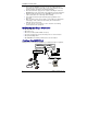
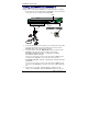
MultiVOIP FX Cabling Guide Cabling the MVPFX2-4 & MVPFX2-8 Cabling involves connecting the MultiVOIP to your LAN and telephone equipment. 1. Connect the power cord supplied with your MultiVOIP to a live AC outlet and to the power connector on the back of the MultiVOIP. Grounding Screw Voice/Fax Channel Connections Channels 1-4 Left-Most; for MVPFX2-4/8 Channels 5-8 Right-Most; for MVPFX2-8 only Groun ding Cable RJ-45 Cable Default IP 192.168.2.1 Ether net FXS FXO RJ-11 Connectors PC IP 192.168.2.
MultiVOIP FX Cabling Guide configured identically, each channel is individually configurable. So, for example, some channels of a MultiVOIP might use the FXO interface and others the FXS. 5. Ensure that the unit is properly connected to earth ground by verifying that it is reliably grounded when mounted within a rack. This can be accomplished by connecting a grounding wire between the chassis grounding screw and a metallic object that will provide an electrical ground. 6.
2100090L