RouteFinder® SOHO SOHO Security Appliance EDGE Models RF825-E, RF825-E-AP CDMA Models RF825-C-Nx, RF825-C-Nx-AP User Guide
Copyright and Technical Support RouteFinder SOHO Security Appliance User Guide Models: EDGE Models RF825-E, RF825-E-AP CDMA Models RF825-C-Nx, RF825-C-Nx-AP Document Product Number S000422B, Revision B Copyright © 2007-2009 This publication may not be reproduced, in whole or in part, without prior expressed written permission from MultiTech Systems, Inc. All rights reserved. Multi-Tech Systems, Inc.
Table of Contents Contents Chapter 1 – Introduction and Product Description ................................................................................. 6 Features.................................................................................................................................................. 6 Key Features .................................................................................................................................... 6 Feature Details ..............................
Table of Contents Administration > System Setup ...................................................................................................... 34 Administration > Administrative Access ......................................................................................... 36 Administration > System Logs ....................................................................................................... 38 Administration > Remote Syslog ...........................................................
Table of Contents RouteFinder Troubleshooting ............................................................................................................... 85 CDMA Troubleshooting ........................................................................................................................ 87 EDGE Troubleshooting ......................................................................................................................... 87 Chapter 7 – Frequently Asked Questions......................
Chapter 1 – Introduction and Product Description Chapter 1 – Introduction and Product Description Welcome to the world of Internet security. Your Multi-Tech RouteFinder SOHO Internet security appliance, model RF825-C/E, and the RouteFinder wireless Internet security appliance, model RF825-C/E-AP, are ideal for the small office or home office (SOHO) that needs secure access to a corporate LAN. The RF825 CDMA/EDGE-AP builds offer secure 802.11b/g Wi-Fi® wireless connectivity.
Chapter 1 – Introduction and Product Description Feature Details • • Secure VPN Connections. The RouteFinder SOHO security appliance uses the IPSec or PPTP industry standard protocol, data encryption, and the Internet to provide high-performance, secure VPN connections. For LAN connectivity, the RouteFinder SOHO security appliance utilizes the IPSec protocol to provide up to 15 tunnels with strong 3DES or AES encryption using IKE and PSK key management.
Chapter 1 – Introduction and Product Description • Optional VPN Client Software. Multi-Tech provides easy-to-use IPSec VPN client software that transparently secures Internet communications anytime, anywhere. VPN client software is ideal for business users who travel frequently or work from home providing secure remote access through the RouteFinder security appliance for applications such as remote access, file transfer, e-mail, Web browsing, messaging or IP telephony.
Chapter 1 – Introduction and Product Description Safety Warnings Ethernet Ports Caution The Ethernet ports are not designed to be connected to a Public Telecommunication Network. Handling Precautions All devices must be handled with certain precautions to avoid damage due to the accumulation of static charge.
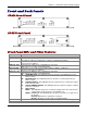
Chapter 1 – Introduction and Product Description Front and Back Panels CDMA Front Panel EDGE Front Panel Front Panel LEDs and Other Features LEDs Power Status Description Lights when power is being supplied to the RouteFinder. When functioning normally, the LED blinks. The LED is a solid light when the RouteFinder is booting up, saving the configuration, restarting, or updating the firmware. Lights when a successful connection to the 100BaseT LAN is established.
Chapter 1 – Introduction and Product Description Signal Strength LEDs Reference Chart Signal Strength AT Commands: The EDGE query signal strength command is: AT+CSQ Response Example: +CSQ: xx, 99 (For xx, see the values chart below) The CDMA query signal strength command is: AT+CCED Response Example: +CSQ:16, 99 +CCED:0,0,384,26,2,6,104,2513,2,17,xx,-45,-63 (For xx, see the values chart) Definition of xx Values The following table lists the xx values and explains how they correspond to the number of LEDs
Chapter 1 – Introduction and Product Description CDMA & EDGE Back Panel CDMA-AP & EDGE-AP Back Panel Back Panel Connectors Connector GSM/CDMA Antenna Connector Handset WAN LAN Ports +9 Volt to 32VDC Reset 802.11 Description Connector for the 2 dbi cellular antenna. Note: The antenna must be attached in order for the RouteFinder to be operational. Connector for a handset. The WAN (10/100BaseT) port connects the DSL modem or cable modem. There are 4 LAN ports.
Chapter 1 – Introduction and Product Description Application Example Multi-Tech Systems, Inc.
Chapter 1 – Introduction and Product Description RF825-AP Specifications These specifications are for the RF825-AP.
Chapter 1 – Introduction and Product Description CDMA Specifications The SocketModem CDMA meets the following specifications: Category Standard Bandwidth Data Speed Description CDMA2000 1xRTT Dual-band 800/1900 MHz CDMA Serial interface supporting DTE speeds to 230K Packet data up to 153.6K bps forward and reverse channels Circuit-switched data up to 14.
Chapter 1 – Introduction and Product Description Specifications for 802.11b/g Interface Specifications Description Network Standards IEEE 802.11b IEEE 802.11g 2.400-2.4835GHz Frequency Band Data Rate Media Access Control Channel IEEE 802.11b (auto-fallback): • CCK: 11, 5.5 Mbps • QPSK: 2 Mbps • BPSK: 1 Mbps IEEE 802.11g (auto-fallback): • OFDM: 54, 48, 36, 24, 18, 12, 9 and 6 Mbps CSMA/CA with ACK IEEE 802.11b Ch. 1 to 11 – North America Ch. 1 to 14 – Japan Ch. 1 to 13 – Europe ETSI Ch.
Chapter 2 – Cabling the RouteFinder Chapter 2 – Cabling the RouteFinder To use your RouteFinder make the appropriate connections to PCs, a cable or xDSL modem, and AC power. For AP models, attach the antennas. After your device is properly cabled, it must be configured. Basic cabling directions are included below. See Chapter 3 for basic configurations. See Chapter 4 for advanced configurations. RF825 Cabling 1.
Chapter 2 – Cabling the RouteFinder RF825-AP Cabling Follow the cabling procedures for RF825, and then attach the wireless antenna. See the Back Panel section earlier in this chapter for the location of the antenna connector. Note: The antenna must be attached in order for the RouteFinder to be operational.
Chapter 3 – Setting Up a Workstation and a Wireless Account Chapter 3 – Setting Up a Workstation and a Wireless Account Establishing TCP/IP Communication The following directions establish a TCP/IP connection at the workstation so the PC can communicate with the RouteFinder. The RouteFinders have built-in DHCP functionality, so you can set the PC to obtain a dynamic IP address. The following directions were written using a Windows 2000+ / XP operating system.
Chapter 3 – Setting Up a Workstation and a Wireless Account 4. The Local Area Connection Properties dialog box displays. • Select Internet Protocol [TCP/IP]. • Click the Properties button. 5. Once you click the Properties button, the following screen displays (below). To have your DCHP client obtain a dynamic IP address, click the Obtain an IP address automatically button. 6. Close out of the Control Panel. 7. Repeat these steps for each PC on your network.
Chapter 3 – Setting Up a Workstation and a Wireless Account Obtaining & Activating a Wireless Account You may want to use a wireless connection to the Internet in case your Ethernet WAN connection goes down. Before you can use the this feature, you must obtain a wireless account through a service provider and then activate the account. Activation Notices Please see the wireless account Activation Notices located on the MultiModem CD.
Chapter 3 – Setting Up a Workstation and a Wireless Account 10. Once you are logged in, you must setup the PPP functionality. Select Network Setup from the Menu bar, and then select PPP Cellular/Analog Backup when the Network Setup screen displays. The PPP Cellular/Analog Backup screen displays. Multi-Tech Systems, Inc.
Chapter 3 – Setting Up a Workstation and a Wireless Account 11. 12. 13. 14. 15. 16. 17. 18. 19. Enter the following on the PPP Cellular/Analog Backup screen to configure the PPP dialer: Status: Check this box to enable PPP. Dial-on-Demand: Select Disable (select disable to stay connected at all times). Idle time out: 0 (zero indicates that the connection will not disconnect) User Name: Enter your user name. There is no default. Password: Enter your password. There is no default.
Chapter 3 – Setting Up a Workstation and a Wireless Account Command Examples Verifying Signal Strength 1. In the command window: For EDGE and Verizon CDMA type the following command to query the signal strength: AT+CSQ Response Example: +CSQ: xx, 99 (For xx, see the values chart below) All other CDMA type the following command to query the signal strength: AT+CCED Response Example: +CSQ:16, 99 +CCED:0,0,384,26,2,6,104,2513,2,17,xx,-45,-63 (For xx, see tables below) 2.
Chapter 4 – Configuring the RouteFinder Chapter 4 – Configuring the RouteFinder Starting the RouteFinder Open a Web Browser Initial configuration is required in order for you to begin operation. The browser-based interface eases configuration and management. Note: Be sure that the RouteFinder is cabled and that the power is connected as shown in Chapter 2. Bring up a Web browser on the PC. 1. Type the default gateway address line: http://192.168.2.1 2. Press Enter.
Chapter 4 – Configuring the RouteFinder Web Management Software Opens This is the Home screen from which you can access all setup functions. Note: Only the top portion of the Home screen is shown here. Navigating the Screens Before using the software, you may find the following information about navigating through the screens and the structuring of the menus helpful. Menu Bar Sub Menu Other Options Screen Name Input Area Menu Bar See menu categories and their submenus below. Multi-Tech Systems, Inc.
Chapter 4 – Configuring the RouteFinder Sub-Menus Each Menu Bar selection has its own sub-menu, which displays on the left side of the screen. When you click one of the Main Menu choices, the first screen listed in the sub-menu displays. You can choose other sub-menu options/screens by clicking on your sub-menu choice. This is an example of the Administration sub-menu. It displays when you click Administration.
Chapter 4 – Configuring the RouteFinder Configuring the RouteFinder Using the Wizard Setup Basic Configuration Using the Setup Wizard Use the Wizard Setup for Quick Configuration A quick way to configure the RouteFinder is to use the Wizard Setup. The Wizard Setup can be opened by clicking the words Wizard Setup located under the Web Management software’s menu bar. The information entered here will default to other screens that require this information.
Chapter 4 – Configuring the RouteFinder Configuring the RouteFinder Using the Wizard Setup The Wizard Setup Screen Using the Wizard Setup is a quick way to enter the basic configuration parameters to allow communication between the LAN workstation(s) and the Internet. Important Note: An initial configuration must be completed for each type of RouteFinder functions: firewall configuration, LAN-to-LAN configuration, a LAN-to-Remote Client configuration.
Chapter 4 – Configuring the RouteFinder Configuring the RouteFinder Using the Wizard Setup ISP Settings Select the way the IP Address should be assigned for the WAN link. The default is DHCP Client. When you select Static IP or PPPoE, the input fields change. • WAN DHCP Client Choice DHCP (Dynamic Host Configuration Protocol) is a protocol that allows individual devices on an IP network to get their own network configuration information (IP address, subnet mask, broadcast address, etc.
Chapter 4 – Configuring the RouteFinder Configuring the RouteFinder Using the Wizard Setup • WAN PPPoE Choice PPPoE (Point-to-Point over Ethernet) is a specification for connecting multiple computer users on an Ethernet local area network to a remote site through DSL or cable modems or wireless connection to the Internet. The following fields display when you select PPPoE: User Name Enter the user name give by the ISP. Example: user1@xyz.com or user 1 Password Enter the user’s password.
Chapter 4 – Configuring the RouteFinder Configuring the RouteFinder Using the Wizard Setup • WAN PPPoE Choice (Continued) MTU A Maximum Transmission Unit (MTU) is the size (in bytes) of the largest packet that can be passed onwards. The default for this field is 1412, which should be acceptable for most applications. To read more about MTU, see the following Web site: http://en.wikipedia.org/wiki/Maximum_transmission_unit Primary DNS In this field, enter a primary domain server name (DNS).
Chapter 4 – Configuring the RouteFinder Save & Restart Button Under Menu Bar Select the Save and Restart button located just under the menu bar. The Save and Restart screen displays. Save to Flash Memory If a connection is established, then the settings have been entered correctly and your basic configuration is now complete. Now, you must save your settings to the Flash Memory; this saves the current settings in the flash prom and prevents settings from getting lost at the next power up.
Chapter 5 – Using the RouteFinder's Web Management Software Administration > System Setup Chapter 5 – Using the RouteFinder's Web Management Software This chapter takes you screen-by-screen through the software. Note: The antenna must be attached in order for the RouteFinder to be operational. Administration Administration > System Setup In the Administration part of the software, you can set the RouteFinder general system-based parameters.
Chapter 5 – Using the RouteFinder's Web Management Software Administration > System Setup User Name If your mail server accepts connection only after a user name and password are authenticated, enter your user name. Password If your mail server accepts connection only after a user name and password are authenticated, enter your password. Email Address Enter the email address of the administrator who will receive the email notifications. Enter it in proper user@domain format. Click Save.
Chapter 5 – Using the RouteFinder's Web Management Software Administration > Administrative Access Administration > Administrative Access The networks and hosts that are allowed to have administrative access are selected on this screen. This is a good way to regulate access to the configuration tools. Screen Note: If you are using the AP build and you select Independent Subnet on the Network Setup > Wireless LAN screen, WLAN Interface is available in the drop down list box of Available Networks/Hosts.
Chapter 5 – Using the RouteFinder's Web Management Software Administration > Administrative Access Change Password You should change the password immediately after initial installation and configuration, and also change it regularly thereafter. Old Password, New Password, Confirmation To change the password, enter the existing password in the Old Password field, enter the new password into the New Password field, and confirm your new password by re-entering it into the Confirmation entry field.
Chapter 5 – Using the RouteFinder's Web Management Software Administration > System Logs Administration > Remote Syslog Administration > System Logs Screen Note: PPP Dial Backup Logging is available on the AP build only. To enable the RouteFinder System Logs, place a checkmark across from the log you want enabled. Then click the Save button. Administration > Remote Syslog Note: Enabling Remote Syslog logging will slow down the performance of the RouteFinder.
Chapter 5 – Using the RouteFinder's Web Management Software Administration > SNTP Client Administration > SNTP Client SNTP (Simple Network Time Protocol) is an internet protocol used to synchronize the clocks of computers on the network. Clicking the SNTP Client check box enables the firewall to act as a SNTP client. SNTP Configuration General Configuration SNTP Client Enable or disable the SNTP Client to contact the configured server on the UDP port 123 and set the local time. Default is Disable.
Chapter 5 – Using the RouteFinder's Web Management Software Administration > SNTP Client Time Zone Configuration Time Zone Enter your time zone. Default = UTC (Universal Coordination). See the following Web site for Time Zone information: http://wwp.greenwichmeantime.com/info/timezone.htm Time Zone Offset Enter +/- hh:mm. Default = +00:00. Offset is the amount of time varying from the standard time of a Time Zone. Daylight Configuration Daylight Saving Enables/disables Daylight Saving mode.
Chapter 5 – Using the RouteFinder's Web Management Software Administration > Tools Administration > Tools There are three tools that can help you test and maintain network connections and RouteFinder functionality. Ping and Trace Route test the network connections on the IP level.
Chapter 5 – Using the RouteFinder's Web Management Software Administration > Tools Administration > Factory Defaults Trace Route Trace Route is a tool for finding errors in the network routing. It lists each router’s addresses on the way to remote systems. If the path for the data packets is temporarily unavailable, the interruption is indicated by asterisks (*). After a number of tries, the attempt is aborted.
Chapter 5 – Using the RouteFinder's Web Management Software Networks & Services > Network Configuration Networks & Services Networks & Services > Network Configuration The names, addresses, and network masks or hosts are defined here. Edit and Delete options are used for editing or deleting the networks/hosts. However, the name of the network/host cannot be edited. The Edit link has to be clicked in order to change the address or mask entries.
Chapter 5 – Using the RouteFinder's Web Management Software Networks & Services > Network Configuration Network Configuration Fields Name Enter the name of network or host you want added to the list. This name has to unique; in other words, it should not be present in the displayed list. A space cannot be used in the name; it is considered an invalid character. IP Address Enter the IP address of the new network or host. The same address-mask pair should not be present in the displayed list.
Chapter 5 – Using the RouteFinder's Web Management Software Networks & Services > Service Configuration Networks & Services > Service Configuration On this screen you can specify the standard set of well known services available on the system. These services enable the configuration of the user defined services. The options to Delete or Edit a service after it has been defined and added are available by using the table at the bottom of the screen.
Chapter 5 – Using the RouteFinder's Web Management Software Networks & Services > Service Configuration Service Configuration Name Enter the name of network or host you want added to the list. This name has to unique; in other words, it should not be present in the displayed list. A space cannot be used in the name; it is considered an invalid character. After you have entered the name, click the Add button. Protocol Select from the following protocols: TCP, UDP, TCP & UDP, ICMP, AH, and ESP.
Chapter 5 – Using the RouteFinder's Web Management Software Network Setup > IP Settings Network Setup Network Setup > IP Settings Network > IP Settings Screen Multi-Tech Systems, Inc.
Chapter 5 – Using the RouteFinder's Web Management Software Network Setup > IP Settings LAN IP Address 192.168.2.1 defaults into this field. Subnet Mask 255.255.255.0 defaults into this field. These should be acceptable for your site. WAN Select the way the IP Address should be assigned for the WAN link. The default is DHCP Client. When you select Static IP or PPPoE, the input fields change.
Chapter 5 – Using the RouteFinder's Web Management Software Network Setup > IP Settings WAN Choice: PPPoE PPPoE (Point-to-Point Protocol over Ethernet) is a specification for connecting multiple users on an Ethernet local area network to a remote site through DSL or cable modems or wireless connection to the Internet. The following fields display when you select PPPoE: User Name Enter the ADSL user name give by the ISP. Example: user1@xyz.com or user 1 Password Enter the user’s password.
Chapter 5 – Using the RouteFinder's Web Management Software Network Setup > Wireless LAN Network Setup > Wireless LAN Screen Note: This screen applies to the RF825-AP only. Use the following screen to setup the wireless LAN (WLAN) interfaces. WLAN Settings Name (SSID) An SSID is the name of a wireless local area network (WLAN). All wireless devices on a WLAN must employ the same SSID in order to communicate with each other.
Chapter 5 – Using the RouteFinder's Web Management Software Network Setup > Wireless LAN > WLAN Security Network Setup > Wireless LAN > WLAN Security Screen Note: This screen applies to RF825-AP only. Select the Security option for the Wireless LAN network. The default is Disable. WLAN Security Select Security Select the Security option from the drop down box for the Wireless LAN network. Each selection will display a separate set of input fields.
Chapter 5 – Using the RouteFinder's Web Management Software Network Setup > Wireless LAN > WLAN Security WEP Key The WEP Key is used to encrypt/decrypt the data. Enter the Key value based on the WEP Encryption Strength. WEP Key to Index The Key Index shows in which order the WEP Key values are stored. Example: WEP Key Index: 1 This means that the WEP Key is stored as the first WEP Key in the configuration. • Security Selections – WPA-PSK and WPA2-PSK This is the WAP-PSK screen.
Chapter 5 – Using the RouteFinder's Web Management Software Network Setup > Wireless LAN > WLAN Security Idle Timeout (for WPA2-PSK only) Enter the amount of idle time in minutes that will pass before the Key will timeout (for the WPA2-PSK Key only). Group Key Rekeying The encryption keys are automatically changed (called rekeying) and authenticated between devices after a specified period of time or after a specified number of packets has been transmitted. This is called the rekey interval.
Chapter 5 – Using the RouteFinder's Web Management Software Network Setup > Wireless LAN > WLAN Client Filter Network Setup > Wireless LAN > WLAN Client Filter Screen Note: This screen applies to the RF825-AP only. WLAN Client Filter The WLAN Client Filter is used to Allow/Reject the wireless station's association with the Access Point. Access Control Status Check this box to enable Access Control on the WLAN.
Chapter 5 – Using the RouteFinder's Web Management Software Network Setup > Advanced IP Settings Network Setup > Advanced IP Settings Specify the Host Name, the External Server for the system and the IP Aliases for each of the interfaces. Host Name The Host Name must be defined for your RouteFinder. The name must be entered into this format: FIREWALL.mydomain.com. Click the Save button. Example: Localhost.xscale.com WINS Server Enter a name for the WINS Server. Click the Add button.
Chapter 5 – Using the RouteFinder's Web Management Software Network Setup > PPP Cellular/Analog Backup Network Setup > PPP Cellular/Analog Backup The PPP link is used as a backup link to the WAN interface. If the Internet Keep-alive URLs (see below) are not reachable through the WAN Ethernet interface, the PPP backup link automatically comes up and the system regains its connection to the ISP. PPP Client for Cellular/Analog Modem Backup Status Check this box to enable PPP Dial Backup on WAN interface.
Chapter 5 – Using the RouteFinder's Web Management Software Network Setup > PPP Cellular/Analog Modem Backup User Name Enter the user name to authenticate the RouteFinder with the ISP. The User Name is optional. Password Enter the user password. These special characters cannot be used: <, >. The Password is optional. Baud Rate Select the serial baud rate from the drop down box. Select 115200 for CDMA; 230400 for EDGE.
Chapter 5 – Using the RouteFinder's Web Management Software Network Setup > Dynamic DNS Network Setup > Dynamic DNS The DDNS Client is used to update the IP address of the modem/router in a DDNS server for the configured domain name whenever the IP Address changes, thus, leaving the domain name to be pointing to the current IP Address of the modem/router all the time. WAN Dynamic DNS Client Check the box to enable DDNS Client. Default = Disable.
Chapter 5 – Using the RouteFinder's Web Management Software Network Setup > Dynamic DNS Use Wildcard If this option is enabled, subdomains of the registered domain will also be resolved to the same IP address. For example, if test.dyndns.org has been registered and the IP address it is resolved to is a.b.c.d, all subdomains like dns.test.dyndns.org will also get resolved to a.b.c.d. However, this will work only if the dynamic DNS server supports this option.
Chapter 5 – Using the RouteFinder's Web Management Software Network Setup > Static Routes Network Setup > IP Masquerading Network Setup > Static Routes Routing information is used by every computer connected to a network to identify whether it is sending a data packet directly to the firewall or passing it on to another network. This screen can be used to describe the networks to be reached through a configured gateway.
Chapter 5 – Using the RouteFinder's Web Management Software Network Setup > SNAT Network Setup > SNAT The SNAT (Source Network Address Translation) process allows attaching private networks to public networks. SNAT is used when you want to have a LAN using a private IP network to be connected to the internet via a firewall. Since the private IP addresses are not routed on the internet, you have to apply SNAT on the firewall’s external interface.
Chapter 5 – Using the RouteFinder's Web Management Software Network Setup > DNAT Network Setup > DNAT The DNAT (Destination Network Address Translation) process allows placing servers within the protected network and making available for a certain service to the outside world. Normally, the RouteFinder has a network server running in the LAN providing a network service with an address in the specified range, and wants this service accessible to the outside world.
Chapter 5 – Using the RouteFinder's Web Management Software Packet Filters > Packet Filter Rules Packet Filters Packet Filter > Packet Filter Rules Packet filters are used to set firewall rules which define what type of data traffic is allowed across the RouteFinder's firewall. There are certain System Defined Rules that exist by default. In addition, you can specify whether particular packets are to be forwarded through the RouteFinder system or filtered.
Chapter 5 – Using the RouteFinder's Web Management Software Packet Filters > Packet Filter Rules Important Note about the Order of Rules: The order of the rules in the table is essential for the correct functioning of the firewall. By clicking the Move button, the order of execution can be changed. In front of rule to be moved, enter the line number that indicates where the rule should be placed. Confirm by clicking OK. By default, new rules are created at the end of the table.
Chapter 5 – Using the RouteFinder's Web Management Software Packet Filters > Advanced Filters Packet Filters > Advanced Filters This section allows configuration of some advanced filter settings. H323 Packets Passthrough Check this box to enable the forwarding of H323 packets across the firewall. PPTP Packets Passthrough Check this box to enable PPTP Packets Passthrough (PPTP NAT support). This includes two features: • Server behind the firewall and clients on the Internet – DNAT of PPTP packets.
Chapter 5 – Using the RouteFinder's Web Management Software Packet Filters > ICMP Packet Filter > ICMP ICMP (Internet Control Message Protocol) is used to test the network connections and the functionality of the RouteFinder. It is also used for diagnostic purposes. ICMP-on-Firewall and ICMP Forwarding always apply to all IP addresses (Any). When these are enabled, all IP hosts can PING the RouteFinder (ICMP-on-Firewall) or the network behind it (ICMP Forwarding).
Chapter 5 – Using the RouteFinder's Web Management Software VPN > IPSec VPN (Virtual Private Network) VPN > IPSec Introduction to Virtual Private Networks A Virtual Private Network (VPN) is a secure communication connection via an insecure medium – usually the Internet. A VPN is useful in situations where information is sent and received via the Internet and it is important that no third party can read or change that information.
Chapter 5 – Using the RouteFinder's Web Management Software VPN > IPSec > Add IKE Connection Add an IKE Connection This section enables setting IPSec tunnels through an IKE connection. Add IKE Connection Connection Name Enter a text name that will identify the connection for you. Compression Check the compression checkbox to enable IPCOMP, the compression algorithm.
Chapter 5 – Using the RouteFinder's Web Management Software VPN > IPSec > Add IKE Connection Key Life The duration for which the IPSec SA should last is from successful negotiation to expiration. The default value is 28800 seconds and the maximum is 86400 seconds. Number of Retries Specify the number of retries for the IPSec tunnel. Enter zero for unlimited retries. Left Next Hop Next Hop is the address of the next device in a routing table’s path that moves a packet to it’s destination.
Chapter 5 – Using the RouteFinder's Web Management Software VPN > IPSec > Add Manual Connection Add a Manual Connection This section enables setting IPSec tunnels through manual connection. Add Manual Connection Connection Name Enter a text name that will identify the connection for you. Compression Check the compression checkbox to enable IPCOMP, the compression algorithm. Authentication Method Select the authentication algorithms to be used for the respective security services.
Chapter 5 – Using the RouteFinder's Web Management Software VPN > IPSec > Add Manual Connection Left Next Hop Next Hop is the address of the next device in a routing table’s path that moves a packet to it’s destination. This setting can be configured or left as a static value: 0.0.0.0. When not configured, the value is set to the Gateway of the Box/Gateway configured on the Interface/Right IP. The selection is based on the Left and Right IP.
Chapter 5 – Using the RouteFinder's Web Management Software VPN > PPTP VPN > PPTP PPTP (Point-to-Point Tunneling Protocol) is a tunneling protocol meant for tunneling IP packets and non-IP packets through the IP only network (the Internet). PPTP offers connections to PPTP clients so that they can become virtual members of the IP pool owned by the PPTP server. In effect, these clients become virtual members of the local subnet regardless of their real IP address.
Chapter 5 – Using the RouteFinder's Web Management Software VPN > PPTP User Authentication Authentication Type Select the desired user Authentication Type and click the Save button: • Local – Authentication type used when local users have individual access rights. • RADIUS – Authentication type used when access rights comes from a central server for user authentication. Local or RADIUS Local Authentication Input User Name – Enter the user’s name in lowercase.
Chapter 5 – Using the RouteFinder's Web Management Software Proxy > HTTP Proxy Proxy While the packet filter filters the data traffic on a network level, the use of a Proxy (also called an Application Gateway) increases the security of the RouteFinder on the application level, as there is no direct connection between client and server. Proxy > HTTP Proxy The HTTP Proxy is a module built into the RouteFinder to redirect HTTP requests from the clients in the LAN to the Internet.
Chapter 5 – Using the RouteFinder's Web Management Software Proxy > Custom URL Filters Proxy > Custom Filters The custom URL list allows URLs to be filtered or forwarded by the RouteFinder. Custom URL lists are configured here. Sets of URLs to be forwarded/filtered for a particular network/host can also be configured. Default Action for Custom URL Lists Default Action The default action can be set to either Allow or Deny. Click the Save button to set the default action.
Chapter 5 – Using the RouteFinder's Web Management Software Proxy > DNS Proxy Proxy > DNS Proxy DNS Proxy is a module used to redirect DNS requests to name servers. This module supports a caching-only name server which will store the DNS entries for a specified item. So, when there is a query next time, the values will be taken from the cache and the response will be sent from the module itself. This will shorten the waiting time significantly, especially if it is a slow connection.
Chapter 5 – Using the RouteFinder's Web Management Software DHCP Server > LAN Subnet Settings DHCP Server DHCP Server > LAN Subnet Settings DHCP (Dynamic Host Configuration Protocol) is a protocol that allows individual devices on an IP network to get their own network configuration information (IP address, subnet mask, broadcast address, etc.) from a DHCP server. The overall purpose of the DHCP is to make it easier to administer a large network.
Chapter 5 – Using the RouteFinder's Web Management Software DHCP Server > LAN Fixed Addresses DHCP Server > WLAN Subnet Settings DHCP Server > WLAN Fixed Addresses DHCP Server > LAN Fixed Addresses The DHCP server can be made to assign a fixed IP address for a particular system by identifying the MAC address. This binding can be made permanent by configuring it here.
Chapter 5 – Using the RouteFinder's Web Management Software Utilities > Backup Utilities > Firmware Upgrade Utilities Utilities > Backup The Backup function lets you save the RouteFinder settings on a local hard disk or exported to a remote client. With a backup file, you can set a recently installed RouteFinder to the identical configuration level as an existing RouteFinder. This is also useful in case there is a problem with your new settings.
Chapter 5 – Using the RouteFinder's Web Management Software Statistics & Logs > System Information Statistics & Logs Statistics & Logs > System Information The System Information screen provides the following information: 1. System Information • Product Modem Number • Firmware Version • MAC Address 2. Live Details • Date and Time • System Uptime • Memory Utilization • Free Memory Blocks Multi-Tech Systems, Inc.
Chapter 5 – Using the RouteFinder's Web Management Software Statistics & Logs > Network Interface Details Statistics & Logs > Packet Filter Log Statistics & Logs > Network Interface Details The screen provides information on the network traffic on all the interfaces.
Chapter 5 – Using the RouteFinder's Web Management Software Statistics & Logs > IPSec Live Log Statistics & Logs > PPTP Live Log Statistics & Logs > DHCP Server Live Log Statistics & Logs > IPSec Live Log IPSec Live Log gives information on connections that are active. IPSec Statistics gives statistics of transmitted and received packets/bytes. Statistics & Logs > PPTP Live Log The PPTP Live Log gives information about users who are logged in into the PPTP server at any given point in time.
Chapter 5 – Using the RouteFinder's Web Management Software Statistics & Logs > PPP Cellular/Analog Log Statistics & Logs > WLAN Client Live Log Statistics & Logs > PPP Cellular/Analog Log The PPP Cellular/Analog Log gives information about the modem connection: Statistics & Logs > WLAN Client Live Log The WLAN Client Live Log lists current WLAN connections. Multi-Tech Systems, Inc.
Chapter 5 – Using the RouteFinder's Web Management Software Statistics & Logs > Log Traces Statistics & Logs > Log Traces Log Traces provides information about the following connections. Logs DHCP Client Log Traces Click the Show button to view connection events between the DHCP Client and the DHCP Server. PPPoE Client Log Traces Click the Show button to view connection events between the PPPoE Client and the DHCP Server. PPTP Log Traces Click the Show button to view PPTP connection events.
Chapter 6 – Troubleshooting Chapter 6 – Troubleshooting This chapter provides a list of common problems encountered while installing, configuring, or administering the RouteFinder. In the event you are unable to resolve your problem, see the copyright page for information about contacting our Technical Support representatives. RouteFinder Troubleshooting Other computers can connect to the network device, but my computer can’t.
Chapter 6 – Troubleshooting Sometimes when I try to use the Internet or get my mail, the application can’t connect to the Internet immediately. • The most common reason for this is not due to a problem or error. If you are the first person to make a connection to the Internet through the RouteFinder, there will be a delay when the Dial-On-Demand function automatically makes the connection and logs on to your ISP. Subsequent users will be able to use the connection you’ve established without a delay.
Chapter 6 – Troubleshooting CDMA Troubleshooting I have the N1 model and I can’t get it activated on my carrier's network. • You will need to configure the MDN, MIN, and maybe more settings such as the primary and secondary channels, and the Home SID and UID. • The commands are: +WMDN (MDN), +WIMI (MIN), +WPCC (Primary channel), +WSCC (Secondary channel), +WSID (SID and UID), and +WCMT=1 (to store changes) • You may need more settings set, so you may need to use the WPST provisioning tool application.
Chapter 7 – Frequently Asked Questions Chapter 7 – Frequently Asked Questions RouteFinder FAQs Where is the RouteFinder installed on the network? In a typical environment, the RouteFinder is installed between the Cable/DSL Modem and the LAN. The wireless RouteFinder has the modem as part of the device. Plug the WAN of the RouteFinder into the Cable/DSL modem Ethernet port. Does the RouteFinder support IPX or AppleTalk? No.
Chapter 7 – Frequently Asked Questions Does the RouteFinder replace a modem? That is, is there a cable or DSL modem in the router? No. The RouteFinder must work in conjunction with a cable or DSL modem. Which modems are compatible with the router? The RouteFinder is compatible with any cable modem or DSL modem that supports Ethernet. How do I access the RouteFinder's setup pages with a Mac? The RouteFinder's setup pages are accessible to the Mac through a browser. Use the default address 192.168.2.1.
Chapter 7 – Frequently Asked Questions EDGE FAQs What are the different carriers APNs? • Each carrier will most likely have a different APN from another. The best way to know which APN you have is to contact the provider. • Here are some common APNs that we know of: AT&T – “PROXY”, “INTERNET”, “PUBLIC” T-Mobile – “INTERNET2.VOICESTREAM.COM”, “INTERNET3.VOICESTREAM.COM” Cingular – “ISP.CINGULAR” , username = “ispda@cingulargprs.com” , password = “CINGULAR1” Rogers AT&T – “INTERNET.
Appendix A – Table of Commonly Supported Subnets Appendix A – Table of Commonly Supported Subnet Addresses This table lists commonly supported Subnets organized by Address. 255.255.255.128 /25 255.255.255.192 /26 255.255.255.224 /27 255.255.255.240 /28 255.255.255.248 /29 Network Number N.N.N.0 N.N.N.128 Hosts Available N.N.N.1-126 N.N.N.129-254 Broadcast Address N.N.N.127 N.N.N.255 Network Number N.N.N.0 N.N.N.64 N.N.N.128 N.N.N.192 Hosts Available N.N.N.1-62 N.N.N.65-126 N.N.N.129-190 N.N.N.
Appendix A – Table of Commonly Supported Subnets 255.255.255.252 /30 N.N.N.176 N.N.N.184 N.N.N.192 N.N.N.200 N.N.N.208 N.N.N.216 N.N.N.224 N.N.N.232 N.N.N.240 N.N.N.248 N.N.N.177-182 N.N.N.185-190 N.N.N.193-198 N.N.N.201-206 N.N.N.209-214 N.N.N.217-222 N.N.N.225-230 N.N.N.233-238 N.N.N.241-246 N.N.N.249-254 N.N.N.183 N.N.N.191 N.N.N.199 N.N.N.207 N.N.N.215 N.N.N.223 N.N.N.231 N.N.N.239 N.N.N.247 N.N.N.255 Network Number N.N.N.0 N.N.N.4 N.N.N.8 N.N.N.12 N.N.N.16 N.N.N.20 N.N.N.24 N.N.N.28 N.N.N.32 N.N.
Appendix B – Antenna for the Wireless RouteFinder Appendix B – Antenna for the Wireless RouteFinder The Access Point Antenna Your ship kit for the wireless RouteFinder includes a 2.4 GHz 5dBi SWI-Reverse-F Swivel Antenna. Important Notes: • The antenna for this product must be a reverse polarity SMA antenna. • The antenna must be attached in order for the RouteFinder access point to be operational.
Appendix B – Antenna for the Wireless RouteFinder The Wireless Antenna The antenna sub-system and integration in the application is a major issue: Choice of antenna (type, length, performances, thermal resistance, etc.) These elements could affect GSM performances such as sensitivity and emitted power. GSM, EDGE, and CDMA Antenna The integrated modem antenna connector is a SMA connector.
Appendix C – Waste Electrical and Electronic Equipment Directive (WEEE) Appendix C – Waste Electrical and Electronic Equipment Directive (WEEE) Waste Electrical and Electronic Equipment (WEEE) Directive The WEEE directive places an obligation on manufacturers, distributors and retailers to take-back electronic products at the end of their useful life.
Glossary Glossary A AES AES (Advanced Encryption Standard), also known as Rijndael, is a block cipher adopted as an encryption standard. Authentication The process of determining the identity of a user attempting to access a system and the process of verifying that a particular name really belongs to a particular entity. Asynchronous A method of transmitting data which allows characters to be sent at irregular intervals.
Glossary Dynamic Routing Routing is the process of selecting the correct path for a message. Dynamic routing adjusts automatically to changes in network topologies or traffic. E Encryption In general use, the transformation of data into a form unreadable by anyone without a secret decryption key. Its purpose is to ensure privacy by keeping the information hidden from anyone for whom it is not intended. Ethernet A LAN (Local Area Network) protocol developed by Xerox and DEC.
Glossary IP Addresses A computer on the Internet is identified by an IP Address. A computer’s IP address is like a telephone number. It identifies one address or in this case one computing device. Every computer or device on the network must have a different IP address. An IP address consists of four groups of numbers called octets, which are separated by periods. For example, 213 .0.0.1 is an IP address. An IP address consists of a network portion and a host portion.
Glossary Network Address The network portion of an IP address. For a class A network, the network address is the first byte of the IP address. For a class B network, the network address is the first two bytes of the IP address. For a class C network, the network address is the first three bytes of the IP address. In each case, the remainder is the host address. In the Internet, assigned network addresses are globally unique.
Glossary Static Routing Involves the selection of a route for data traffic on the basis of routing options preset by the network administrator. Subnet A portion of a network that shares a common address component. On TCP/IP networks, subnets are all devices whose IP Addresses have the same prefix. For example, all devices with IP addresses starting with 213.0.0 are part of the same subnet. Subnet Mask / IP Address Mask Subnet mask is what is used to determine what subnet an IP address belongs to.
Glossary WLAN (Wireless Local Area Network) A LAN without wires. WPA-PSK Wi-Fi Protected Access (WPA and WPA2) is a class of systems to secure wireless (Wi-Fi) computer networks. WPA is designed for use with an IEEE 802.1x authentication server, which distributes different keys to each user. However, it can also be used in a less secure "pre-shared key" (PSK) mode, where every user is given the same passphrase.
Index Index 8 802.11b/g specifications................................... 16 A Administration > Administrative Access ........... 36 Administration > Factory Defaults .................... 42 Administration > Remote Syslog ...................... 38 Administration > SNTP Client .......................... 39 Administration > System Logs ......................... 38 Administration > System Setup ........................ 34 Administration > Tools ..................................... 41 Administrative Access .
G Gateway Definition ........................................... 97 Glossary ........................................................... 96 H Handling Precautions ......................................... 9 Handset Connector .......................................... 12 HTTP port ......................................................... 37 HTTP Proxy ...................................................... 74 Humidity ........................................................... 14 I ICMP ....................
TCP & UDP .................................................. 46 Protocol Definition ............................................ 99 Protocols .......................................................... 46 Proxy > Custom URL Filters ............................ 75 Proxy > DNS .................................................... 41 Proxy > DNS Proxy .......................................... 76 Proxy > HTTP Proxy ........................................ 74 R Radio Characteristics .............................