
User guide

RouteFinder MTASR3 Quick Start Guide
Changing Shunt Positions
Table 3 provides the procedure for moving the link shunts before
connecting the RouteFinder to an external composite link device
that has a V.35 interface.
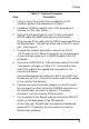
Table 3. V.35 Shunt Procedure
Step Procedure
1 Ensure that the external power supply is disconnected
from the RouteFinder.
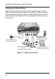
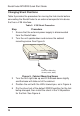
2 Turn the unit upside down and remove the cabinet
mounting screw. See Figure 5.
Enclosure Mounting
Screw (center, back)
T
e
c
h
Systems
®
Figure 5. Cabinet Mounting Screw
3 Turn the unit right side up and tilt the back down slightly
and the base will slide out of the cabinet.
4 Position the unit with the LEDs toward you, as in Figure 6.
5 Pry the shunt out of the default RS232 position for the link
being changed, then install the shunt in the V.35 position
for that link. See Figure 6.
10