
User's Manual

RPT 633
TM1184 Issue 1 AL1 (May 1997) Page 1 - 1
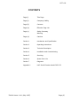
SECTION 1
INTRODUCTION AND SPECIFICATION
CONTENTS:
1. INTRODUCTION
2. ROLE OF THE TRANSMITTER
4. PHYSICAL CONSTRUCTION
SPECIFICATIONS
5. Transmitter
6. Connectors
7. Physical Characteristics
8. Operational Enviroment
9. Power Supply
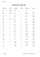
10. CRYSTAL FREQUENCY CALCULATION
_______________________
INTRODUCTION
1. Sections 1 to 7 of this manual outline the installation and operation of the Radio
Paging Transmitter model RPT 633. Appendix 1 details the Serial Encoder model RPE
673 and provides appropriate cross references to the main part of this manual
(Sections 1 to 7) where functionality is common.
ROLE OF THE TRANSMITTER
2. The transmitter is designed for operation with the RPE 340-series of telephone coupled
encoders, or from the encoder output of the Access 3000, which together provide radio
coverage with speech for smaller sites. The RPT 633 operates in the UHF band
(420MHz to 470MHz), divided into three sub-bands, and has an output of 2.5 Watts.
3. Digital control reduces the wiring between the encoder and transmitter to a single pair
for tone and display systems. A four wire connection is required for speech systems.