Installing, Operating & Maintaining MUNCHKIN™ HIGH EFFICIENCY HEATER with the “925” Controller WARNING If the information in this manual is not followed exactly, a fire or explosion may result causing property damage, personal injury or loss of life. Do not store or use gasoline or other flammable vapors and liquids in the vicinity of this or any other appliance. WHAT TO DO IF YOU SMELL GAS • Do not try to light any appliance. • Do not touch any electrical switch: do not use any phone in your building.
USING THIS MANUAL USING THIS MANUAL SPECIAL ATTENTION BOXES Throughout this manual you will see these special attention boxes similar to this one, which are intended to supplement the instructions and make special notice of potential hazards. These categories mean, in the judgement of Heat Transfer Products, Inc.: NOTICE Heat Transfer Products manufactures both ASME and Non-ASME boilers. It is the responsibility of the installer that the correct model has been selected for jurisdiction requirements.
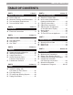
TABLE OF CONTENTS TABLE OF CONTENTS A B C D PART 1 . . . . . . . . . . . . . . . . . . . . . .4 thru 8 PART 6 . . . . . . . . . . . . . . . . . . . .34 thru 37 GENERAL INFORMATION START UP PROCEDURES How It Operates . . . . . . . . . . . . . . . . . .4 Munchkin Ratings and Dimensions . . .4 Pre-installation Requirements . . . . . . .8 Pressure Relief Valve . . . . . . . . . . . . . .9 PART 2 . . . . . . . . . . . . . . . . . . . . .9 thru 11 ELECTRICAL A Electrical Connection . . . . . . . . . . .
GENERAL INFORMATION PART 1. GENERAL INFORMATION A. HOW IT OPERATES When the room thermostat calls for heat, the Munchkin control board will start the circulator and start to monitor the return temperature of the system before the heater will begin to heat the water. Once the controller has sensed a drop in the return water temperature below the temperature set point minus the differential set point, the heater will start to heat the water.
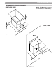
GENERAL INFORMATION RECOMMENDED SERVICE CLEARANCES (NOTE: The Munchkin is rated at zero clearance to combustibles.
GENERAL INFORMATION DIMENSIONS T50M/T80M Figure 1-3 6
GENERAL INFORMATION DIMENSIONS 80M Figure 1-4 140M/199M Figure 1-5 7
GENERAL INFORMATION C. PRE-INSTALLATION REQUIREMENT GENERAL 1. Munchkin Boilers are supplied completely assembled as packaged boilers. The package should be inspected for damage upon receipt and any damage to the unit should be reported to the shipping company and wholesaler. This boiler should be stored in a clean, dry area. 2. Carefully read these instructions and be sure to understand the function of all connections prior to beginning installation.
GENERAL INFORMATION / ELECTRICAL CAUTION The Munchkin is certified as an indoor appliance. Do not install the Munchkin outdoors or locate where it will be exposed to freezing temperature. This includes all related piping and components. If the Munchkin is subjected to flood water or submersed in water, the Munchkin must be replaced. Note: Service clearance of the Munchkin: See Section 1, Figures 1-1 and 1-2.
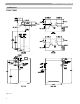
ELECTRICAL CAUTION Electrical wiring on the Incoming Power and Central Heating Circulator shall be connected directly to the intended connection source and not be connected together inside the electric box provided. An Electrical Short will result and the Control board will have to be replaced! If Electrical Requirements of the Central Heating Circulator exceeds 4 amps (or 3 amps on HA models only) please follow the wiring diagrams on Figures 2-1, 2-2 and 2-3 (this section).
ELECTRICAL DIAGRAM "A" DIAGRAM "B" WIRING DIAGRAM CONNECTING TO CIRCULATOR WIRING DIAGRAM WITHOUT CONNECTION TO CIRCULATOR T GRAY WHITE (NEUTRAL) T BLACK (HOT) GRAY T GREEN (GROUND) GRAY GRAY GREEN (GROUND) T NORMALLY OPEN THERMOSTAT CONNECTION BROWN (NEUTRAL) NORMALLY OPEN THERMOSTAT CONNECTION GREEN (GROUND) ORANGE (HOT) BLACK BROWN (NEUTRAL) WHITE (NEUTRAL) ORANGE (HOT) OR AN GE BR OW GR N EE N GREEN (GROUND) IMPORTANT NOTE: BE CERTAIN THAT THE ORANGE WIRE IS SECURELY CAPED.
GAS CONNECTION PART 3. GAS CONNECTION WARNING Failure to follow all precautions could result in fire, explosion or death! A. GAS CONNECTION The gas supply shall have a maximum inlet pressure of less than 14" water column (350 mm), ½ pound pressure (3.5 kPa), and a minimum of 3.5" water column. The entire piping system, gas meter and regulator must be sized properly to prevent pressure drop greater than 0.5" as stated in the National Fuel Gas Code. This information is listed on the rating plate.
GAS CONNECTION It is recommended that a soapy solution be used to detect leaks. Bubbles will appear on the pipe to indicate a leak is present. The gas piping must be sized for the proper flow and length of pipe, to avoid pressure drop. Both the gas meter and the gas regulator must be properly sized for the total gas load. If you experience a pressure drop greater than 1" WC, the meter, regulator or gas line is undersized or in need of service.
VENTING PART 4. VENTING DANGER It is extremely important to follow these venting instructions carefully. Failure to do so can cause severe personal injury, death or substantial property damage. A. APPROVED VENTING MATERIALS Exhaust Vent and Extensions in Plastic 2", 3" and 4" Pipe Schedule 40 or 80. 1. Non Foam Core PVC Pipe 2. Non Foam Core CPVC Pipe 3. Non Foam Core ABS Pipe Vent Piping must conform to following 1.
VENTING B. VENTING THE MUNCHKIN DANGER It is extremely important to follow these venting instructions exactly. Failure to do so can cause severe personal injury, death or substantial property damage. CAUTION The following are code restrictions for the location of the flue gas vent terminal. Compliance to these requirements doesn’t insure a satisfactory installation; good common sense must also be applied.
VENTING may require venting modifications (consult factory). The air inlet must be a minimum of 1' vertically above the maximum snow level. It is very important that there are no other vents, chimneys or air inlets in any direction for at least 4'. Mechanical draft vent terminal (see 10.8.1)* Mechanical draft vent terminal (see 10.8.2)* C 12 in. mi nim um Direct vent terminal clearance Minimum clearance, C Input (Btu/hr) 10,000 or less 10,001 to 50,000 Over 50,000 (see 10.8.3)* 4 ft.
VENTING Friction Loss Equivalent in Piping and Fittings Fittings or Piping 90 degree elbow 45 degree elbow Coupling air inlet tee Plastic Pipe concentric vent kit V500 or V1000 vent kit Equivalent Feet = = = = = = = 5 3 0 0 1 3 0 CAUTION Do not exceed the 85 foot maximum requirement (intake plus exhaust piping added together) including fitting allowance. Example: Installation requires the following material for both inlet and exhaust piping for the Munchkin Required: 4 Pcs.
VENTING DANGER The Munchkin is not intended to be common vented with any other existing appliance! D. HEATER REMOVAL FROM A COMMON VENT SYSTEM At the time of removal of an existing heater, the following steps shall be followed with each appliance remaining connected to the common venting system placed in operation, while the other appliances remaining connected to common venting system are not operating. 1. Seal any unused openings in the common venting system. 2.
VENTING DIAGRAMS FOR SIDEWALL VENTING **IMPORTANT NOTE: All vent pipes must be glued, properly supported and the exhaust must be pitched a minimum of a ¼" per foot back to the heater (to allow drainage of condensate). **IMPORTANT NOTE: All vent pipes must be glued, properly supported and the exhaust must be pitched a minimum of a ¼" per foot back to the heater (to allow drainage of condensate).
VENTING **IMPORTANT NOTE: All vent pipes must be glued, properly supported and the exhaust must be pitched a minimum of a ¼" per foot back to the heater (to allow drainage of condensate). Figure 4-3 **IMPORTANT NOTE: All vent pipes must be glued, properly supported and the exhaust must be pitched a minimum of a ¼" per foot back to the heater (to allow drainage of condensate).
VENTING DIAGRAMS FOR VERTICAL VENTING **IMPORTANT NOTE: All vent pipes must be glued, properly supported, and the exhaust must be pitched a minimum of a ¼" per foot back to the heater (to allow drainage of condensate). **IMPORTANT NOTE: All vent pipes must be glued, properly supported, and the exhaust must be pitched a minimum of a ¼" per foot back to the heater (to allow drainage of condensate).
PIPING PART 5. PIPING A. HYDRONIC PIPING WITH CIRCULATORS OR ZONE VALVES The Munchkin is designed to function in a closed loop 15 PSI System. To assure you that you have adequate pressure in the system, we have installed in the outlet manifold, a pressure switch that will not let the Munchkin operate without a minimum of 10 PSI water pressure. This assures you that if the system does have leak, the Munchkin will lock out (PRO on the display) before it damages the Stainless Steel Heat Exchanger.
PIPING 8. Install an Air Elimination Device on the system supply. 9. Install a drain valve at the lowest point of the system. Note: The Munchkin can not be drained completely of water without purging the unit with an air pressure 15 PSI. 10. The Safety Relief Valve is installed at the factory located on the right hand side of Munchkin. Pipe the discharge of safety relief valve to prevent injury in the event of pressure relief. Pipe the discharge to a drain.
PIPING C. FILL AND PURGE HEATING SYSTEM • • • • • Attach the hose to balance and purge hose connector or drain valve and run hose to nearest drain Close the other side of the balance and purge valve or the shut off valve after the drain. Open first zone balance and purge or drain valve to let water flow out the hose. If zone valves are used, open the valves one at a time manually. (Note: please check valve manufacturer’s instruction prior to opening valves manually, so as not to damage the valve.
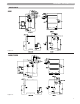
PIPING D. PIPING ILLUSTRATIONS Piping Symbol Legend circulator (w/ isolation flanges) pressure reducing valve circulator w/ integral flow check) diff.
PIPING Standard Munchkin boiler Retrofit piping (zoning with valves) Space heating mode Drawing 1A zone valves make-up water P1 flow bypass valve purging valves V1 OFF anti-scald mixing valve cold water T/P Munchkin boiler Super Stor indirect DHW tank NOTES: 1. 2. 3. 4. 5. 6. 7. 8. This drawing is meant to show system piping concept only. Installer is responsible for all equipment & detailing required by local codes.
PIPING Standard Munchkin boiler Retrofit piping (zoning with valves) Domestic water heating mode Drawing 1B OFF OFF OFF OFF zone valves make-up water P1 flow bypass valve purging valves V1 anti-scald mixing valve cold water T/P Munchkin boiler Super Stor indirect DHW tank NOTES: 1. 2. 3. 4. 5. 6. 7. 8. This drawing is meant to show system piping concept only. Installer is responsible for all equipment & detailing required by local codes.
PIPING Standard Munchkin boiler Preferred piping (zoning with valves) Space heating mode Drawing 2A zone valves make-up water P2 closely spaced tees differential pressure bypass valve purging valves V1 OFF anti-scald mixing valve cold water P1 T/P Munchkin boiler Super Stor indirect DHW tank NOTES: 1. 2. 3. 4. 5. 6. 7. 8. 9. This drawing is meant to show system piping concept only. Installer is responsible for all equipment & detailing required by local codes.
PIPING Standard Munchkin boiler Preferred piping (zoning with valves) Domestic water heating mode Drawing 2B OFF OFF make-up water OFF OFF zone valves P2 closely spaced tees differential pressure bypass valve V1 purging valves anti-scald mixing valve cold water P1 T/P Munchkin boiler Super Stor indirect DHW tank NOTES: 1. 2. 3. 4. 5. 6. 7. 8. 9. This drawing is meant to show system piping concept only. Installer is responsible for all equipment & detailing required by local codes.
PIPING Standard Munchkin boiler Preferred piping (zoning with circulators) Space heating mode Drawing 2C space heating zone circuit zone circulators make-up water closely spaced tees purging valves anti-scald mixing valve P2 cold water P1 T/P Munchkin boiler Super Stor indirect DHW tank NOTES: 1. 2. 3. 4. 5. 6. 7. 8. 9. This drawing is meant to show system piping concept only. Installer is responsible for all equipment & detailing required by local codes.
PIPING Standard Munchkin boiler Preferred piping (zoning with circulators) Domestic water heating mode Drawing 2D space heating zone circuit zone circulators make-up water closely spaced tees purging valves anti-scald mixing valve P2 cold water P1 T/P Munchkin boiler Super Stor indirect DHW tank NOTES: 1. 2. 3. 4. 5. 6. 7. 8. 9. This drawing is meant to show system piping concept only. Installer is responsible for all equipment & detailing required by local codes.
PIPING Standard Munchkin boiler Preferred piping (multiple boilers / zoning with circulators) Space heating mode Drawing 2E space heating zone circuit zone circulators make-up water closely spaced tees purging valves anti-scald mixing valve cold water P2 PB1 T/P PB2 T/P Munchkin boiler Munchkin boiler Super Stor indirect DHW tank NOTES: 1. 2. 3. 4. 5. 6. 7. 8. 9. This drawing is meant to show system piping concept only.
PIPING Standard Munchkin boiler Preferred piping (multiple boilers / zoning with circulators) Domestic water heating mode Drawing 2F space heating zone circuit zone circulators make-up water closely spaced tees purging valves anti-scald mixing valve cold water P2 PB1 T/P PB2 T/P Munchkin boiler Munchkin boiler Super Stor indirect DHW tank NOTES: 1. 2. 3. 4. 5. 6. 7. 8. 9. This drawing is meant to show system piping concept only.
START-UP PROCEDURES PART 6. START-UP PROCEDURES A. SEQUENCE OF OPERATION 1. When power is first applied to the control, the control display will read the outlet temperature. The control will initially run through a self-diagnostic routine and then go into its operating mode. If there is no call for heat, the System will go into an idle state. 2. If the thermostat is calling for heat, the control will apply power to the circulator pump.
START-UP PROCEDURES the room thermostat is connected and turn the room thermostat up above room temperature to start the combustion blower fan to run the Munchkin. The Munchkin will now run its prepurge cycle, then begin running, which will be indicated by the Green light illuminating under “Flame On” in your display. DANGER If you do not follow these instructions exactly, a fire or explosion may result, causing property damage, personal injury or loss of life. C.
START-UP PROCEDURES 12. If the appliance will not operate, follow the instructions “To Turn Off Gas To Appliance” Section E and call your service technician or gas supplier. E. ADJUSTING THE TEMPERATURE ON THE MUNCHKIN DISPLAY: 1. Before you can change the temperature from the factory setting of 180 degrees. You must make sure that none of the thermostats are calling for heat. The Munchkin controller will not memorize a program setting while in a heating cycle.
START-UP PROCEDURES / SERVICING G. TEST MODE This function is intended to simplify the gas valve adjustment if needed. Listed below are the recommended limits on each Munchkin Heater and the Combustion Settings. Automatic modulation does not take place when the controller is in Test mode, only temperature limitation based on the Munchkin Central Heating set point. The user will be allowed to increase or decrease the fan speed by pressing in either the S1/- or S2/+ keys.
TROUBLESHOOTING PART 7. TROUBLESHOOTING A. MUNCHKIN ERROR CODE WARNING An error code may occur in the installation of the Munchkin. This condition may lead to a lock out condition of the controller, which will need to be manually reset through the S4/Reset button. These temporary codes will help the installer correct the problem before going into a lock out condition, which will require a manual reset. B. BOILER ERROR 1.
TROUBLESHOOTING Table 7-1: 925 Control Board Error Codes Code F00 F01 F02 F03 F05 F06 F09 F10 F11 F13 F14 F18 F30 F31 F32 F33 Description Remedy 1. Check circulation pump operation 2. Assure that there is adequate flow through the boiler by accessing the High Limit Exceeded. status menu and assuring that there is less than a 50°F rise from the return thermister to the supply thermister. 3. Check thermister reading on supply thermister. Replace switch if faulty. 1.
TROUBLESHOOTING RESISTANCE TABLES Boiler & Indirect Temperature (˚F) 32 41 50 59 68 77 86 95 104 113 122 131 140 149 158 167 176 185 194 203 212 40 Resistance (ohms) 32550 25340 19870 15700 12490 10000 8059 6535 5330 4372 3605 2989 2490 2084 1753 1481 1256 1070 915 786 667
MAINTENANCE PART 8. MAINTENANCE A. MAINTENANCE PROCEDURES Periodic maintenance should be performed once a year by a qualified service technician to assure that all the equipment is in safe efficient operation. The owner can make necessary arrangements with a qualified heating contractor for periodic maintenance of the heater. Installer must also inform the owner that the lack of proper care and maintenance of the heater may result in a hazardous condition.
MAINTENANCE DANGER IT IS EXTREMELY IMPORTANT TO MAKE SURE THE EXHAUST VENT IS NO LONGER BLOCKED. FAILURE TO DO SO MAY RESULT IN PERSONAL INJURY OR DEATH. D. COMBUSTION CHAMBER COIL CLEANING INSTRUCTIONS* *Before beginning this procedure, you must have on hand the following items: – a nylon, stainless or brass brush (not steel) – “Rydlyme” (recommended for best results) (available on line www.rydlyme.com) or “CLR” (available at most hardware stores) 1. Shut down the Munchkin by using the following steps: a.
MAINTENANCE E. MUNCHKIN CONTROLLER CONTROL WIRING LAYOUT Fig. 8-1 * There is a spare 6.3 amp “slow blow” fuse included on the control cover. HTP p/n 7250-378 or you may purchase it from Radio Shack p/n: 270-1068 Caution: Do not replace with any amperage other than 6.
MAINTENANCE 44
MAINTENANCE 45
NOTES 46
NOTES 47
SuperStor Ultra, SuperStor, Voyager, Voyager Sanitizer, and Everlast are registered trademarks of Heat Transfer Products, Inc. © 2004 Heat Transfer Products, Inc. Munchkin R1 LP-61 REV.