MUND CLIMA ® CORNER SPLIT COOL ONLY: MUR-12 C HEAT PUMP: MUR-12 H User's manual
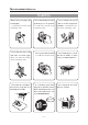
The instructions before use WARNING Ensure the power plug is Inserted tightly or it will cause electric shock overheating or fire. Never turn off the power sup- Never damage the power ply in the process of operation cable or use the non-particu- or it will cause electric shock lar kinds. or it will cause elec- overheating or fire. tric shock overheating or fire.
Don’t use fuse with differ- Never climb air conditioner ent capacity. Turn off the power supply when cleaning the air use iron to replace fuse will conditioner,otherwise,it’ll cause malfunction or fire. cause electric shock or do harm to you. Wire Never pull out the power plug Never let the air conditioner Chemical Spray should be by pulling the power cable.
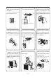
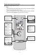
Name and funciton of each part Indoor unit Big/small air intake grill louver liquid crystral displayer Power plug drainage hose front grille remote controller Outdoor unit big handle Air in Air in -- 3 --
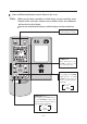
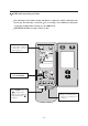
Remote control operation procedure Name and Function-Remote control Note: Be sure that there are no obstructions between reciever and remote controller. Don’t drop or throw the remote control. Don’t let any liquid in the remote controller and put the remote controller directly under the sunlight or any place where is very hot. FAN button Presse this button to change the fan speed of: SWING button When it is pressed, the louvers start to rotate automatically and stop when repressed. AUTO FAN TEMP.
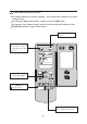
Name and Function-Remote control .(Remove the cover) Note: This type of remote controller is a kind of new current controller. some buttons of the controller which are not available to this Air conditioner will not be described below. Operate on unmentioned buttons would not impact on the normal use. Liquid crystal displayer It shows all set contents. SLEEP button Press this button to set SLEEP operation.
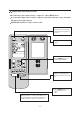
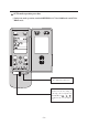
COOL mode operation procedure According to difference between room temp., and set temp. microcomputer can control cooling on or not. If room temp. is higher than set temp. , compressor runs at COOL mode. If room temp. is lower than set temp., compressor stops and only indoor fan motor runs. SET TEMP. should be in range of 16oC to 30oC. 4. Press FAN button, set fan speed. 3. Press SWING button, the louvers start to rotate automatically, and stop when repress. 5. Press TEMP. button, set suitable SET TEMP.
HEAT mode operation procedure If room temp. is lower than set temp. , compressor runs at HEAT mode. If room temp. is higher than set temp., compressor and outdoor fan motor stop, only indoor fan motor runs a while and stop. SET TEMP. should be in range of 16oC to 30oC. 3.Press SWING button, the louvers start to rotate automatically, and stop when repress it. 4.Press FAN button, set fan speed. 5.Press TEMP. button, set suitable SET TEMP. 1.Plug in, press 1/0 button, then air conditioner is turned on.
DRY mode operation procedure If room temp. is lower than set temp. much more, compressor outdoor and indoor fan motor stop. If room temp. is between 2oC of set temp., Air conditioner is drying. If room temp. is higher than set temp., it’s at COOL mode. SET TEMP. should be in range of 16oC to 30oC. 3. Press SWING button, the louvers start to rotate automatically, and stop when repress it. 4. Press TEMP. button, set suitable SET TEMP. 1/0 2. Press MODE button, set operation mode.
AUTO mode operation procedure Under Auto mode operation, standard SET TEMP. is 25oC for COOL mode and 20oC for HEAT mode . 1/0 1. Plug in, Press 1/0 button, then air conditioner is turned on. 2. Press MODE button, set AUTO operation mode.According to room temp., microcomputer can automatically set operation mode, so as for best effect.
TIMER mode operation procedure TIMER ON button At stopping, press TIME ON button, set ON TIME in range of 0 to 24 hour to start the unit automatially. 0 24h 1/0 cancel TIMER TIMER OFF button. At operating, press TIME OFF button. set OFF TIME in range of 0 to 24 hour to stop the unit automatically.
SLEEP mode operation procedure As the unit is cooling or drying, if SLEEP operation is set, SET TEMP. would increase 1oC in 1 hour and 2oC in 2 hours. As the unit is heating, if SLEEP operation is set, SET TEMP. would decrease 1oC in 1 hour and 2oC in 2 hours. 4. Press FAN button, set fan speed. 3. Press SWING button, the louvers start to rotate automatically, and stop when repress. 6. SLEEP button Press it to set SLEEP operation. 5. Press TEMP. button, set suitable SET TEMP. 2.
How to insert batteries 1. Remove the cover from the back of the remote control. 2. Insert the two batteries (Two AAA dry - cell batteries) and press button “ACL”. 3. Re - attach the cover. NOTE: Don’t confuse the new and worn or different batteries. Remove batteries when not in use for a long time. 2 Insert the 7# batteries 1 Remove the cover. 3 Re - attach the cover.
The optimum usage In order to save electricity,use it Conveniently and safely Set an appropriate room temparatrue,overcold is harmful to health Be sure to turn off the power socket when do not use in a long time. Clean the air filter and change a new one or apply to sunlight reqularly. Please take out the batteries when do not use in a long time. Avoid direct sunright, and leakage of cold air.
USER NOTICES Select the most appropriate temperature. It can avoid the electricity wasting. The airflow direction can be adjusted appropriately. The louvers can be adjusted downward at heating operation, and upward at cooling operation. Don’t leave windows and doors open while the air conditioner is on for a longtime. It can decrease the air conditioning capacity. Don’t blow the wind to animals and plants directly. It can cause a bad influence to them.
Care and Maintance Replacement of Air cleaner fastener of leftside grill faster of rightside grill button Central front panel hook (to avoid falling down of the grill) small air intake grill (rear) big air intake grill (front) 1 Remove the air intake grill Remove the big air intake grill (front) Remove the small air intake grill (rear) Stop the units, and turn off the power plug, Press it as following, drawing the grill outside then it can slip from the body.
2 Clean the air intake grill. Notices: Don’t clean the surface with brush to avoid the damage of surface. If the grill is too dirty, you can wash it with mild detergent. Don’t dry it under direct sunlight or heater, or it will cause decoloration and deformation of grill. 3 Assemble air intake grill (hook is used to avoid falling down of grill, so it is necessary) Assemble the small air intake grill (rear) Assemble big air intake grill Hang the hooks on the piping hole of small air intake grill.
Attention Stop operation and turn off the power,or the high-speed moter may cause damage to people. It doesn’t need too much strength,making this manual as reference,or it will damage to internal parts. Cleaning the air filter 1 Stop operation and turn off the power plug. 2 Disassemble the front big air intake grill Pressing the location as following,draw the big airintake grill,making it fall down of the body.
Installation and rechange of air cleaner The air cleaner combined with a low-temperature asepsis accelerant (white-green) and an active carbon(black). The former can deodorize and kill the bacillus of the air. The latter can adsorb the atom of air, enhancing the quality of air in the room. If the air-cleaner is dirty, you can wash it with water and dry it by nature. Normally clean it once half a year. If Air-cleaner use for a longtime, the efficiency will be decreased.
Troubleshooting Check the following points before requesting on service center of MUNDOCLIMA if the malfunction persist, it saves your time and money. Phenomenon Please waiting Trouble Shooting Indoor unit does not operate immediately when the air conditioner is restarted. Once the air conditioner is stopped, it will not operate in approximately 3 minutes to protect itself. There’s unusual smell blowing from the outlet after operation is started.
Immediately stop all operations and plug out, contact with service center of in following situations. Unusual noise can be heard during operation. Power fuse or switch often breaks. Carelessly splash water or something into air conditioner. Electrical lines and power plug are very hot. Wind blowing from the outlet smells terrible during operation.
Technical parameter MODEL MUR-12C MUR-12H Function Cooling Heat pump type Assistant function collocated with air-cleaner Cooling capacity (W) 3500 3500 Heating capacity (W) – 4000 Rated voltage ~220V Rated frequency 50Hz Rated current (A) 5.9/– 6.0/6.25 Maximum input current (A) 6.9 7.0 Rated power (W) 1280/– 1300/1320 Maximum input power (W) 1480 1500 480 3 Air circulation (m /h) Refrigerant and its weight (Kg) Water proof level R22 0.85 R22 1.
Accessories and Installation diagram Accessories (Check that all accessory parts are present before installation) No. Part name Diagram Qty Specification Memo 1 Wall-mounting frame 2 2 Wireless remote contrller 1 3 Battery 2 4 Power connection cable 1 5 Signal control cable 1 6 Wall-mounting frame 1 7 Tapping screw 10 ST4.
Installation dimension diagram Important Notice 1. The unit should be installed by professionals under the quidance of this manual, ensuring the normal use of it. 2. Please contact with local service center before installation, the malfunction in the process of it. caused by no specific center may be diffiaut to deal with. 3. Remove the unit should under the guidance of the professionals.
Location of installation Indoor unit 1. The inlet and outlet should not be covered so that the outflow air can reach all parts of the room. 2. Install in a location where it is easy to connect to the outdoor unit. 3. A location from which the condensation water can be drained out conveniently. 4. Avoid a location where there is heat source, high humidity or inflammable gas. 5. Install in a location where it is strong enough to withstand the full weight and vibration of the unit. 6.
Install the indoor unit Install the rear panel (unit:mm) Upper wall mounting frame Ripht wall mounting frame R72 5 Left wall mounting frame Outlet of indoor unit Rightside wallmounting frame Leftside wallmounting frame Space to certring Space to ceiling Outlet of Outlet of indoor unit indoor unit Space to wall Piping hoel Piping hoel The installation of wall mainting frame 1. Install the wall mountly frame in turn, then use gradienter to test whther they are horizontal or not. 2.
Installation of piping 1. After installation of the wall mounting frame, to locate a declining pipeing hole. 2. Choose the suitable way for piping and stretch the pipe and wire. 3. Ensure to fix a piping-hole sleeve in order to protect piping and cable escape from damage while go through the wall. Installation of right piping(rear) Installation of left piping(rear) Connection pipe (Singal wire) tubing drain hose Assemble of upper tube Assemble of downside tube.
The installation of indoor unit 1.first take off the air filter and the upper cover of electrical box before installation. 2.Hold the big handle then place indoor units on the hook of wall mountaing frame. Notice: Avoid the damage caused by the air conditioner collapse into the wall. Don’t clamp the louver 3.Move the air-conditioner in all directions, ensure they are held tightly. 4.Fix the two position with screw as picture B shows. 5.The installation height of indoor unit must be more than 2 meters high.
Electric connection 1. Take down the upper corer and wring cover of electrical box. 2. For KF(R)-28GJW/A300 KF(R)-35GJW/A300,KF(R)-40GJW/A300, first connect the blue wire of the power connection cable to the terminal “N(1)”, the brown one to “2”,the red one to 3(for KF(R)-40GJW/A300), the yellow-green one (earthing wire) connect to “ ”, as shown in figture A and Figture b. 3.Reassemble the wiring cable and upper cover of electrical box, wiring the wiring clamp to clasp the connection wire.
hole The installation of grill frame 1.Insert the hook of leftside grill into piping hole of indoor unit and hook of wall mounting frame.then fixed it with screws. 2.Insert the hook of right framework of grill hook and hole of indoor units, then fix it with screw * To installation of below pipe, fix use pincers or cutter to open holes in the obligation groove, then level off the cut with knife and fix a protection pipe for drain hose.
Install the outdoor unit Torqne wrench Installation of connect pipe 1.Align the center of piping with the correspond valve. 2.Screw in the plane nut by hand and then tighten the nut with spanner Spanner and torgue wrench refer as follows. Tightening torque(N.m) Hexangular nut 6 15~20 9.5 31~35 12 50~55 tie in plane nut Warning: Biggish torque can destroied nut Connection of cable 1.remove the big handle. 2.
The diagrams of unit wiring Power conncction cable Power conncction cable Singal cable The diagrams of unit wiring Power conncction cable Power conncction cable Singal cable Notice: Some mistakes in wiring will cause malfunction of some electrical parts. After the installation of cable, ensuring there is space between connection place and fixed place.
Leakage test screndriver 1. Take down the nut cover of turn off valve in the outdoor unit. 2. Face the central of tubing, tightering the pyramiclal nut with hand. 3. Tighten the pyramidal nut with spanner. 4. Take down the unilateralism nut of liquid ralve and gas valve. 5. Loose the core of liquid valve and check valve by hexangular panner and screwobiver respectively, discharging some gas from the latter. 6.After fifteen seconds of discharging, the refrigerant gas appears.
Test and Check Trial-operation 1. Peparation for trial-operation. (1) Don’t turn off the power before completion of all installation work. (2) The control circuitny must be conect correctly tiphtening all the electrical wire. (3) The cut-off valve of big or small pipe should loosen. (4) All the oddments especially the regulus and thrum should be cleared away from the unit. (5) Open the upper cover of panel and controller box, enswring the switch is npper cover of controller box in the “RUN” mode. 2.
Contact Instructions The name and function of each part The usage of remote controller Use and maintenance The name of each button and its function The name of each button and its function (open the cover) Cooling mode procedure Heating mode procedure Drying mode procedure Automatic operation mode procedure Timer operation mode procedure Sleep operation mode procedure Replace the batteries of the remote controller Optimum usage User notices Care and Maintance Troubleshooting Installation Service Techn