WIT2410NF 2.4GHz Spread Spectrum Wireless Industrial Transceiver Integration Guide 3079 Premiere Pkwy Ste 140 Duluth, Georgia 30097 www.Murata.
Important Regulatory Information Murata Electronics Product FCC ID: HSW-2410NF IC 4492A-2410NF Note: This unit has been tested and found to comply with the limits for a Class B digital device, pursuant to part 15 of the FCC Rules. These limits are designed to provide reasonable protection against harmful interference when the equipment is operated in a commercial environment.
Declaration of Conformity Warning! The RLAN transceiver within this device uses a band of frequencies that are not completely harmonized within the European Community. Before using, please read the European Operation Section of the Products User’s Guide for limitations. 0889 is the identification number of RADIO FREQUENCY INVESTIGATION LTD - Ewhurst Park, Ramsdell RG26 5RQ Basingstoke, United Kingdom – the Notified Body having performed part or all of the conformity assessment on the product.
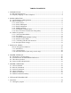
TABLE OF CONTENTS 1. INTRODUCTION ......................................................................................................................1 1.1. Why Spread Spectrum? ........................................................................................................1 1.2. Frequency Hopping vs. Direct Sequence ..............................................................................2 2. RADIO OPERATION ....................................................................................
7.2. 7.3. 7.4. 7.5. Function Keys ....................................................................................................................39 WinCom Tools ...................................................................................................................40 Script Commands ...............................................................................................................42 Demonstration Procedure .........................................................................
WIT2410 1. INTRODUCTION The WIT2410 radio transceiver provides reliable wireless connectivity for either point-to-point or multipoint applications. Frequency hopping spread spectrum technology ensures maximum resistance to noise and multipath fading and robustness in the presence of interfering signals, while operation in the 2.4GHz ISM band allows license-free use and worldwide compliance. A simple serial interface supports asynchronous data up to 230400 bps.
WIT2410 fade can be described as a frequency-selective notch that shifts in location and intensity over time as reflections change due to motion of the radio or objects within its range. At any given time, multipath fades will typically occupy 1% - 2% of the 2.4 GHz band. This means that from a probabilistic viewpoint, a conventional radio system faces a 1% - 2% chance of signal impairment at any given time due to multipath.
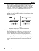
WIT2410 Figure 2 Forms of spread spectrum One disadvantage of direct sequence systems is that due to spectrum constraints and the design difficulties of broadband receivers, they generally employ only a minimal amount of spreading (typically no more than the minimum required by the regulating agencies). For this reason, the ability of DS systems to overcome fading and in-band jammers is relatively weak.
WIT2410 As an additional benefit, RF spectrum has been set aside at 2.4 GHz in most countries (including the U.S.) for the purpose of allowing compliant spread spectrum systems to operate freely without the requirement of a site license. This regulatory convenience alone has been a large motivation for the industry-wide move toward spread spectrum.
WIT2410 2. RADIO OPERATION 2.1. Synchronization and Registration As discussed above, frequency hopping radios periodically change the frequency at which they transmit. In order for the other radios in the network to receive the transmission, they must be listening to the frequency over which the current transmission is being sent. To do this, all the radios in the net must be synchronized and must be set to the same hopping pattern.
WIT2410 size parameter. The maximum amount of data sent by a base station per hop is 208 bytes. If there is no data to be sent, the base station will not transmit until the next frequency. The operation for remotes is similar to the base station without the synchronizing signal. The amount of data a remote can send on one hop is dependent upon the hop duration, the base slot size and the number of registered remotes.
WIT2410 also be set, which force the remote to wait until a certain amount of data is available or the specified delay is exceeded before transmitting. If the remote has more data than can be sent on one hop, it will send as much data as possible as a packet, adding its own address, a packet sequence number and 24-bit CRC. These additional bytes are transparent to the user application if the protocol mode is 00 (which is the default).
WIT2410 When a remote links to a base and requests registration, it requests by default that it be assigned handle 30H. This default request can be changed by the Set Default Handle command. If that handle is not currently in use by another remote, the base will assign that handle to the remote. If the requested handle is already in use by another remote, the base will assign the next higher handle that is available.
WIT2410 When setting up a network, keep in mind that time slot length, maximum packet size and hop duration are all interrelated. The hop duration parameter will determine the time slot size and the maximum amount of data that can be transmitted per hop by the remotes. There is a hard limit of the absolute maximum amount of data that can be sent on any given hop of 212 bytes regardless of any parameters. (Note that this is different than the 208 byte maximum for the base station.
WIT2410 the radio system and then query the maximum data length from one of the remotes in control mode to discover its exact setting. Divide this number by the hop duration as above to get the remote's exact capacity. 2.2.5. Full Duplex Communication From an application perspective, the WIT2410 communicates in full duplex. That is, both the user application and the remote terminal can be transmitting data without waiting for the other to finish.
WIT2410 responsibility of the user application. Refer to the Protocol Commands section for complete details. 2.3. Modes of Operation 2.3.1. Control and Data Modes The WIT2410 has two modes of operation: Control mode and Data mode. When in Control Mode, the various radio and modem parameters can be modified. When in Data Mode, only data can be transmitted. The default mode is Data Mode. There are two ways to enter Control Mode. The first way is to assert the Configure (CFG) pin on the modem.
WIT2410 2.3.3. Low Power Mode and Duty Cycling To conserve power, WIT2410 remotes power down the receiver and transmitter between hops when not in use. Base stations must remain active all the time to handle any transmission from any remote. Remotes can save even more power by enabling the duty cycle feature. This feature causes a remote to power down for 2N frequency hops where 1/2N is the duty cycle.
WIT2410 2.3.5. Co-Existing with 802.11b Networks In some cases, if a WIT2410-based network is located in close proximity to an 802.11b network, the WIT2410-based network can interfere with the 802.11b network. To avoid causing this interference, the WIT2410 radio supports a selection of hopping patterns that avoid the various 802.11b direct sequence channels. These limited band hopping patterns allow WIT2410-based networks to be used with 802.11b networks without impacting the performance of the 802.
WIT2410 3. PROTOCOL MODES In point-to-point applications, it is generally desired that the radios operate in a transparent mode. That is, raw unformatted data is sent from the host to the radio and is received as raw data from the receiving end. The addressing and error detection and correction are still performed by the radios, but it is transparent to the user application. To set up a point-to-point network, one radio has to be set up as a base station.
WIT2410 Protocol Modes Definitions mode 00 Transparent mode used for point-to-point networks or multipoint remotes; does not support any packet types. mode 01 This is the simplest protocol mode supporting Data packets only. This mode is not recommended for base radios. No CONNECT or DISCONNECT packets are supported and no sequence numbers are provided.
WIT2410 mode 12 This mode sends data transparently but supports protocol mode 2 during reception. mode 14 This mode sends data transparently but supports protocol mode 4 during reception. Note on Using Protocol Mode 4 An important difference between the WIT2400 and the WIT2410 is the dynamic assignment of time slots and handles in the WIT2410. The WIT2400 required that each remote be configured with a static address which distinguished one remote from another.
WIT2410 3.1. Packet Formats The byte formats for each packet type are shown in the table below. Packet fields are organized to fall on byte boundaries. In the case of bit-level fields, most-significant bits are on the left.
WIT2410 will not be sent and will be discarded. This parameter is variable and depends on the number of remotes currently registered. Handle 63 is reserved for broadcast packets from the base to all remotes. Acknowledgment requests are not supported for broadcasts. For this reason, it is a good idea to send broadcast messages several times to increase the odds of reaching all remotes. 3.1.3.
WIT2410 4. MODEM INTERFACE Electrical connection to the WIT2410 is made through a 16-pin male header on the modem module. The signals are 3.3 volt signals and form an RS-232 style asynchronous serial interface. The table below provides the connector pinout. Pin Signal Type 1 GND - 2 TXD Input 3 RXD Output 4 CFG Input Description Signal and chassis ground Transmit data. Input for serial data to be transmitted. In Control Mode also used to transmit modem commands to the modem. Receive data.
WIT2410 4.1. Interfacing to 5 Volt Systems The modem interface signals on the WIT2410 are 3.3 volt signals. To interface to 5 volt signals, the resistor divider network shown below must be placed between the 5 volt signal outputs and the WIT2410 signal inputs. The output voltage swing of the WIT2410 3.3 volt signals is sufficient to drive 5 volt logic inputs. 2200 From 5v Output To 3.3v Input 4300 4.2.
WIT2410 40kbps (Since the over the air transmission is synchronous, the 32kbps synchronous over the air rate is equivalent to 40kbps asynchronous into the radio serial port). If the base transmits continuously at a higher rate than this, unless the default settings are changed, the transmit buffer will eventually overflow. To allow a higher base throughput, either increase the base slot size or the hop duration or both. A similar analysis needs to be performed for the remote radios. Refer to Section 2.2.
WIT2410 5. MODEM COMMANDS The WIT2410 is configured and controlled through a series of commands. These commands are sent to the modem directly when the modem is in Control Mode when the modem is in Data Mode if the escape sequence is enabled. The command syntax is the same for either method, a one- or two-letter command followed by one or more parameters. The modem will respond with a two-byte message that indicates the new modem parameter value.
WIT2410 Set Data Rate Divisor Sets the serial bit rate between the modem and the host. This command takes effect immediately and will require adjusting the host serial rate to agree. Nonstandard rates may be programmed by entering a data rate divisor computed with the following formula: DIVISOR = (230400/RATE)-1 Round all non-integer values down. Set Protocol Mode Enables the base station to operate in a multipoint network.
WIT2410 5.2. Network Commands Network commands are used to set up a WIT2410 network and to set radio addressing and configuration.
WIT2410 remotes to link to any base station they can hear, acquiring whatever hop pattern is required. In this mode a remote can only change base stations once it is no longer registered with a base station. Set Lockout Key Allows further network segregation beyond the network number. This feature allows multiple co-located networks in which global roaming is enabled. In global roaming, a remote is allowed to link to any base regardless of the network number as long as the lockout key agrees.
WIT2410 Set Range Optimization (remote only) This command applies an adjustment factor to the over-the-air timing of remotes to compensate for the effects of propagation delay at long ranges. The default setting of 00H is suitable for ranges of 0 to 0.8 miles (1287 m), with optimal performance at 0.1 miles (162m). Each increment of this parameter adds 0.1 miles (162 m) to the working range. Thus the optimal and max ranges are determined by: optimal = 0.1mi + 0.1mi x dx = 0.17km + 0.17km x dx max = 0.
WIT2410 5.3. Protocol Commands These commands can be used to tune the transceiver for optimum transmission of data across the RF link. For most applications, the default values are adequate. Command pe[?|0-B] Description Set Alternative Frequency Band 0 = USA operation.
WIT2410 operation for Spain. When set to 3, sets appropriate operation for Japan. This setting should be set to 0, for FCC-compliant operation in the US (this is the default). For Canadian operation, set this parameter to 4. Additional 25 channel bands have been provided to avoid hopping through the various 802.11b channels. If the WIT2410 is to be used in close proximity to 802.11b networks, these alternative hopsets can be used to avoid interfering with the 802.11b networks.
WIT2410 of times every transmission will be sent, regardless of success or failure of a given attempt. When this parameter is set to FFH, RF flow control mode is entered for transmissions from the radio (See Section 2.3.4). This mode can be entered for one or both radios in a point-to-point system. When used in a point-to-point system the wu parameter should be set to 1.
WIT2410 5.4. Status Commands These commands deal with general interface aspects of the operation of the WIT2410. Command Description zb[?|0|1] Banner Display Disable 0 = disabled 1 = enabled (default) zc[?|0..2] Set Escape Sequence Mode 0 = disabled 1 = once after reset (default) 2 = unlimited times zh? Read factory serial number high byte. zm? Read factory serial number middle byte. zl? Read factory serial number low byte.
WIT2410 consumption will be roughly ¼ the consumption as when N=0. This parameter must be set to the appropriate value when more than 16 remotes are in use. Enable Low Power Acquisition Mode. When a remote is searching for a base to acquire and register with, it scans the frequency band very rapidly. This mode consumes about 80mA of current during this mode. To reduce the frequency consumption when a remote is in acquisition mode, a low power acquisition mode is provided.
WIT2410 5.6. Modem Command Summary Serial Commands sd[?|00..ff] sp[?|00..14] Set Data Rate Divisor Set Protocol Mode Network Commands wb[?|0|1] wd[?|1..3f] wl[?|0..ff] wn[?|00..3f] wg[?|0|1] wp[?|0|1] wr? wu[?|0|1] dx[?|0..62] Set Transceiver Mode Set Default Handle Set Lockout Key Set Hopping Pattern Enable Global Network Modes Set Transmit Power Read Receive Signal Strength Set Point-to-Point Direct Mode Set Range Optimization (remote only) (base only) Protocol Commands pe[?|0..4] ph[?|00..
WIT2410 6. WIT2410 DEVELOPER’S KIT The WIT2410 Developer’s Kit contains two self-contained wireless modems (HN-510s) built around the WIT2410M OEM module. In addition, two WIT2410M OEM modules are included in the kit. The self-contained units allow developers to get up and running quickly using standard RS-232 interfaces without having to build a CMOS level serial interface. In addition, the self-contained modems include status LEDs to provide modem status information visually.
WIT2410 7. WinCOM Provided with the developer’s kit is a configuration program designed especially for Murata’s wireless industrial transceivers or WIT radios. WinCOM is located on the Manuals and Software CD included in the developer’s kit. Install WinCOM by navigating to the Software Tools directory on the Manuals and Software CD and doubleclick on wincom2.1.exe follow the installation wizard. Once it has installed, open WinCOM by double-clicking on the WinCOM icon on the desktop.
WIT2410 WinCom’s menu structure is typical of Windows conventions with File, Edit, Options, Tools and Help selections. Under File, Save Settings (Ctrl S) saves the current WinCom settings to the hard drive, Print (Ctrl P) sends whatever text is in the display field to the printer and Exit terminates the program. Under Edit, Copy, Paste, Find (search) and Select All perform the familiar Windows functionality in typical fashion.
WIT2410 7.1. Starting the program When started, WinCOM de-asserts and re-asserts the DTR line to the radio which resets the radio causing the sign-on banner to be displayed. If the baud rate on the computer doesn’t match the baud rate of the radio, illegible characters will be displayed. By hitting the PgUp or PgDn key to change the baud rate, then pressing F1 twice to toggle DTR (resets the radio) and causes a new banner to be displayed.
WIT2410 To change configuration parameters, the radio must be put into configuration mode by clicking on the Config Mode button on the WinCOM window immediately after opening WinCOM or after cycling power to the radio. Another method is to toggle the DTR by pressing the F1 key twice, which de-asserts then re-asserts DTR, then pressing the F3 key (or Config Mode button). When the radio is in configuration mode, a “>” prompt character is displayed in the WinCom window as shown above.
WIT2410 If the other radio is sending data, the received data will be displayed in the WinCOM window. If the Binary box is checked, all characters received will be displayed subject to the limitations of Windows. For example, a carriage return will not return the cursor to the left side of the window but the character corresponding to 0xd value of the carriage return will be displayed. Similarly, if the Hex Mode box is checked, all characters are displayed in hexadecimal format.
WIT2410 After naming the file and clicking on OK, the Capture Data window opens and shows the amount of data being received. Clicking on Done stops the loading of received data into the file. 7.2. Function Keys All of the function key shortcuts are described below: F1 Toggles state of DTR (Sleep). State is shown in status line. F2 Toggles state of RTS. State is shown in status line. F3 Transmits “:wit2400”. Used to enter control mode. F5 Toggles local echo.
WIT2410 7.3. WinCom Tools There are seven selections under the Tools menu. The first, Obey CTS is useful when just a three wire connection is made between the radio and the computer. Some PCs let the CTS input line float. If CTS is not asserted, the PC COM port will not send data. Note: Unchecking this selection will have the PC COM port ignore the state of CTS and transmit data. When WinCOM’s transmit mode is used, data is sent continuously until the user stops it by clicking on Stop or pressing F6.
WIT2410 The Packet Builder is an easy way to test the multipoint addressing mode of the WIT241x radio. Since the WIT241x operates in a star configuration in multipoint mode, only the base radio needs to address data to specific remotes. All remotes send data back to the base and do not need to address the data to the base. To send a packet of data to a specific remote in a multipoint network, enter the handle of the desired remote in the Handle window.
WIT2410 7.4.
WIT2410 The seventh tool allows the loading of a data file for transmission. Navigate to a file then click Open and the file is transmitted immediately. The Capture File dialog displays with a bar showing loading progression. Once the file has finished transmitting, the Final Average Throughput and Bytes sent numbers will be displayed. Finally, the eighth tool is Save to File which launches a Save As dialog that allows any data received to be loaded into a file.
WIT2410 7.5. Demonstration Procedure The procedure below provides a quick demonstration of the WIT241x. 1. Attach a transceiver to each computer, preferably between 5' and 30' apart for convenience. 2. Start WinCOM running on both computers If you prefer, almost any other serial communications program such as Procomm or QModem set for 9600 bps will also work. 3.
WIT2410 8. Troubleshooting Radio is not responding. Make sure DTR is asserted to bring the radio out of sleep mode. DSR should be on to indicate the radio is ready. Can’t enter modem control mode. Make sure the host data rate is correct. The WIT2410 defaults to 9600 bps asynchronous. Evaluation units do not have external access to the CFG_SEL signal; you must use the :wit2410 power-on escape sequence to access modem control mode.
WIT2410 This indicates that the transmitter is unable to reliably get its data across. This may be the result of an interfering signal, but most often is caused by overloading of the network. Adjusting the protocol parameters may increase the network efficiency. Receiving terminal drops characters periodically. Set the number of retries to a high number and send a few characters. Check that the transmitted data can get through under these conditions.
WIT2410 9. APPENDICES 9.1. Technical Specifications 9.1.1 Ordering Information WIT2410M4 OEM Module, Serial connector pins down - Standard WIT2410S4 OEM Module, Serial connector pins up 9.1.2. Power Specifications Vcc Input Range: Operating Temperature Range: 3.3v to 10.0v -30C to +70C Current Consumption (Max transmit power, 230.4Kbps I/O) Mode Sleep Standby Typical Average Peak (Tx) Remote 50µA 20mA 50mA 80mA Base Station N/A N/A 80mA 100mA 9.1.3.
WIT2410 9.2. Serial Connector Pinouts Signal GND TXD RXD CFG RTS SLEEP DCD CTS HN-510 DB9 Pinout 5 3 2 7 4 1 8 WIT2410M/S4 OEM Pinout 1 2 3 4 5 6 7 8 Note: The WIT2410M4 is the standard part number and has the serial connector pins pointing down allowing connection to a mother board without using a cable. WIT2410S4 has the serial connector pins pointing up. The HN-510 is wired as a DCE device and as such can be connected to DTE devices such as PCs with a straight-through cable.
WIT2410 9.4. Technical Support For technical support call Murata at (678) 684-2000 between the hours of 8:30AM and 5:30PM Eastern Time.
WIT2410 9.5. Reference Design 1 Optional pullups to keep RTS and DTR asserted when left unconnected D1 MBR0520L V1 1 C3 1 uF C5 0.1uF 4 C2+ C4 1 uF + 3 8 9 11 TXD DTR RTS RS232 Interface + C1- 2 2 2 25 C2 1 uF 27 1 1 R2 6.8k V+ + 1 C1 0.22uF C1+ 26 2 2 V CC 28 R1 6.8k V CC 3.3V U5 12 10 7 6 5 RXD DCD CTS 16 C2R1IN R2IN R3IN T5OUT T4OUT T3OUT T2OUT T1OUT R1OUT R2OUT R3OUT T5IN T4IN T3IN T2IN T1IN 21 20 18 17 19 22 23 24 TXD_3.3V DTR_SLEEP_3.3V RTS_3.3V RXD_3.3 V DCD_3.
WIT2410 9.6.1.
WIT2410 9.6.2.
WIT2410 10. Warranty Seller warrants solely to Buyer that the goods delivered hereunder shall be free from defects in materials and workmanship, when given normal, proper and intended usage, for twelve (12) months from the date of delivery to Buyer. Seller agrees to repair or replace at its option and without cost to Buyer all defective goods sold hereunder, provided that Buyer has given Seller written notice of such warranty claim within such warranty period.