Certification Exhibit FCC ID: HSW-CCT24 IC: 4492A-CCT24 FCC Rule Part: 15.247 IC Radio Standards Specification: RSS-210 ACS Project Number: 14-0204 Manufacturer: RF Monolithics Model: CCT24 Manual 5015 B.U.
CCT24 Series 2.
Important Regulatory Information RFM Product FCC ID: HSW-CCT24 IC: 4492A-CCT24 NOTE: This equipment has been tested and found to comply with the limits for a Class A digital device, pursuant to part 15 of the FCC rules. These limits are designed to provide reasonable protection against harmful interference when the equipment is operated in a commercial environment.
Table of Contents 1.0 Introduction ...................................................................................................................................... 5 1.1 Why Spread Spectrum?................................................................................................................ 5 1.2 Frequency Hopping versus Direct Sequence ............................................................................... 6 2.0 CCT24 Radio Operation.................................................
4.0 4.1 4.1.1 4.1.2 4.1.3 4.1.4 4.1.5 4.1.6 4.2 4.2.1 4.2.2 4.2.3 4.2.4 4.2.5 4.2.6 4.2.7 4.2.8 4.2.9 4.2.10 4.2.11 4.2.12 4.2.13 4.2.14 5.0 5.1 5.2 5.3 5.4 5.5 5.6 5.6.1 5.6.2 5.7 5.8 6.0 7.0 7.1 8.0 8.1 8.2 9.0 Protocol Messages......................................................................................................................... 40 Protocol Message Formats......................................................................................................... 40 Message Types .........
1.0 Introduction The CCT24 series transceivers provide highly reliable wireless connectivity for point-to-point, point-tomultipoint, peer-to-peer or tree-routing applications. Frequency hopping spread spectrum (FHSS) technology ensures maximum resistance to multipath fading and robustness in the presence of interfering signals, while operation in the 2.4 GHz ISM band allows license-free use world wide. The CCT24 supports all standard serial data rates for host communications from 1.2 to 460.
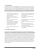
Narrow-band versus spread-spectrum transmission Figure 1.1.1 1.2 Frequency Hopping versus Direct Sequence The two primary approaches to spread spectrum are direct sequence spread spectrum (DSSS) and frequency hopping spread spectrum (FHSS), either of which can generally be adapted to a given application. Direct sequence spread spectrum is produced by multiplying the transmitted data stream by a much faster, noise-like repeating pattern.
One disadvantage of direct sequence systems is that due to design issues related to broadband transmitters and receivers, they generally employ only a minimal amount of spreading, often no more than the minimum required by the regulating agencies. For this reason, the ability of DSSS systems to overcome fading and in-band jammers is relatively weak.
configured to send join announcements to a host application for an unlimited number of radios. The application can then verify the continued presence of each radio in the network through periodic polling. The CCT24 also supports a RemoteLeave command that allows a host application to release a radio from the network. This is useful to remove any rogue radios that may have joined then network when authentication is not being used.
radio, protocol formatting must be used unless the data being sent includes addressing information that the devices connected to the remotes/routers can use to determine the intended destination of the broadcast data. Protocol formatting is also required for configuration commands and responses, and sensor I/O commands and responses. Protocol mode can be used at the base while transparent mode is used at the remotes.
BaseSlotSize parameters and the number of registered radios. The MinPacketLength and TxTimeout parameters operate in a remote in the same manner as in the base. 2.6 RF Transmission Error Control The CCT24 supports two error control modes: automatic transmission repeats (ARQ), and redundant transmissions for broadcast packets. In both modes, the radio will detect and discard any duplicates of messages it receives so that the host application will only receive one copy of a given message.
packet sequence number and error checking bytes to the data when it is transmitted. These additional bytes are not output at the remote in transparent mode. The sequence number is used in acknowledging successful transmissions and in retransmitting corrupted transmissions. A two-byte CRC and a one-byte checksum allow a received transmission to be checked for errors. When a transmission is received by the remote, it will be acknowledged if it checks error free.
2.8.4 Tree-Routing Operation A CCT24 tree-routing system consists of a base, remotes and up to 63 routers. A router is basically a remote that has been configured with two operating modes - a base mode for its “child” radios and a remote mode for its “parent” router or the system base. This allows a router to do tree-routing in addition to normal remote functions. Each router can forward messages to/from a total of 126 child radios.
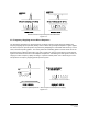
Figure 2.10.1 2.10.1 Polling Mode Polling channel access is used for point-to-point and point-to-multipoint systems where only one remote will attempt to transmit data at a time, usually in response to a command from the base. Polling (mode 0) is a special case of CSMA mode 1. The user can set the BaseSlotSize and CSMA_ RemtSlotSize parameters when using this mode. Since only one remote will attempt to transmit at a time, to minimize latency, the CSMA_Predelay and CSMA_Backoff parameters are not used.
the channel busy a second time, the amount of time the radio will wait before checking the channel will increase. It will continue to increase each subsequent time the channel is busy until the channel is finally found idle. This is the classic CSMA technique that handles the situation where a number of radios hold data to send at the same time. The CSMA_ Predelay parameter controls the maximum time that a radio will wait before first listening to see if the channel is clear for a transmission.
immediately as remotes join or leave the network. When running in protocol mode on a remote, care must be taken not to generate messages too long to be sent in a single hop due to automatic RemoteSlotSize reduction. TDMA Fixed Slots (mode 3) is used for applications that have fixed data throughput requirements, such as isochronous voice or streaming telemetry. The slot start time and the RemoteSlotSize are computed automatically by the CCT24 network in this mode.
before transmitting it. If the message is not completely received by the time the base transmits, the base will wait until the next hop to transmit the message. The throughput for each remote is: RemoteSlotSize/HopDuration In a TDMA mode, the RemoteSlotSize is set automatically based on the number of remotes and the BaseSlotSize. Note that the base radio always reserves BaseSlotSize amount of time in each hop whether or not the base has user data to send.
It is often desirable to limit the amount of data a CSMA remote can send in one transmission. This prevents one remote from hogging network throughput. To accommodate this, the CCT24 provides a CSMA_RemtSlotSize parameter that is user configurable. When a remote has transmitted CSMA_ RemtSlotSize bytes on a given hop, it will stop transmitting until the next hop.
The other factor impacting latency is retries. This impact is not unique to frequency hopping radios but is common among all wireless technologies. A radio only transmits data once per hop. It needs to wait until the next hop to see if the transmission was received at the destination. If not, the radio will transmit the data again and wait for the acknowledgement. This can happen up to ARQAttemptLimit number of times which is equal to ARQAttemptLimit times HopDuration amount of time. 2.11.
data rate, hop duration, base slot size and maximum number of remotes. Although the remote slot size and remote slot time allocation are automatically set in mode 2, the user must predetermine these values to assure a valid operating configuration. First, set the BaseSlotSize to accommodate the maximum number of data bytes in a base transmission. Next, determine the RemoteSlotSize required to accommodate the maximum number of data bytes in a remote transmission.
2.12 Tree-Routing Systems As discussed in Section 2.8.4, CCT24 tree-routing systems can cover much larger areas than other CCT24 networks, with the trade-off that tree-routing increases message transmission latency. Treerouting systems are well suited to many industrial, commercial and agricultural applications. Compared to other CCT24 network configurations, however, tree-routing systems require somewhat more initial planning and commissioning steps, as discussed in this Section. 2.12.
Data sent from the base radio in the central location will be routed down the “tree” to the intended node of the network. Data from the nodes will be routed up the tree to the base or to another node in the system. Note that it is possible to send data from one node to another node rather than sending it to the base.
2.12.2 Tree-Routing System Networks A CCT24 tree-routing system consists of one base and up to 63 routers, where the base and each router 1 can forward messages to/from a total of 126 child radios (leases enabled) . A child radio can be either a remote or router, within the system limitation of 63 routers total. Within a CCT24 tree-routing system, a network refers to a group of radios communicating with a router or base acting as a parent, and all of the child radios that are linked to this parent.
The InitialParentNwkID parameter controls which parent a child router or remote can join. Setting this value to 0x00 forces a router or a remote to join with only the base. Setting this parameter to the NwkID of a parent router forces a child router or a remote to join only this parent’s network. Setting this parameter to 0xFF in a router or remote allows them to join with any parent. The StaticNetAddr parameter controls the assignment of the NwkAddr byte in a remote’s system address.
development by removing the need to dynamically update a database that matches system addresses to MAC addresses for each router and remote. The task of manually assigning system addresses to all routers and remotes in a tree-routing system can be somewhat tedious. Contact RFM’s module technical support group for the latest support tools for manual address assignment. Table 2.12.4.1 summarizes radio parameter settings for each assignment method.
2.13 Serial Port Operation CCT24 networks are often used for wireless communication of serial data. The CCT24 supports serial baud rates from 1.2 to 460.8 kb/s. Listed in Table 2.13.1 below are the supported data rates and their related byte data rates and byte transmission times for an 8N1 serial port configuration: Baud Rate kb/s Byte Data Rate kB/s Byte Transmission Time ms 1.2 0.12 8.3333 2.4 0.24 4.1667 4.8 0.48 2.0833 9.6 0.96 1.0417 19.2 1.92 0.5208 28.8 2.88 0.3472 38.4 3.
The average full-duplex serial port byte rate that can be supported under error free conditions is: 64 Bytes/4.85 ms = 13.2 kB/s, or 132 kb/s for 8N1 Continuous full-duplex serial port data streams at a baud rate of 115.2 kb/s can be supported by this configuration, provided only occasional RF transmission errors occur. Plan on an average serial port data flow of 90% of the calculated error-free capacity for general-purpose applications.
GPIO port 4 can be alternately configured to provide a received message flag, referred to as SPI_RX_ AVL. Operation of this line is shown in Figure 2.14.3. Once the SPI_RX_AVL flag goes high, RX message bytes can be clocked out on the MISO line by clocking 0x00 null bytes and/or transmit message bytes in on the MOSI line. Note that nine to ten 0x00 null bytes will precede each received message, which is always protocol formatted.
2.15 Sleep Modes To save power in applications where a remote transmits infrequently, the CCT24 supports hardware and firmware sleep modes. Hardware sleep mode is entered by switching SLEEP/DTR Pin 11 on the CCT24 from logic low to high. While in hardware sleep mode, the CCT24 consumes less than 50 µA at room temperature. This mode allows a CCT24 to be powered off while its host device remains powered. After leaving hardware sleep mode, the radio must re-synchronize with the base and re-register.
If the remote is linking for the first time or was unsuccessful linking on its last attempt, it will remain awake to record the beacon system parameter list. At wakeup, the WakeLinkTimeout timer is started. If the remote is unable to acquire link before this elapses, it goes back to sleep.
Pin Awake Sleep /HOST_RTS Normal operation high impedance /HOST_CTS Normal operation 0V /DCD Normal operation 0V ACT 3V 0V DIVERSITY Normal operation 0V RADIO_TXD Normal operation Hi-Z RADIO_RXD Normal operation 0V Table 2.15.1 Note that the ACT pin may be used by a local host to detect when a sleeping remote is awake. The behavior of the GPIOs during sleep is governed by the GPIO_ SleepMode, GPIO_SleepDir, and GPIO_SleepState configuration registers.
co-located networks may occasionally try to transmit on the same frequency at the same time. This can slightly reduce the network throughput. Where a wide pulse can be used, it should be sent to reset all base patterns to their first frequency following the reset or power-up of any of the co-located bases. Thereafter a cycle of N -1 narrow pulses and then 1 wide pulse should be sent, where N is the number of frequencies in the subband being used.
3.0 CCT24 Hardware The major components of the CCT24 include a 2.4 GHz FHSS transceiver and a low current 32-bit microcontroller. The CCT24 operates in the 2.4 GHz ISM band. The module includes nine frequency subbands and 38 total frequency channels to support the various 2.4 GHz frequency allocations used throughout the world. The CCT24 has three selectable RF output power levels: 1, 10, and 63 mW. Also, there are four selectable RF transmission rates: 38.4, 115.2, 200 and 500 kb/s.
3.1 CCT24 Specifications Characteristic Sym Operating Frequency Range Minimum Typical 2409.55 Hop Dwell Time Maximum Units 2479.85 MHz 10 ms Number of Frequency Hopping Subbands Number of RF Channels in a Subband 38 Modulation FSK RF Data Transmission Rates 362 kb/s -95 dBm 1, 10, 63 mW 50 Ω Receiver Sensitivity: 10-5 BER @ 362 kb/s Transmitter RF Output Power Levels Optimum Antenna Impedance RF Connection U.
3.2 Module Interface Electrical connections to the CCT24 are made through the I/O pins on the CCT24. The hardware I/O functions are detailed in the table below: Pad Name I/O Description 1 PKT_DET O Packet detect output. Signal switches logic high at the end of the start-of-packet symbol and switches logic low at the end of the end-of-packet symbol on both received and transmitted packets. PKT_DET provides a timing reference for use in network timing evaluations, etc. 2 RSVD - Reserved pad.
25 ACT O Data activity output, logic high when data is being transmitted or received. 26 /DCD O Default functionality is data carrier detect output, which provides a logic low on a remote when the module is locked to FHSS hopping pattern and logic low on a base when at least one remote is connected to it. 27 RSVD - Reserved pad. Leave unconnected. 28 RSVD - Reserved pad. Leave unconnected. 29 RSVD - Reserved pad. Leave unconnected. 30 /HOST_RTS I UART flow control input.
Trace Separation from Length of Trace Run 50 ohm Microstrip Parallel to Microstrip 100 mil 125 mill 150 mil 200 mil 200 mil 290 mil 250 mil 450 mil 300 mil 650 mil Table 3.3.2 connector and the antenna or antenna connector on the host circuit board should be implemented as a 50 ohm stripline. Referring to Figure 3.3.1, the width of this stripline depends on the thickness of the circuit board between the stripline and the groundplane.
3.7 Power-On Reset Requirements When applying power to the CCT24, the /RESET Pin 39 and the RADIO_TXD Pin 31 must be initially held low. The /RESET pin must be held low until the power supply voltage reaches 3.3 volts for 100 ms, and then set high. The RADIO_TXD must be held low an additional 10 ms after the /RESET pin goes high. RADIO_TXD is weakly pulled down with a 100K ohm resistor to meet the power-on reset requirement, unless this line is driven high by an external signal. 3.
interference to other users, the antenna type and its gain should be so chosen that the equivalent isotropically radiated power (e.i.r.p.) is not more than that necessary for successful communication. Conformément à la réglementation d'Industrie Canada, le présent émetteur radio peut fonctionner avec une antenne d'un type et d'un gain maximal (ou inférieur) approuvé pour l'émetteur par Industrie Canada.
4.0 Protocol Messages 4.1 Protocol Message Formats The CCT24 is configured and controlled through a series of protocol mode messages. All protocol mode messages have a common header format: 0 SOP 1 Length 2 PktType 3… variable number of arguments … Figure 4.1.1 The scale above is in bytes. The Start-of-Packet (SOP) character, 0xFB, is used to distinguish the beginning of a message and to assure synchronization in the event of a glitch on the serial port at startup.
is used for all multi-byte arguments, where the lowest order byte is the left-most byte of the argument and the highest order byte in the right-most byte of the argument. 4.1.
for routers - 0x00 0xNN 0xFF, where NN is the NwkID of the router. for remotes - 0xMM 0xNN 0xFF, where NN is the NwkID of the parent router and MM is the network address of the remote.
Range = Range measurement of joining radio (1 byte). Each count equals 0.29 miles. BootSelect = Code indicating whether to do a normal reset or a reset to the bootloader (1 byte) (0 = normal reset, 1 = reset to bootloader) PermitStatus = Permission for new node to join, 0x00 = denied, 0x01 = permitted (1 byte) BackoffTime = Time that a node will avoid trying to join a network, in seconds (2 bytes) (0xFFFF = back off until reset or power cycled) 4.1.
The target remote will issue a DiscoverReply command as follows: 0xFB 0x08 0x16 0x00 0x02 0x01 0x00 0x01 0x01 0xFF The 0x00 Status byte value indicates a response from the remote. The tree-routing system address of the target remote is received in Little-Endian byte order, so the address is 0xFF0101. Referring to Figure 2.12.1.2, this is the system address of Remote R1. 4.2 Configuration Registers The configuration registers supported by the CCT24 are described below.
The auto setting will cause a remote to try all four over-the-air rates when scanning for a network to join. Setting the RF_DataRate to a fixed value on the remotes will allow a network to link much faster than using the auto setting. However, if the base RF_DataRate is changed when the remotes are set to a fixed rate, the network will not link. Note that changing this setting does not take effect immediately. It must be followed by a MemorySave command (See Section 4.2.9) and then a hardware reset.
WakeLinkTimeout - this parameter sets the maximum length of time that a remote in sleep mode will spend trying to acquire a link to its base before going back to sleep, from a minimum of 100 ms to 25.5 s in 100 ms units. If this value is set to 0, the remote will stay awake and continue trying to link to its base indefinitely. TxPower - this parameter sets the transmit power level used by the base (fixed), and the maximum transmit power level used by a remote.
StaticNetAddr - this parameter holds the lower byte of the system address of a remote. Assigning a value other than 0xFF provides a fixed (static) address. When this parameter is set to 0xFF, the router assigns the lower byte of the system address to a remote dynamically. When using fixed network addressing, any device that can connect to a parent that has any children with fixed network addresses must also have a unique fixed network address, including child routers.
Bank 1 holds configuration parameters to be input to the base only. The base passes these parameters to the remotes as needed. The exception is the ARQ_AttemptLimit parameter. If ARQ_Mode bit 1 is set to 1 at the base, the ARQ_AttemptLimit parameter can be set in the remotes and used. FrequencyBand - this parameter selects the frequency hopping subband. Nine subbands are available, as shown below. Note that operation in France is limited to subbands 0x04, 0x05 and 0x07.
ARQ_AttemptLimit - this sets the maximum number of attempts that will be made to send a data packet on the RF link. Setting this parameter to the maximum value of 63 is a flag value indicating that there should be no limit to the number of attempts to send each packet (infinite number of attempts). This mode is intended for point-to-point networks in serial data cable replacement applications where absolutely nopackets can be lost.
AuthMode - this parameter is valid on the base only. It controls how remotes are permitted to join the network. Permitted values are: 0 = Any remote may join 1 = Authentication by base radio permission table 2 = Authentication by request to host application 3 = Lock authentication to permit only currently registered remotes P2PReplyTimeout - This parameter sets the reply timeout for peer-to-peer packets sent from one node to another.
CurrNwkAddr - this returns the address of the radio in its parent’s network. CurrNwkID - this returns the ID of the network the radio is currently assigned to or connected to. A value of 0xFF means the radio is scanning for a network but has not yet joined one. CurrRF_DataRate - this returns the RF data rate of the network that the radio is currently assigned to or connected to. If the radio is scanning for a network, this is the current data rate it is using in the scan.
CurrAttemptLimit - this returns the value of ARQ_AttemptLimit currently in use (depending on the selected ARQ_Mode, it may not always match the local EEPROM value). CurrRangeDelay - returns the current propagation delay for this remote as measured from the base (applies to remote nodes only). FirmwareBuildDate - date of firmware build in MM/DD/YY format. FirmwareBuildTime - time of firmware build in HH:MM:SS format. ModelNumber - DNT model number parameter, 0x01 = DNT900, 0x02 = CCT24.
0x04 0x05 0x06 0x07 Even parity, 8 data bits, 1 stop bit Even parity, 8 data bits, 2 stop bits Odd parity, 8 data bits, 1 stop bit Odd parity, 8 data bits, 2 stop bits Note that 8-bit data with no parity is capable of carrying 7-bit data with parity for compatibility without loss of generality for legacy applications that may require it. SerialControls - this parameter affects the way the radio responds to the various serial control lines.
the end of each received message. Figure 4.2.4.1 shows a typical relation ship between the /SS line (red trace) and the SCLK line (blue trace). Figure 4.2.4.1 When periodic I/O reporting is enabled on a CCT24 remote configured as an SPI Master, the remote will clock out a stored command string, SPI_MasterCmdStr, to collect data from a Slave peripheral each time the I/O report timer fires. The collected data is then transmitted to the base as a TXData message.
SPI_MasterCmdLen - this parameter sets the length for the SPI Master command string that will be used to interrogate the slave peripheral, when SPI Master mode is selected with periodic I/O reporting enabled. SPI_MasterCmdStr - this parameter holds the SPI Master command string that is used to interrogate the slave peripheral when SPI Master mode is selected with periodic I/O reporting enabled. 4.2.
ProtocolSequenceEn - enables or disables the EnterProtocolMode ASCII command string to switch from transparent mode to protocol mode. Valid settings are 0 = disabled, 1 = one time at startup, 2 = enabled at any time. The default is enabled at anytime. Note that if this parameter is set to 0 and saved to memory, protocol mode can no longer be invoked through the radio’s main serial port or SPI connection.
4.2.
GpioAlt bit is set for GPIO4, the corresponding GpioSleepMode bit is ignored and GPIO4 is controlled directly by the GpioSleepState parameter bit 7. GPIO_SleepDir - when GPIO_SleepMode is enabled, this parameter functions as a secondary GPIO_Dir to set the direction of the GPIOs during a device’s sleep period. This enables the user to provide alternate configurations during sleep that will help minimize current consumption. Bits 0..5 correspond to GPIO0.. GPIO5.
IO_ReportInterval - when periodic I/O reporting is enabled, this parameter sets the interval between reports. Units are 10 ms increments, and the default report interval is every 30 seconds but can be set as long as 497 days. IO_ReportPreDel - this parameter sets the delay in milliseconds between an event trigger and the time the I/O register bank is read and sent in an EVENT report.
RegMACAddr0..25 - this bank holds the MAC addresses of all radios registered to a base or router. Up to 126 MAC addresses can be registered. Each bank parameter can hold up to five MAC addresses, with each MAC address containing three bytes are in little-Endian order. Three-byte segments in a parameter not holding a MAC address with hold a null address: 0x00 0x00 0x00. Note that unlike parameters in other banks, the bank offset used in get commands is by parameter rather than by byte.
0x0030 0x0060 0x00C0 0x0180 9.6 kb/s 4.8 kb/s 2.4 kb/s 1.2 kb/s Note that if a value of 0x0000 is specified, the maximum data rate of 460.8 kb/s will be selected. MemorySave - writing 0x00 to this location clears all registers back to factory defaults. Writing a 0x01 to this location commits the current register settings to EEPROM. Writing 0x02 to this location saves the current setting to EEPROM and forces a software reset.
4.2.14 Protocol Mode Event Message Example In this example, the IO_ReportInterval is set to 10 seconds and the periodic report timer bit in the IO_ReportTrigger parameter is set on the remote, with MAC address 0x123456. This causes event messages to be sent from this remote every 10 seconds. The IO_ReportInterval and the IO_ReportTrigger parameters are loaded using SetRemoteRegister commands.
5.0 CCT24DK Developer’s Kit Figure 5.0.1 shows the main contents of a CCT24DK Developer’s kit: Figure 5.0.1 5.1 CCT24DK Kit Contents Two CCT24 radios installed in DNT interface boards (labeled Base and Remote) Two installed U.FL coaxial jumper cables and two 2 dBi dipole antennas Two 9 V wall-plug power suppliers, 120/240 VAC, plus two 9 V batteries (not show above) Two RJ-45/DB-9F cable assemblies, one RJ-11/DB-9F cable assembly, two A/B USB cables One CCT24DK documentation and software CD 5.
5.4 Developer’s Kit Default Operating Configuration The default operating configuration of the CCT24DK developer’s kit is TDMA Mode 2, point-to-point, with transparent serial data at 9.6 kb/s, 8N1. One CCT24 is preconfigured as a base and the other as a remote. Labels on the bottom of the interface boards specify Base or Remote. The defaults can be overridden to test other operating configurations using the DNT Demo utility discussed in Section 5.5.
As shown in Figure 5.5.1, there is a jumper on pins J14. This jumper can be removed and a current meter connected across J14 to measure just the CCT24’s current consumption during operation. Figure 5.5.
There are three serial connectors on the interface boards. The RJ-45 connector provides a high-speed RS232 interface to the CCT24’s main serial port. The USB connector provides an optional interface to the radio’s main serial port. The RJ-11 connector provides a high-speed RS232 interface to the radio’s diagnostic port. The DNT Demo utility program runs on the radio’s main port. Many desktop PCs have a built-in serial port capable of operation at 9.6 kb/s. The kit can be run satisfactorily at the 9.
5.6.1 Initial Kit Operation Create a file folder on the PC and copy the contents of the kit CD into the folder. The DNT Demo utility program runs on the radio’s main port. The preferred PC interface is a serial port capable of operating at 9.6 kb/s or faster. As discussed above, the USB interface can also be used. Connect the Base to the PC and power up the Base and the Remote development boards using the wallplug power supplies. The DNT Demo utility program is located in the PC Programs folder.
Click on Connect to open the Select Comm Port Settings dialog box, as shown in Figure 5.6.1.2. Set the baud rate to 9600 (9.6 kb/s). Set the CommPort to match the serial port connected to the Base, either the hardware port or the USB virtual serial port. Then click OK to activate the serial connection. Figure 5.6.1.2 At this point the Demo will collect data from the Base, filling in data in the Local Radio column on the Demo window. The Status Window should also show that the Remote has joined the Base.
Connect PCs to both the Base and the Remote for serial communication testing. Click the Stop button under the Refresh Delay label on the I/O Tools tab and move to the Transmit Tools tab, as shown in Figure 5.6.2.1. Figure 5.6.2.1 Pressing the Transmit button on this screen sends the message in the Data to Transmit text box to the selected MAC Address. Note that the MAC address a remote uses for the base is always 0x000000. Data sent to the local radio is displayed in the Received Data text box.
Returning to the I/O Tools tab, the multi-tab Configuration window for each radio can be accessed by clicking on its Config button. The data presented on the first six tabs corresponds to configuration register Banks 0 through 5 as discussed in Section 4.2 above, with the data on the next two tabs corresponding to configuration register Bank 6, the data on the next tab corresponding to Bank 7, the data on the following two tabs corresponding to Bank 8, and the data on the last tab corresponding to Bank 9.
from the keyboard, and then pressing the Apply Changes button. Note that Bank 1 holds configuration parameters for the base only except for ARQ_Mode, which applies to both the base and the remotes. Figure 5.6.2.4 Figure 5.6.2.4 shows the Status tab contents, corresponding to Bank 2. Note the Status tab contains read-only parameters. Figure 5.6.2.5 Figure 5.6.2.5 shows the Serial tab contents corresponding to Bank 3. The values shown are the defaults for serial port operation.
Figure 5.6.2.6 Figure 5.6.2.6 shows the Protocol tab contents, corresponding to Bank 4. Transparent data serial communication is currently chosen. Figure 5.6.2.7 Figure 5.6.2.7 shows the I/O Peripherals tab contents, corresponding to Bank 5. GPIO ports 1 through 5 are logic low, GPIO port 0 is logic high. The 10-bit ADC input readings and PWM output settings are given in Big-Endian byte order. Event flags are presented on the right side of the window.
Figure 5.6.2.8 Figure 5.6.2.8 shows the first I/O Setup tab contents, corresponding to Bank 6 GPIO parameters. This tab allows the direction of the GPIO ports to be set both for active and sleep modes, and in the case of GPIO outputs, the initial power up states and sleep mode states to be set. When GPIO ports 0 - 3 are configured as inputs, event interrupts can be set for them with check boxes. The type of interrupt trigger is selected from the drop-down boxes to the right of the check boxes.
Figure 5.6.2.10 Figure 5.6.2.10 shows the Auth List tab, where the MAC addresses of the remotes authorized to join the network in AuthMode 1 are input into Bank 7. Figure 5.6.2.11 Figure 5.6.2.11 shows the first Routing Table tab, which displays part of the contents of Bank 8. This bank contains the tree-routing active router ID table, which is maintained by a base for its system. It describes the organization of all active routers in the system.
Figure 5.6.2.12 Figure 5.6.2.12 shows the second Routing Table tab, which displays the rest of the contents of Bank 8. Figure 5.6.2.13 Figure 5.6.2.13 shows the Registered tab, which displays the first seven parameters in Bank 9. This bank holds the MAC addresses of all radios registered to a base or router. Up to 126 MAC addresses can be registered. Each bank parameter can hold up to five MAC addresses, with each MAC address containing three bytes.
5.7 DNT Wizard Utility Program DNT Wizard is a complementary program to DNTDemo that emphasizes the details of serial communication between a CCT24 and its host computer. The DNT Wizard start-up window is shown in Figure 5.7.1. Figure 5.7.1 DNT Wizard uses three Function keys: F1 toggles the SLEEP/DTR input to the CCT24 on and off. This allows the CCT24 to be reset. F2 toggles the RTS input to the CCT24 on and off, providing manual flow control. F6 toggles test transmissions on and off.
Click on Connect to open the Select Comm Port Settings dialog box, as shown in Figure 5.7.2. Set the baud rate to 9600 (9.6 kb/s). Set the CommPort to match the serial port connected to the Base, either the hardware port or the USB virtual serial port. Then click OK to activate the serial connection. Figure 5.7.2 At this point the Wizard will collect data from the Base, filling in data under Current Settings as shown in Figure 5.7.3. The Status Window should also show that the Remote has joined the Base.
There are three tabs on the DNT Wizard main window: Receive Data, Transmit Data and Wincom. Figure 5.7.4 Received messages are displayed in the Receive Data tab, along with the MAC address of the sender and the RSSI (signal strength) of the received message in dBm. See Figure 5.7.4.
Figure 5.7.5 The Transmit Data tab is shown in Figure 5.7.5. The message to send is input in the Data to Transmit text box. The address to send the message can be chosen or input in the MAC Addr drop-down box. Note that the MAC address a remote uses for the base is always 0x000000. If the Transmit Interval is set to 0, the message is sent once each time the Transmit button is clicked.
Figure 5.7.6 As shown in Figure 5.7.6, the Wincom tab provides the basic functionality of a serial terminal program. Messages typed in are sent, and messages received are appended to the bottom of the on-screen text.
The multi-tab Configuration window is accessed by clicking on its Config button. The data presented on the first six tabs corresponds to configuration register Banks 0 through 5 as discussed in Section 4.2 above, with the data on the next two tabs corresponding to configuration register Bank 6, the data on the next tab corresponding to Bank 7, the data on the following two tabs corresponding to Bank 8, and the data on the last tab corresponding to Bank 9. Figure 5.7.
Details of the File, View and Tools menus are shown in Figure 5.7.8. Figure 5.7.8 The Tools menu contains two very useful items. Packet Builder opens the window shown in Figure 5.7.9. On the left, the Packet Type drop-down box provides a selection of all packet types used in the CCT24 protocol. On the right, the reply packet types are presented. Figure 5.7.9 Figure 5.7.
Figure 5.7.10 shows the Raw Packet and Raw Packet Reply tabs. Components of the protocol messages are shown in hexadecimal format. Log Data controls the log file. Logging is enabled by default. The log file created is logfile.dat, and is in ASCII text format. An example log is shown below: New Data-----------------------------------------8/12/2009 | 3:50:24 PM DNTWizard Version 1.
5.8 CCT24 Interface Board Features Amber DCD LED D4 illuminates on a remote to indicate it is registered with the base and can participate in RF communications. DCD LED D4 illuminates on the base when one or more remotes are registered to it, unless the base has been configured to assert DCD on power up. In this case it will be on as long as the dev board is powered. Green Activity LED D1 illuminates when transmitting or receiving RF data.
Jumper pin sets J12 and J13 normally have shorting plugs installed as shown in Figure 5.8.2, which connects the CCT24 RADIO_TXD and RADIO_RXD pins to the respective serial data lines on the evaluation board. It is possible to connect directly to RADIO_TXD and RADIO_RXD by moving the jumpers over. In this case, J11-1 is the input for transmitted data and J11-2 is the output for received data. Note this a 3 V logic interface.
6.0 Demonstration Procedure The procedure below provides a quick demonstration of the CCT24 using a CCT24DK development kit: 1. Confirm that each CCT24 transceiver is installed correctly in an interface board, and that the U.FL jumpers between the CCT24 radios and the interface boards are installed. Also confirm that a dipole antenna is installed on each interface board, and that J14 has a jumper block installed on each interface board. See Figures 5.4.1, 5.4.2 and 5.4.3 above. 2.
7.0 Troubleshooting CCT24 not responding - make sure SLEEP/DTR is not asserted (logic low) to bring the radio out of sleep mode. Can not enter protocol mode - make sure the host data rate is correct. The CCT24 defaults to 9.6 kb/s. If using the EnterProtocolMode command, send the complete protocol format for this command. A remote never detects carrier (DCD) - check that the base is running, and that the remote InitialNwkID parameter is the same as the base, or is set to 0xFF.
A sample FSTAT output for 37 channel operation is shown below. The status data is order from the lowest operating frequency on the left to the highest operating frequency on the right. An ASCII CR-LF terminates each line. On most frequencies, DataTx and AckRx occur on the same frequency (‘3’). Occasionally there is DataTx, AckRx and RegRx activity (‘7’), DataTx only activity (‘1’), or no activity (‘.’). 333333 333333 333333 23.333 333333 33333333 33333333 31333333 333133.
A sample INSTR output is shown below. 896> 940> 9E2> A8A> B36> 21 0A 1D 1E 11 01 03 03 01 03 DA DA DA D6 D6 98 9C 99 9F 99 00 00 00 00 00 01 01 03 03 03 01 23 23 21 23 Looking a the first line in detail: 896> 21 01 DA 98 00 01 01 The time stamp is 0x896> Byte 0, 0x21, indicates the channel of operation is 33 (decimal) Byte 1, 0x01, is the same status data as FSTAT data above. In this case, DataTx activity only.
8.0 Appendices 8.1 Ordering Information CCT24: transceiver module for pin-socket mounting 8.2 Technical Support For CCT24 technical support call RFM at (678) 684-2000 between the hours of 8:30 AM and 5:30 PM Eastern Time.
9.0 Warranty Seller warrants solely to Buyer that the goods delivered hereunder shall be free from defects in materials and workmanship, when given normal, proper and intended usage, for twelve (12) months from the date of delivery to Buyer. Seller agrees to repair or replace at its option and without cost to Buyer all defective goods sold hereunder, provided that Buyer has given Seller written notice of such warranty claim within such warranty period.