
User Manual
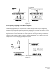

Table Of Contents

Page 9 of 90
CCT24
radio, protocol formatting must be used unless the data being sent includes addressing information that
the devices connected to the remotes/routers can use to determine the intended destination of the broad-
cast data. Protocol formatting is also required for configuration commands and responses, and sensor I/O
commands and responses. Protocol mode can be used at the base while transparent mode is used at the
remotes. The one caution about protocol mode: the length of a protocol mode message cannot exceed
the BaseSlotSize or RemoteSlotSize or the packet will be discarded. Protocol formatting details are
covered in Section 4.
The CCT24 provides two ways to switch between transparent and protocol modes. To enter protocol
mode, the /CFG input Pin 18 can be switched from logic high to low, or the EnterProtocolMode command
can be sent. When input Pin 18 is switched from logic low to high, or an ExitProtocolMode command is
sent to the primary serial input, the CCT24 will switch to transparent operation. Note that it is possible that
part of the EnterProtocolMode command will be sent over the air as transparent data.
When operating in transparent mode, two configuration parameters control when a CCT24 radio will send
the data in its transmit buffer. The MinPacketLength parameter sets the minimum number of bytes that
must be present in the transmit buffer to trigger a transmission. The TxTimeout parameter sets the maxi-
mum time data in the transmit buffer will be held before transmitting it, even if the number of data bytes is
less than MinPacketLength. The default value for MinPacketLength parameter is one and the TxTimeout
parameter is zero, so that any bytes that arrive in the CCT24 transmit buffer will be sent on the next hop.
As discussed in Section 2.8.2, it is useful to set these parameters to values greater than their defaults in
point-to-multipoint systems where some or all the remotes are in transparent mode.
2.4 SPI Port Modes
CCT24 radios can be configured to transmit and receive data through the serial peripheral interface (SPI)
port instead of the primary serial (UART) port. A CCT24 can operate as either an SPI Master or Slave.
Messages routed through the SPI port must be protocol formatted, as described in Section 4. When a
CCT24 is acting as an SPI Slave, all messages are routed through the SPI port. When a CCT24 is acting
as an SPI Master, only data messages are routed through the SPI port; radio configuration commands
and responses are routed through the primary serial (UART) port. A radio configured as an SPI Master
can use a command stored in the SPI_MasterCmdStr parameter to interrogate a Slave peripheral for
data to transmit to the base. This is especially useful where periodic I/O reporting is enabled on the
remote. Alternately, the base can send an interrogation command to the radio to fetch peripheral data.
SPI operation is configured with the SPI_Mode parameter.
2.5 RF Data Communications
At the beginning of each hop the base transmits a beacon, which always includes a synchronizing signal.
After synchronization is sent, the base will transmit any user data in its transmit buffer, unless in transpar-
ent mode the MinPacketLength and/or TxTimeout parameters have been set above their default values.
The maximum amount of user data bytes that the base can transmit per hop is limited by the BaseSlot-
Size parameter, as discussed in Section 2.8.1. If there is no user data or reception acknowledgements
(ACKs) to be sent on a hop, the base will only transmit the synchronization signal in the beacon.
The operation for remotes and routers is similar to the base, but without a synchronizing signal. The
RemoteSlotSize parameter indicates the maximum number of user data bytes a remote or router can
transmit on one hop and is a read-only value. The RemoteSlotSize is determined by the HopDuration and