Preliminary Specification Number : SP-ABR-105-A WLAN Module Data Sheet MP P/N: CMWC1ZZABR Preliminary & Confidential < Specification may be changed by Murata without notice > Murata (China) Investment Co., Ltd.
Preliminary Specification Number : SP-ABR-105-A Revision History Revision Code Draft A Date Description 2015-4-27 2019-11-14 Draft 1. Revised label marking Preliminary & Confidential < Specification may be changed by Murata without notice > Murata (China) Investment Co., Ltd.
Preliminary Specification Number : SP-ABR-105-A Contents 1. Scope ................................................................................................................................................. 1 2. Part Number / Part Composition ..................................................................................................... 1 3. Block Diagram ................................................................................................................................... 1 4.
Preliminary Specification Number: SP-ABR-105-A P. 1/14 1. Scope This product specification is applied to the IEEE802.11b/g/n WLAN module used for consumer applications. Module size Chipset Interface Reference Clock ROM Antenna Certification MSL RoHS : 22.0 x 19.0 x 2.
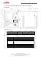
Preliminary Specification Number: SP-ABR-105-A P. 2/14 3. Construction, Dimensions, Marking and Terminal Configurations 3.1 Construction C Top view B I Bottom view L A D E W QR code F Model: ABR FCC ID: VPYCMWC1ZZABR IC: 772C-CMWC1ZZABR G H J 3.2 Dimensions (in mm) Mark L W T Min. 21.8 18.8 - Typ. 22 19 2.4 3.3 Label Marking Mark A B C D E F G H I J Name Pin.
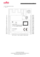
Preliminary Specification Number: SP-ABR-105-A P. 3/14 3.4 Pin assignment (top view) 4. QR code 1 2 3 4 5 6 7 8 9 10 11 12 13 QR code Model: ABR FCC ID: VPYCMWC1ZZABR IC: 772C-CMWC1ZZABR 14 15 16 17 18 19 20 21 22 23 24 Preliminary & Confidential < Specification may be changed by Murata without notice > Murata (China) Investment Co., Ltd.
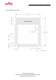
Preliminary Specification Number: SP-ABR-105-A P. 4/14 4.1 Recommended land pattern Antenna area Preliminary & Confidential < Specification may be changed by Murata without notice > Murata (China) Investment Co., Ltd.
Preliminary Specification Number: SP-ABR-105-A P. 5/14 4.2 Pin description No. Name Function I/O MW300 Pin No. MW300 Pin Function 1 GPIO_16 CON[5]: Configuration Bit I/O 30 GPIO_16 2 RESET_N Module Reset (active low) I 35 RESETn 3 GPIO_22 NC 36 GPIO_22 4 GPIO_23 Functional Button Pin (optional) 37 GPIO_23 5 GPIO_24 NC 38 GPIO_24 6 GND 7 GPIO_25 32.768 kHz Crystal Input / Oscillator Input I 39 GPIO_25 8 GPIO_26 32.
Preliminary Specification Number: SP-ABR-105-A P. 6/14 37 GPIO_10 TRSTn: JTAG Test Reset (active low) (optional) I 12 GPIO_10 4.3 Configuration pins This table shows the pins used as configuration inputs to set parameters following a reset. The definition of these pins changes immediately after reset to their usual function. To set a configuration bit to 0, attach a 100kohm resistor from the pin to ground. No external circuitry is required to set a configuration bit to 1.
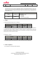
Preliminary Specification Number: SP-ABR-105-A P. 7/14 7. RF Characteristics for IEEE802.11 Conditions: 25℃, VDD33= 3.3V Items Tx Power Level 802.11b (11Mbps) 802.11g (54Mbps) 802.11n (HT20) Rx Minimum Input Level Sensitivity 802.11b (11Mbps) 802.11g (54Mbps) 802.11n (HT20) Min. Min. - Contents Power Levels Typ. Max. 20.97 23.48 22.17 Typ. Max. -76 -65 -64 Units dBm dBm dBm Units dBm dBm dBm *Test performed through Murata RF switch connector P/N: MM8030-2610. 8. Power Up Sequence 9.
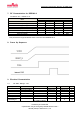
Preliminary Specification Number: SP-ABR-105-A P. 8/14 9.2 Clock Specifications (optional) 9.2.1 RC32K Specifications Parameter Frequency before calibration Startup time After-calibration frequency accuracy Temperature tolerance Duty cycle Condition Use 32.768kHz crystal as reference clock - Min. 18.6 - Typ. 31.8 0.9 Max. 39.8 - Units kHz ms 32.3 32.7 33.1 kHz 40 65 50 60 ppm/C % Min. -40 Typ. 32.768 50 12.5 - Max. 40 600 7 100 Units kHz ppm ms % pF pF kΩ 9.2.
Preliminary Specification Number: SP-ABR-105-A P. 9/14 11. OEM Guidance OEM can only use the embedded PCB antenna to guarantee regulatory compliance. Besides that, the following guides must be followed in order to get the best antenna performance. (1) Place the antenna area on the corner or edge of the main board. (2) No ground, circuit, component under the antenna area, including the reverse side of PCB. No ground area is as large as possible.
Preliminary Specification Number: SP-ABR-105-A P. 10/14 12. Package This module product is packaged in tray. 1 tray: 45pcs products 1 inner box: 6 trays with products 1 outer box: 4 inner boxes MOQ: 1080pcs Inner 撪憰敔box Outter 奜憰敔 box Preliminary & Confidential < Specification may be changed by Murata without notice > Murata (China) Investment Co., Ltd.
Preliminary Specification Number: SP-ABR-105-A P. 11/14 NOTICE 1. Storage Conditions Please use this product within 6month after receipt. - The product shall be stored without opening the packing under the ambient temperature from 5 to 35 °C and humidity from 20 ~ 70 %RH. (Packing materials, in particular, may be deformed at the temperature over 40 °C) - The product left more than 6months after reception, it needs to be confirmed the solderability before used.
Preliminary Specification Number: SP-ABR-105-A P. 12/14 When products are immersed in solvent after mounting, pay special attention to maintain the temperature difference within 100 °C. Soldering must be carried out by the above mentioned conditions to prevent products from damage. Set up the highest temperature of reflow within 260 °C. Contact Murata before use if concerning other soldering conditions.
Preliminary Specification Number: SP-ABR-105-A P. 13/14 indirectly through another device. 9. Limitation of Applications: Please contact Murata before using products for the applications listed below which require especially high reliability for the prevention of defects which might directly cause damage to the third party's life, body or property. - Aircraft equipment. - Aerospace equipment. - Undersea equipment. - Medical equipment. - Transportation equipment (vehicles, trains, ships, etc.).
Preliminary Specification Number: SP-ABR-105A P. 14/15 CAUTION PLEASE READ THIS NOTICE BEFORE USING OUR PRODUCTS. Please make sure that your product has been evaluated and confirmed from the aspect of the fitness for the specifications of our product when our product is mounted to your product.
Preliminary Specification Number: SP-ABR-105-A P. 15/15 on the content of specification sheet or approval sheet. Customer acknowledges that engineering samples may deviate from specifications and may contain defects due to their development status. We reject any liability or product warranty for engineering samples.
OEM Guidance 1. Applicable FCC rules This module is granted by Single Modular Approval. It complies to the requirements of FCC part 15C, section 15.247 rules. 2. The specific operational use conditions This module can be used in IoT devices. The input voltage to the module is nominally 3.3VDC. The operational ambient temperature of the module is -30 to 85 degree C. Only the embedded PCB antenna is allowed. Any other external antenna is prohibited. 3. Limited module procedures N/A 4.
built into a host as a portable usage, the additional RF exposure evaluation may be required as specified by 2.1093. 6. Antenna Antenna type: PCB antenna; Peak gain: -0.1dBi 7. Label and compliance information An exterior label on OEM’s end product can use wording such as the following: “Contains Transmitter Module FCC ID: VPYCMWC1ZZABR” or “Contains FCC ID: VPYCMWC1ZZABR.” 8.
The host integrator installing this module into their product must ensure that the final composite product complies with the FCC requirements by a technical assessment or evaluation to the FCC rules, including the transmitter operation and should refer to guidance in KDB 996369. For host products with certified modular transmitter, the frequency range of investigation of the composite system is specified by rule in Sections 15.