
Datasheet


BWR-15/670-D12A-C
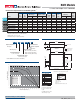
±15 ±670 75 100 ±0.3% ±0.5% 24 9-36 30/979 82% 83% C4, P7
BWR-12/830-D12A-C
±12 ±830 75 100 ±0.3% ±0.5% 24 9-36 30/1000 81.5% 83% C4, P7
BWR-5/1500-D5A-C
±5 ±1500 50 100 ±0.5% ±1.0% 5 4.7-7.5 75/3750 79% 80% C4, P7
BWR-5/1700-D12A-C
±5 ±1700 75 100 ±0.3% ±0.5% 24 9-36 15/753 80.5% 83% C4, P7
BWR-5/1700-D48A-C
±5 ±1700 75 100 ±0.3% ±0.5% 48 18-75 15/377 81% 83% C4, P7
BWR-12/625-D5A-C
±12 ±625 75 120 ±0.5% ±1.0% 5 4.7-7.5 75/3750 79% 81% C4, P7
BWR-12/830-D48A-C
±12 ±830 75 100 ±0.4% ±0.5% 48 18-75 15/510 81% 83% C4, P7
BWR-15/500-D5A-C
±15 ±500 75 150 ±0.5% ±1.0% 5 4.7-7.5 75/3659 80% 82% C4, P7
BWR-15/670-D48A-C
±15 ±670 75 100 ±0.3% ±0.5% 48 18-75 15/484 82% 84% C4, P7
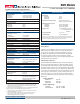
Notes:
For "D5A" and "D12A" models,
the case is connected to pin
2 (–V
IN).
For "D48A" models, the case is
connected to pin 1 (+V
IN).
BOTTOM V IE W
1.800
(45.72)
0.10
(2.54)
2.00
(50.80)
8
5
6
7
0.40
(10.16)
0.200
(5.08)
0.400
(10.16)
0.100
(2.54)
1
2
4
METAL CASE
INSULATED BASE
0.040 ±0.002 DIA .
(1.016 ±0.051)
2.00
(50.80)
0.20 MIN
(5.08)
0.45
(11.43)
1.200
(30.48)
3 E Q . S P . @
0.400 (10.16)
Case C4
➀ Typical at TA = +25°C under nominal line voltage and full-load conditions unless otherwise noted.
➁ Ripple/Noise (R/N) measured over a 20MHz bandwidth.
➂ Balanced loads, 20% to 100% load.
➃ Nominal line voltage, no-load/full-load conditions.
Nominal Output Voltages:
±5, ±12 or ±15 Volts
Maximum Output Current
in mA from each output
Input Voltage Range:
D5 = 4.7-7.5 Volts (5V nominal)
D12 = 9-36 Volts (24V nominal)
D48 = 18-75 Volts (48V nominal)
Wide Range Input
Output Confi guration:
B = Bipolar
12B WR 830 D48 A-
/
-
A-Series
High Reliability
Performance Specifi cations and Ordering Guide
➀
IOUT
(mA)
R/N (mVp-p) ➁
Load ➂
V
OUT
(Volts)
Output
Package
(Case,
Pinout)
Effi ciencyRegulation (Max.)
Line
V
IN Nom.
(Volts)
Range
(Volts)
Model
Input
IIN
➃
(mA)
Max.
Typ.
Typ.
Min.
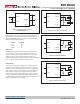
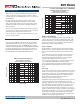
Output Power (Watts)
Ambient Temperature (
°
C)
20
19
18
17
16
15
14
13
12
11
10
9
8
7
6
5
4
3
2
1
0
A
B
BWR-5/1500-D5A C
BWR-5/1700-D12A B
BWR-5/1700-D48A B
BWR-12/625-D5A C
BWR-12/830-D12A A
BWR-12/830-D48A A
BWR-15/500-D5A C
BWR-15/670-D12A A
BWR-15/670-D48A A
–40 0 40 45 50 55 60 65 70 75 80 85 90 95 100
C
PART NUMBER STRUCTURE
MECHANICAL SPECIFICATIONS
TEMPERATURE DERATING
I/O Connections
Pin Function P7
1 +Input
2 –Input
3 No Pin
4 On/Off Control
5 +Output
6 Common
7 –Output
8Trim
- C
RoHS-6 Hazardous
Substance Compliant*
* Contact Murata Power Solutions for availability
Third Angle Projection
Dimensions are in inches (mm) shown for ref. only.
Components are shown for reference only.
Tolerances (unless otherwise specified):
.XX ± 0.02 (0.5)
.XXX ± 0.010 (0.25)
Angles ± 2˚
BWR Models
15-20W, Dual Output DC/DC Converters
MDC_BWR15_20.D01 Page 2 of 6
www.murata-ps.com/support