
Datasheet


Absolute Maximum Ratings
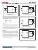
Floating Outputs
Since these are isolated DC/DC converters, their outputs are "fl oating." Any
BWR model may be confi gured to produce an output of 10V, 24V or 30V
(for
±5V, ±12V or ±15V models, respectively) by applying the load across
the +Output and –Output pins (pins 5 and 7), with either output grounded.
The Common pin (pin 6) should be left open. Minimum 20% loading is
recommended under these conditions. The total output voltage span may be
externally trimmed as described below.
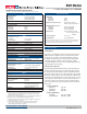
Filtering and Noise Reduction
All A-Series BWR 15-20 Watt DC/DC Converters achieve their rated ripple
and noise specifi cations without the use of external input/output capacitors.
In critical applications, input/output ripple and noise may be further reduced
by installing electrolytic capacitors across the input terminals and/or low-ESR
tantalum or electrolytic capacitors across the output terminals. Output capac-
itors should be connected between their respective output pin (pin 5 or 7) and
Common (pin 6) as shown in Figure 2. The caps should be located as close
to the power converters as possible. Typical values are listed in the tables
below. In many applications, using values greater than those listed will yield
better results.
To Reduce Input Ripple
D5A Models 47µF, 16V
D12A Models 20µF, 50V
D48A Models 20µF, 100V
To Reduce Output Ripple
±5V Outputs 47µF, 10V, Low ESR
±9/12/15V Outputs 22µF, 20V, Low ESR
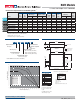
Performance/Functional Specifi cations
Typical @ TA = +25°C under nominal line voltage and full-load conditions, unless noted. ➀
➀ These converters require a minimum 20% loading on each output to maintain specifi ed
regulation. Operation under no-load conditions will not damage these devices; however
they may not meet all listed specifi cations.
➁ Application-specifi c internal input/output fi ltering can be recommended and perhaps added
internally upon request. Contact MPS Applications Engineering for details.
➂ Applying a voltage to the Control pin when no input power is applied to the converter can
cause permanent damage to the converter.
➃ "D48A" models have BASIC, "D5A" and "D12A" models have Functional insulation.
Devices can be screened or modifi ed for higher guaranteed isolation voltages.
Contact MPS Applications Engineering for details.
Input
Input Voltage Range:
D5A Models 4.7-7.5 Volts (5V nominal)
D12A Models 9-36 Volts (24V nominal)
D48A Models 18-75 Volts (48V nominal)
Input Current See Ordering Guide
Input Filter Type ➁ Pi
Overvoltage Shutdown:
D5A Models 10 Volts
D12A Models 40 Volts
D48A Models 80 Volts
Reverse-Polarity Protection Yes (Instantaneous, 10A maximum)
On/Off (Sync.) Control (Pin 4) ➂ TTL high = off, low (or open) = on
Output
VOUT Accuracy (50% load):
±5V Outputs ±1.5%, maximum
±9/12/15V Outputs ±1%, maximum
Temperature Coeffi cient ±0.02% per °C
Ripple/Noise (20MHz BW) ➁ See Ordering Guide
Line/Load Regulation See Ordering Guide
Effi ciency See Ordering Guide
Isolation Voltage ➃ 1500Vdc, minimum
Isolation Capacitance 550pF
Current Limiting Auto-recovery
Overvoltage Protection Zener/transorb clamps, magnetic feedback
Dynamic Characteristics
Transient Response (50% load step) 270µsec max. to ±1.5% of fi nal value
Switching Frequency 165kHz (±15kHz)
Environmental
Operating Temperature (ambient):
Without Derating –40 to +50/55/60°C (Model dependent)
With Derating to +100°C (See Derating Curves)
Storage Temperature –40 to +105°C
Flammability UL 94V-0
Physical
Dimensions 2" x 2" x 0.45" (51 x 51 x 11.4mm)
Shielding 5-sided
Case Connection:
D5A and D12A Models Pin 2 (–V
IN)
D48A Models Pin 1 (+V
IN)
Case Material Corrosion resistant steel with
non-conductive, epoxy-based, black
enamel fi nish and plastic baseplate
Pin Material Gold-plated copper alloy
Weight 2.7 ounces (75.6 grams)
Input Voltage:
D5A Models 12 Volts
D12A Models 44 Volts
D48A Models 88 Volts
Input Reverse-Polarity Protection Current must be <10A. Brief
duration only. Fusing recommended.
Output Overvoltage Protection
±5V Outputs 6.8 Volts, limited duration
±12V Outputs 15 Volts, limited duration
±15V Outputs 18 Volts, limited duration
Output Current Current limited. Max. current and
short-circuit duration are model
dependent.
Storage Temperature –40 to +105°C
Lead Temperature See soldering guidelines
These are stress ratings. Exposure of devices to greater than any of these conditions may
adversely affect long-term reliability. Proper operation under conditions other than those
listed in the Performance/Functional Specifi cations Table is not implied.
TECHNICAL NOTES
BWR Models
15-20W, Dual Output DC/DC Converters
MDC_BWR15_20.D01 Page 3 of 6
www.murata-ps.com/support