
Datasheet


LXDC55KAAA-205
Micro DC-DC converter
7
Dec 2014
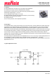
7. Detailed Description
Adjustable output voltage
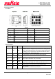
The output voltage of LXDC55K series can be adjusted from 0.8 V to 3.6 V by using a resistor (RFB) between FB
pin and GND pin. In terms of resistor value is calculated by RFB = 5.44/(Vout-0.8V) – 1.6 [kohm]
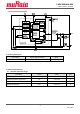
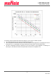
PWM Operation
At medium to heavy load currents, the device operates with pulse width modulation (PWM).
As the load current decreases, the converter enters the Power Save Mode operation reducing its switching
frequency. The device enters Power Save Mode at the boundary to discontinuous conduction mode (DCM).
Power Save Mode Operation
As the load current decreases, the converter enters Power Save Mode operation. During Power Save Mode the
converter operates with reduced switching frequency in PFM mode and with a minimum quiescent current while
maintaining high efficiency.
UVLO (Under Voltage Lock Out)
The input voltage (Vin) must reach or exceed the UVLO voltage (2.2Vtyp) before the device begins the start up
sequence even when EN pin kept high. UVLO function keeps away of an unstable operation at low Vin range
Soft Start
The device has an internal soft-start function that limits the inrush current during start-up. The soft-start system
progressively increases the switching on-time from a minimum pulse-width to that of normal operation. Because
of the function, the output voltage increases gradually from zero to nominal voltage at start-up event. The typical
soft-start time is set to 800usec.
Enable
The device starts operation when EN is set high and starts up with soft start. For proper operation, the EN pin
must be terminated to logic high and must not left floating. Pulling the EN pin to logic low forces the device
shutdown. This pin is pulled down internally to GND by 400kohm resistor.
Power Good (PG)
The device has a built-in power-good (PG) function to indicate whether the output voltage has reached its
appropriate level or not. It can sink 1 mA of current and maintain its specified logic-low level.
Over Current Protection
The device integrates a current limit function to protect internal components against heavy load or short circuit. If
the OCP event is removed, the output voltage recovers to the nominal value automatically.
Thermal Shutdown
As soon as the internal IC’s junction temperature exceeds 150 (typ), the device goes into thermal shutdown. ℃
The device continues its operation when the Internal IC’s junction temperature again falls below 130 (typ).℃
Discharge Function
To make sure the device starts up under defined conditions, the output gets discharged with a typical discharge
resistor of 200 Ω whenever the device shuts down. This happens when the device is disabled or if thermal
shutdown, under voltage lockout or over current protection is triggered.
100% Duty Cycle Operation
The device offers low input to output voltage difference by entering 100% duty cycle mode. In this mode the high
side MOSFET switch is constantly turned on. This is particularly useful in battery powered applications to achieve
longest operation time by taking full advantage of the whole battery voltage range.