!Note • This PDF catalog is downloaded from the website of Murata Manufacturing co., ltd. Therefore, it’s specifications are subject to change or our products in it may be discontinued without advance notice. Please check with our sales representatives or product engineers before ordering. • This PDF catalog has only typical specifications because there is no space for detailed specifications.
Introduction Murata Manufacturing Co., Ltd. has been developed the EMI suppression device market since the invention of 3 terminal capacitor DS310 series in 1979. Also, we have been struggling to develop and popularize new noise countermeasure technologies as well as new products in the concept of "Develop unique products", as the best solution partner of customers. We hope you can find your key device to your noise problem.
EMI Filter Selection by Application 2 aMobile Phone aLCD-TV 3 5 EMI Filter Selection by Circuits and Noise Frequency 6 Product Guide 8 BL p Chip Ferrite Bead Series Introduction Part Numbering Series Line Up Product Detail !Caution/Notice Soldering and Mounting Packaging Design Kits DL p Chip Common Mode Choke Coil Series Introduction Part Numbering Series Line Up Product Detail !Caution/Notice Soldering and Mounting Packaging Design Kits BNX Block Type EMIFILr Series Line Up Function Example Pro
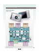
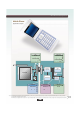
EMI Filter Selection by Application Digital Still Camera Application Sample IC Power Line Data Line Data Line BLM**B p33 p76 BLM**P p50 DLP0NS p142 NFM**P p105 BLM**B p33 p76 Flash Memory Lens Image Sensor Image Sensor Controler A/D Converter LCD Panel LCD Controler CPU (DSP,JPEG) Speaker Lens Motor Motor Driver Audio Processer MCU USB I/F Microphone Card Slot AC Adapter Power Unit USB Differential Data Line DLP0NS/11S p142 p143 Battely Storage Media AC Adapter Input Power Line
EMI Filter Selection by Application Mobile Phone Application Sample Audio Line FPC NFA18SL BLM03/BLM15 p117 DLP11S/DLP2AD p21 p23 p26 p33 p35 p50 p51 DLM11G/DLM2HG p143 p146 p140 p141 Base Band Application LCD Module Tuner/ Wireless LAN Audio RF-Module/IC DC-DC Converter Camera Module USB Line Power Line RF Module BLM03/BLM15 p21 p23 p26 p33 p35 p50 p51 p65 p71 p74 NFM18PS/PC p105 p106 DLP11S p143 !Note • This PDF catalog is downloaded from the website of Murata Manufacturing co.
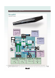
EMI Filter Selection by Application Blu-ray/DVD Application Sample IC Power Line BLM18P/18K/18EG/21P Data Line p53 p55 p61 p72 NFM18PS/PC BLM15B/15H/15G p35 p65 p74 p105 p106 Control Panel BLA p76 p79 Optical Drive Clock Line Panel Controller BLM**B/**P p33 p50 NFL18/21 p114 p116 System Memory Control CLK System Processor Imaging Processor to Power Supply Power Line CLK Audio Line Video Line Date Line Power Line Audio AD/DAC Video Encoder Decoder 1394 Transceiver Demodulatio IC Po
EMI Filter Selection by Application LCD-TV Application Sample RSDS Line DLP11S/DLP2AD p143 p146 LVDS RSDS LVDS Line Resalution Convert Gray-Scale Voltage Generater Timing Controler Scaler IP Convert DLP11S/DLP2AD p143 p146 Frame Memory Source Driver Gate Driver Display Picture Processing Engine Audio Processor Audio IN/OUT Audio Power Amp A/D Convert Back Light Video Decoder Backlight Up Convert Panel AC Converter Audio Line Picture Processing Environment IC Tuner (BS/CS/UHF) AC IN D
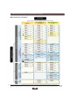
EMI Filter Selection by Circuits and Noise Frequency oChip Ferrite Bead / Chip EMIFILr Circuit Type? General Signal Line Power Line p50 BLM03P 0201/0.75-0.9A/Imp.22-33Ω p51 BLM15P Inductor Type ( Suppression Effect: Normal ) BLM02A p21 BLM03A 0201/Imp.10-1000Ω p53 BLM18P 0603/0.5-3A/Imp.30-470Ω p55 BLM21P p23 BLM15A p57 BLM31P p28 BLM18A p59 p32 BLM18T BLM18R BLM18K p61 0805/Imp.120-1000Ω p63 0805/Imp.120-1000Ω BLM21R BLM18S 0603/1.5-6A/Imp.
EMI Filter Selection by Circuits and Noise Frequency oChip Common Mode Choke Coil Circuit Type? High Speed Differential Signal Line DC Power Line High Speed Signal Line Ultra High Speed Signal Line (USB/LVDS/IEEE1394 etc.) (HDMI/DVI/Display Port etc.) p152 DLW5AH DLP0NS p152 DLW5BS DLP11SN p153 DLW21H DLP11SA p143 0504/Imp.35-90Ω p143 0504/Imp.35-330Ω 2020/0.5-5A/Imp.190-3000Ω DLW5BT p142 03025/Imp.67-120Ω 2014/0.2A/Imp.4000Ω DLW21S_HQ 0805/Imp.
Product Guide BL p Series BLM02A For General Signal BLM03A BLM15A BLM18A BLM21A BLM18T BLA2AA p20 p21 p23 p26 p28 p30 p32 p76 (4 circuits array) BLA31A p79 (4 circuits array) For High Speed Signal BLM03B BLM15B BLM18B BLM21B BLA2AB p33 p35 p38 p42 p76 (4 circuits array) BLA31B p79 For Digital Interface BLM18R BLM21R BLM03P BLM15P* p45 p47 p50 p51 10 01005 (0402) 10 70 120 10 80 70 120 10 70 120 0201 (0603) 0402 (1005) BLM18P* BLM21P* BLM31P* BLM41P* BLM18K* p57 p59
Product Guide Size Code Inch (mm) for High-GHz Band Noise Suppression Inductor Type Series NFp BLM15GG BLM15GA BLM18GG p74 p75 NFM21C NFM3DC NFM41C NFA31C p100 p101 p102 p103 p104 NFM18P For Large Current Capacitor Type (4 circuits array) NFM21P NFM3DP* NFM31P NFM41P T Circuit Filter Feed Through Type NFM55P NFE31P NFE61P p105 p106 p107 p108 p109 p110 p111 p112 p113 NFL18SP For Signal Line LC(RC) Combined Type NFL18ST NFL21S NFA18S (4 circuits array) NFA21S (4 circuits array)
Product Guide For Audio Line DL p DLM11G DLM2HG For Differential Signal Line Common Mode Choke Coils DLP0NS DLP11S DLP31S DLP2AD DLW21S DLW21H For Large Current SMD Type p142 p143 p145 p146 p147 p148 p150 p151 p152 DLW5BS* / DLW5AH DLW5BT* p153 Series BNX022* BNX023* BNX002 Lead Type Block EMIFILr p141 (2 circuits array) DLW31S BNX p140 (2 circuits array) DLP31D BNX003 BNX005 BNX012* BNX016* Common Mode Impedance (Ω) at 100MHz Size Code Inch (mm) Series p165 p165 p166 p
Chip Ferrite Bead BL 12 Part Numbering 14 Series Line Up 15 Product Detail 20 !Caution/Notice 81 Soldering and Mounting 82 Packaging 86 Design Kits 87 Microwave Absorber Block Type EMIFILr Chip Common Mode Choke Coil Series Introduction Chip EMIFILr Chip Ferrite Bead !Note • This PDF catalog is downloaded from the website of Murata Manufacturing co., ltd. Therefore, it’s specifications are subject to change or our products in it may be discontinued without advance notice.
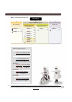
BL p Series Introduction Example of Chip Ferrite Bead BLM Series Structure Inner Electrode Chip Ferrite Bead Outer Electrode Ferrite Sheet Through Hole Chip EMIFILr Cross Section Equivalent Circuit Line Up Classification of Chip Ferrite Bead Meet High-GHz Band Noise 1600 High-GHz Band BLM_G Series Impedance (Ω) Chip Common Mode Choke Coil 1400 1200 1000 800 600 400 High BLM18Gp 200 0 BLM15Gp 1 10 100 1000 10000 Frequency (MHz) BLM_H Series BLM_E Series BLM18Hp BLM18Ep BLM15Hp
BLp Series Introduction Difference between BLM A type and B type (HG type vs HD/HB type) cComparison of Resistance Element cComparison of Impedance Curve 1200 1200 600 900 R (Ω) BLM18AG601SN1 300 600 BLM18AG601SN1 300 1 10 100 0 1000 Frequency (MHz) 1 10 100 1000 Chip EMIFILr Z (Ω) BLM18BD601SN1 BLM18BD601SN1 900 0 Chip Ferrite Bead A type: Impedance curve rises from low frequency range. Suppress noise in wide frequency range. B type: Impedance curve rises sharply.
BL p (Part Number) Part Numbering Chip Ferrite Bead BL M 18 AG 102 q w e r t N S 1 D y u i o tImpedance Expressed by three figures. The unit is in ohm (Ω) at 100MHz. The first and second figures are significant digits, and the third figure expresses the number of zeros which follow the two figures. qProduct ID Chip Ferrite Bead Product ID BL Chip Ferrite Beads yElectrode wType Expressed by a letter. Code Type A Array Type M Ferrite Bead Single Type Ex.
For General Signal p20 p21 For General Signal p33 0201 For High Speed Signal (Sharp Impedance Curve) p50 For Large Current p23 For General Signal p26 p35 0402 For High Speed Signal (Sharp Impedance Curve) p51 For Large Current BLM02AG100SN1 BLM02AG700SN1 BLM02AG121SN1 BLM03AG100SN1 BLM03AG700SN1 BLM03AG800SN1 BLM03AG121SN1 BLM03AG241SN1 BLM03AG601SN1 BLM03AG102SN1 BLM03BD750SN1 BLM03BD121SN1 BLM03BD241SN1 BLM03BD471SN1 BLM03BD601SN1 BLM03BB100SN1 BLM03BB220SN1 BLM03BB470SN1 BLM03BB750SN1 BLM0
BLp Chip Ferrite Bead Series Line Up Size (Inch) Type Part Number p65 For General Signal Chip Ferrite Bead p65 0402 For High Speed Signal For GHz (Sharp Impedance Curve) Band Noise For General Signal For Large Current p71 p74 For High-GHz Band Noise For General Signal For High Speed Signal p74 p28 Chip EMIFILr For General Signal p32 0603 For High Speed Signal (Sharp Impedance Curve) Microwave Absorber Block Type EMIFILr Chip Common Mode Choke Coil p38 p45 For Digital Interface BLM15H
BLp Chip Ferrite Bead Series Line Up Standard Type p61 For Large Current Low DC Resistance Type p63 p67 For General Signal 0603 p67 For High Speed Signal (Sharp Impedance Curve) For GHz Band Noise p67 For Digital Interface p72 For General Signal For Large Current For High-GHz Band Noise p75 p30 0805 For General Signal BLM18PG300SN1 BLM18PG330SN1 BLM18PG600SN1 BLM18PG121SN1 BLM18PG181SN1 BLM18PG221SN1 BLM18PG331SN1 BLM18PG471SN1 BLM18KG260TN1 BLM18KG700TN1 BLM18KG121TN1 BLM18KG221SN1 BLM18KG
BLp Chip Ferrite Bead Series Line Up Size (Inch) Type Part Number Chip Ferrite Bead p42 For High Speed Signal (Sharp Impedance Curve) Chip EMIFILr 0805 p47 Chip Common Mode Choke Coil For Digital Interface p55 For Large Current p57 1206 For Large Current p59 Block Type EMIFILr 1806 For Large Current p76 For General Signal p76 0804 Microwave Absorber For High Speed Signal BLM21BD121SN1 BLM21BD151SN1 BLM21BD221SN1 BLM21BD331SN1 BLM21BD421SN1 BLM21BD471SN1 BLM21BD601SN1 BLM21BD751SN1
BLp Chip Ferrite Bead Series Line Up Type Part Number p79 For General Signal 1206 p79 Rated Current 200mA 200mA 150mA 150mA 100mA 50mA 150mA 150mA 100mA 100mA 50mA Microwave Absorber Block Type EMIFILr Chip Common Mode Choke Coil Chip EMIFILr For High Speed Signal BLA31AG300SN4 BLA31AG600SN4 BLA31AG121SN4 BLA31AG221SN4 BLA31AG601SN4 BLA31AG102SN4 BLA31BD121SN4 BLA31BD221SN4 BLA31BD471SN4 BLA31BD601SN4 BLA31BD102SN4 Impedance at 100MHz/20°C at 1GHz/20°C 30ohm±25% 60ohm±25% 120ohm±25% 220ohm±25% 6
BLM Series Chip Ferrite Bead BLM02A Series (01005 Size) Ultra small 01005 size for general signal lines. ■ Dimensions ■ Equivalent Circuit 0.2±0.02 0.2±0.02 Chip Ferrite Bead 0.4±0.02 (Resistance element becomes dominant at high frequencies.) 0.10+0.04/–0.03 ■ Packaging Code Packaging Minimum Quantity D 180mm Reel Paper Tape 20000 B Bulk(Bag) 1000 : Electrode Chip EMIFILr (in mm) Refer to pages from p.82 to p.85 for mounting information.
BLM Series Chip Ferrite Bead BLM03A Series (0201 Size) 0201 size for general signal lines. ■ Dimensions ■ Equivalent Circuit Chip Ferrite Bead 0.3±0.03 0.3±0.03 0.6±0.03 (Resistance element becomes dominant at high frequencies.) 0.15±0.05 ■ Packaging Code Packaging Minimum Quantity D 180mm Reel Paper Tape 15000 J 330mm Reel Paper Tape 50000 B Bulk(Bag) 1000 (in mm) Refer to pages from p.82 to p.85 for mounting information.
BLM Series Chip Ferrite Bead BLM03A Series (0201 Size) ■ Impedance-Frequency Characteristics BLM03AG241SN1 Chip Ferrite Bead 200 Z Impedance (Ω) Impedance (Ω) 160 120 R 80 1000 400 800 300 Z R 200 X 40 0 X 100 1 10 100 Frequency (MHz) 1000 3000 1000 3000 BLM03AG601SN1 500 0 Impedance (Ω) BLM03AG121SN1 1 10 100 Frequency (MHz) Z 600 R 400 X 200 1000 3000 0 1 10 100 Frequency (MHz) 1000 3000 BLM03AG102SN1 1500 Z Impedance (Ω) Chip EMIFILr 1200 R 900 600 X 300
BLM Series Chip Ferrite Bead BLM15AG Series (0402 Size) 0402 size for general signal lines. ■ Dimensions ■ Equivalent Circuit Chip Ferrite Bead 1.0±0.05 (Resistance element becomes dominant at high frequencies.) 0.5±0.05 ■ Packaging Code Packaging Minimum Quantity D 180mm Reel Paper Tape 10000 J 330mm Reel Paper Tape 50000 B Bulk(Bag) 1000 : Electrode (in mm) Refer to pages from p.82 to p.85 for mounting information.
BLM Series Chip Ferrite Bead BLM15AG Series (0402 Size) ■ Impedance-Frequency Characteristics BLM15AG221SN1 BLM15AG601SN1 Chip Ferrite Bead BLM15AG102SN1 1200 800 400 Z 600 Z R 200 100 1 10 100 Frequency (MHz) 400 X 1000 3000 0 R 600 300 X 1 10 100 Frequency (MHz) 1000 3000 0 1 10 100 Frequency (MHz) 1000 3000 Microwave Absorber Block Type EMIFILr Chip Common Mode Choke Coil Chip EMIFILr 0 R 200 X Z 900 Impedance (Ω) Impedance (Ω) Impedance (Ω) 300 !Note • This PDF
BLM Series Chip Ferrite Bead BLM15AG_ AN Series Gold Plating (0402 Size) Au plating electrode for wire bonding mount. ■ Dimensions ■ Equivalent Circuit Chip Ferrite Bead 1.0±0.05 (Resistance element becomes dominant at high frequencies.) 0.5±0.05 ■ Packaging : Electrode (in mm) Code Packaging Minimum Quantity D 180mm Reel Paper Tape 10000 J 330mm Reel Paper Tape 50000 B Bulk(Bag) 1000 Refer to pages from p.82 to p.85 for mounting information.
BLM Series Chip Ferrite Bead BLM15AX Series (0402 Size) Low DC resistance, large current. Small characteristics change. ■ Dimensions ■ Equivalent Circuit 0.5±0.05 Chip Ferrite Bead 0.25±0.1 1.0±0.05 (Resistance element becomes dominant at high frequencies.) 0.5±0.05 ■ Packaging Code Packaging Minimum Quantity D 180mm Reel Paper Tape 10000 J 330mm Reel Paper Tape 50000 B Bulk(Bag) 1000 : Electrode Refer to pages from p.82 to p.85 for mounting information.
BLM Series Chip Ferrite Bead BLM15AX Series (0402 Size) ■ Impedance-Frequency Characteristics BLM15AX601SN1 400 Z 200 R X 100 1200 Z 600 R 400 X 200 10 100 Frequency (MHz) 1000 3000 0 1 10 100 Frequency (MHz) Z R 900 600 X 300 1000 3000 0 1 10 100 Frequency (MHz) 1000 3000 Microwave Absorber Block Type EMIFILr Chip Common Mode Choke Coil Chip EMIFILr 1 Impedance (Ω) Impedance (Ω) Impedance (Ω) 1500 800 300 0 BLM15AX102SN1 1000 Chip Ferrite Bead BLM15AX221SN1 !N
BLM Series Chip Ferrite Bead BLM18A Series (0603 Size) 0603 size for general signal lines. ■ Dimensions ■ Equivalent Circuit 0.8±0.15 Chip Ferrite Bead 0.4±0.2 1.6±0.15 (Resistance element becomes dominant at high frequencies.) 0.8±0.15 ■ Packaging Packaging D 180mm Reel Paper Tape 4000 J 330mm Reel Paper Tape 10000 B Bulk(Bag) 1000 : Electrode Refer to pages from p.82 to p.85 for mounting information.
BLM Series Chip Ferrite Bead BLM18A Series (0603 Size) ■ Impedance-Frequency Characteristics BLM18AG471SN1 BLM18AG601SN1 600 800 800 450 600 600 Chip Ferrite Bead BLM18AG331SN1 Z R 300 150 0 10 100 Frequency (MHz) R 400 200 X 1 Z 1000 3000 1000 3000 0 Impedance (Ω) Impedance (Ω) Impedance (Ω) Z 10 100 Frequency (MHz) 400 X 200 X 1 R 1000 3000 0 1 10 100 Frequency (MHz) 1000 3000 BLM18AG102SN1 Impedance (Ω) 900 Z R 600 300 X 1 10 100 Frequency (MHz) M
BLM Series Chip Ferrite Bead BLM21A Series (0805 Size) 0805 size for general signal lines. ■ Dimensions ■ Equivalent Circuit 0.85±0.2 Chip Ferrite Bead 0.5±0.2 2.0±0.2 (Resistance element becomes dominant at high frequencies.) 1.25±0.2 ■ Packaging Packaging D 180mm Reel Paper Tape 4000 J 330mm Reel Paper Tape 10000 B Bulk(Bag) 1000 EIA CODE : 0805 : Electrode Refer to pages from p.82 to p.85 for mounting information.
BLM Series Chip Ferrite Bead BLM21A Series (0805 Size) ■ Impedance-Frequency Characteristics BLM21AG471SN1 Z 600 Impedance (Ω) R 200 X 100 800 600 Impedance (Ω) 300 Impedance (Ω) BLM21AG601SN1 800 400 Z 400 R 200 Chip Ferrite Bead BLM21AG331SN1 Z R 400 X 200 X 0 1 10 100 Frequency (MHz) 1000 3000 1000 3000 0 1 10 100 Frequency (MHz) 1000 3000 0 1 10 100 Frequency (MHz) 1000 3000 BLM21AG102SN1 Chip EMIFILr 1200 Impedance (Ω) 900 Z R 600 X 300 1 10 100 Frequency
BLM Series Chip Ferrite Bead BLM18T Series (0603 Size) Thin 0603 size for general signal lines. ■ Dimensions ■ Equivalent Circuit 0.8±0.15 0.6±0.10 Chip Ferrite Bead 1.6±0.15 (Resistance element becomes dominant at high frequencies.) 0.4±0.2 ■ Packaging Code Packaging Minimum Quantity D 180mm Reel Paper Tape 10000 B Bulk(Bag) 1000 : Electrode Refer to pages from p.82 to p.85 for mounting information.
BLM Series Chip Ferrite Bead BLM03B Series (0201 Size) 0201 size for high speed signal lines. ■ Dimensions ■ Equivalent Circuit Chip Ferrite Bead 0.3±0.03 0.3±0.03 0.6±0.03 (Resistance element becomes dominant at high frequencies.) 0.15±0.05 ■ Packaging Code Packaging Minimum Quantity D 180mm Reel Paper Tape 15000 J 330mm Reel Paper Tape 50000 B Bulk(Bag) 1000 (in mm) Refer to pages from p.82 to p.85 for mounting information.
BLM Series Chip Ferrite Bead BLM03B Series (0201 Size) ■ Impedance-Frequency Characteristics BLM03BD121SN1 100 Impedance (Ω) Z R 50 0 X 1 10 100 Frequency (MHz) 1000 Impedance (Ω) 120 R X 1 10 100 Frequency (MHz) R 400 X 10 100 Frequency (MHz) 1000 1000 BLM03BB220SN1 Z R 400 X 1 10 100 Frequency (MHz) Impedance (Ω) X 50 1 10 100 Frequency (MHz) 1000 3000 1000 3000 3000 Z R 20 X 1 10 100 Frequency (MHz) 1000 3000 BLM03BB750SN1 Z Z 450 R 200 X 0 1000
BLM Series Chip Ferrite Bead BLM15B Series (0402 Size) 0402 size for high speed signal lines. ■ Dimensions ■ Equivalent Circuit Chip Ferrite Bead 1.0±0.05 (Resistance element becomes dominant at high frequencies.) 0.5±0.05 ■ Packaging : Electrode (in mm) Code Packaging Minimum Quantity D 180mm Reel Paper Tape 10000 J 330mm Reel Paper Tape 50000 B Bulk(Bag) 1000 Refer to pages from p.82 to p.85 for mounting information. Impedance (at 100MHz/20°C) Rated Current DC Resistance (max.
BLM Series Chip Ferrite Bead BLM15B Series (0402 Size) ■ Impedance-Frequency Characteristics (Main Items) BLM15BD Series BLM15BB Series 800 BLM15BB221SN1 2000 600 Impedance (Ω) BLM15BD182SN1 Impedance (Ω) 1500 BLM15BD102SN1 1000 BLM15BD601SN1 BLM15BB100SN1 200 BLM15BB050SN1 0 0 1 10 100 Frequency (MHz) 1000 3000 1 BLM15BA Series 10 100 Frequency (MHz) 1000 3000 1000 3000 BLM15BA Series 5000 1000 800 4000 BLM15BA330SN1 BLM15BA750SN1 BLM15BA220SN1 Impedance (Ω) Impedance (Ω) 6
BLM Series Chip Ferrite Bead BLM15B Series (0402 Size) ■ Impedance-Frequency Characteristics BLM15BB050SN1 2500 BLM15BB100SN1 30 60 25 50 Chip Ferrite Bead BLM15BD182SN1 1500 1000 X 500 0 20 15 Z 10 X 5 1 10 100 Frequency (MHz) 1000 0 3000 10 100 Frequency (MHz) 1000 120 300 100 250 Z 20 0 3000 BLM15BB470SN1 BLM15BB220SN1 30 X 10 R 1 40 R 1 10 100 Frequency (MHz) 1000 3000 1000 3000 BLM15BB750SN1 400 Chip EMIFILr R Impedance (Ω) Impedance (Ω) 2000 Impedanc
BLM Series Chip Ferrite Bead BLM18B Series (0603 Size) 0603 size for high speed signal lines. ■ Dimensions ■ Equivalent Circuit 0.8±0.15 Chip Ferrite Bead 0.4±0.2 1.6±0.15 (Resistance element becomes dominant at high frequencies.) 0.8±0.15 ■ Packaging : Electrode Minimum Quantity Code Packaging D 180mm Reel Paper Tape 4000 J 330mm Reel Paper Tape 10000 B Bulk(Bag) 1000 Refer to pages from p.82 to p.85 for mounting information.
BLM Series Chip Ferrite Bead BLM18B Series (0603 Size) ■ Impedance-Frequency Characteristics (Main Items) BLM18BB Series BLM18BD Series 2800 250 BLM18BD182SN1 200 BLM18BD152SN1 BLM18BD102SN1 BLM18BD601SN1 BLM18BD471SN1 BLM18BD421SN1 BLM18BD331SN1 BLM18BD221SN1 BLM18BD151SN1 1400 Impedance (Ω) 150 BLM18BB470SN1 BLM18BB220SN1 100 BLM18BB100SN1 BLM18BD121SN1 700 BLM18BB050SN1 BLM18BD470SN1 50 0 0 1 10 100 Frequency (MHz) 1000 1 3000 10 100 Frequency (MHz) 1000 3000 1000 3000 BLM18BA
BLM Series Chip Ferrite Bead BLM18B Series (0603 Size) ■ Impedance-Frequency Characteristics BLM18BD331SN1 BLM18BD221SN1 Chip Ferrite Bead BLM18BD421SN1 900 500 1000 Z R 300 200 Impedance (Ω) 750 Impedance (Ω) Impedance (Ω) 400 600 Z R 300 X X Z R 500 X 250 100 0 1 10 100 Frequency (MHz) 1000 0 3000 BLM18BD471SN1 1 10 100 Frequency (MHz) 1000 BLM18BD601SN1 1200 0 3000 X 300 Chip Common Mode Choke Coil 10 100 Frequency (MHz) 1000 0 3000 Z 1500 Impedance (Ω) Impedan
BLM Series Chip Ferrite Bead BLM18B Series (0603 Size) ■ Impedance-Frequency Characteristics BLM18BB121SN1 X R 100 1 10 100 Frequency (MHz) 1000 0 3000 1 10 100 Frequency (MHz) 1000 Z X 150 R 600 400 X 200 1 10 100 Frequency (MHz) 1000 0 3000 BLM18BB471SN1 1000 3000 900 Z 1000 3000 R X 600 300 1 10 100 Frequency (MHz) 1000 0 3000 BLM18BA050SN1 2000 100 Frequency (MHz) 1200 Z Impedance (Ω) Impedance (Ω) 300 10 1500 800 R 1 BLM18BB331SN1 1000 450 X 0 30
BLM Series Chip Ferrite Bead BLM21B Series (0805 Size) 0805 size for high speed signal lines. ■ Dimensions ■ Equivalent Circuit 0.85±0.2 *1 Chip Ferrite Bead 0.5±0.2 *2 2.0±0.2 (Resistance element becomes dominant at high frequencies.) 1.25±0.2 ■ Packaging *1 BLM21BD222SN1 / 21BD272SN1 :1.25±0.2 • All except BLM21BD222SN1/21BD272SN1 *2 BLM21BD272SN1: 0.3±0.
BLM Series Chip Ferrite Bead BLM21B Series (0805 Size) ■ Impedance-Frequency Characteristics (Main Items) BLM21BD Series BLM21BB Series 2000 3200 BLM21BD272SN1 BLM21BD222SN1 BLM21BD222TN1 BLM21BD182SN1 1600 1600 BLM21BB471SN1 BLM21BD471SN1 BLM21BD421SN1 BLM21BD331SN1 BLM21BD221SN1 800 BLM21BB331SN1 1200 Chip Ferrite Bead BLM21BD152SN1 BLM21BD102SN1 BLM21BD751SN1 BLM21BD601SN1 Impedance (Ω) Impedance (Ω) 2400 BLM21BB201SN1 BLM21BB221SN1 BLM21BB750SN1 BLM21BB151SN1 800 BLM21BB121SN1 BLM21BB6
BLM Series Chip Ferrite Bead BLM21B Series (0805 Size) ■ Impedance-Frequency Characteristics BLM21BD222SN1 BLM21BD272SN1 3000 R 1800 X 1200 25 Z 2500 Impedance (Ω) Z Impedance (Ω) Impedance (Ω) 30 3000 2400 Chip Ferrite Bead BLM21BB050SN1 3500 Z 2000 R 1500 X 1000 600 1 10 100 Frequency (MHz) 1000 0 3000 BLM21BB600SN1 100 Frequency (MHz) 1000 200 X 100 10 100 Frequency (MHz) 1000 BLM21BB151SN1 R 200 X 100 Frequency (MHz) 1000 3000 1000 3000 1000 3000 Z 300 R
BLM Series Chip Ferrite Bead BLM18R Series (0603 Size) For digital I/F. Reduce the distortion of waveform created by resonance. ■ Dimensions ■ Equivalent Circuit Chip Ferrite Bead 1.6±0.15 (Resistance element becomes dominant at high frequencies.) 0.8±0.15 ■ Packaging Minimum Quantity Code Packaging D 180mm Reel Paper Tape 4000 J 330mm Reel Paper Tape 10000 B Bulk(Bag) 1000 : Electrode (in mm) Refer to pages from p.82 to p.85 for mounting information.
BLM Series Chip Ferrite Bead BLM18R Series (0603 Size) ■ Impedance-Frequency Characteristics BLM18RK102SN1 1000 1200 750 900 Impedance (Ω) Impedance (Ω) Chip Ferrite Bead BLM18RK601SN1 Z 500 R Z R 600 X 300 250 X 1 10 100 Frequency (MHz) 1000 3000 0 1 10 100 Frequency (MHz) 1000 3000 Microwave Absorber Block Type EMIFILr Chip Common Mode Choke Coil Chip EMIFILr 0 !Note • This PDF catalog is downloaded from the website of Murata Manufacturing co., ltd.
BLM Series Chip Ferrite Bead BLM21R Series (0805 Size) For digital I/F. Reduce the distortion of waveform created by resonance. ■ Dimensions ■ Equivalent Circuit Chip Ferrite Bead 2.0±0.2 (Resistance element becomes dominant at high frequencies.) 1.25±0.2 ■ Packaging Minimum Quantity Code Packaging D 180mm Reel Paper Tape 4000 J 330mm Reel Paper Tape 10000 B Bulk(Bag) 1000 EIA CODE : 0805 : Electrode (in mm) Refer to pages from p.82 to p.85 for mounting information.
BLM Series Chip Ferrite Bead BLM21R Series (0805 Size) ■ Impedance-Frequency Characteristics BLM21RK102SN1 1000 1200 750 900 Impedance (Ω) Impedance (Ω) Chip Ferrite Bead BLM21RK601SN1 500 Z R 250 10 100 Frequency (MHz) X 300 X 1 R 600 1000 3000 0 1 10 100 Frequency (MHz) 1000 3000 Microwave Absorber Block Type EMIFILr Chip Common Mode Choke Coil Chip EMIFILr 0 Z !Note • This PDF catalog is downloaded from the website of Murata Manufacturing co., ltd.
EMI Suppression BLMppR Series Effect Waveform Distortion Suppressing Performance of BLMppR Series Measuring Circuits Measuring Point AC04 Type of Filter Chip Ferrite Bead 1MHz AC00 Pattern20cm Filter EMI Suppression Effect / Description Signal waveform (100nsec/div, 2V/div) Expand (10nsec/div, 2V/div) Spectrum 85 Initial (No filter) 75 70 Chip EMIFILr Level (dBµV) 80 65 60 55 50 45 30 50 100 150 200 250 Frequency (MHz) 300 100 150 200 250 Frequency (MHz) 300 100 150 200 250 Frequenc
BLM Series Chip Ferrite Bead BLM03P Series (0201 Size) 0201 size for power lines. ■ Dimensions ■ Equivalent Circuit 0.3±0.03 0.3±0.03 Chip Ferrite Bead 0.6±0.03 (Resistance element becomes dominant at high frequencies.) 0.15±0.05 ■ Packaging : Electrode Chip EMIFILr (in mm) Code Packaging Minimum Quantity D 180mm Reel Paper Tape 15000 J 330mm Reel Paper Tape 50000 B Bulk(Bag) 1000 Refer to pages from p.82 to p.85 for mounting information.
BLM Series Chip Ferrite Bead BLM15P Series (0402 Size) 0402 size for power lines. ■ Dimensions ■ Equivalent Circuit Chip Ferrite Bead 1.0±0.05 (Resistance element becomes dominant at high frequencies.) 0.5±0.05 ■ Packaging : Electrode (in mm) Code Packaging Minimum Quantity D 180mm Reel Paper Tape 10000 J 330mm Reel Paper Tape 50000 B Bulk(Bag) 1000 Refer to pages from p.82 to p.85 for mounting information. Part Number Impedance (at 100MHz/20°C) Rated Current DC Resistance (max.
BLM Series Chip Ferrite Bead BLM15P Series (0402 Size) ■ Impedance-Frequency Characteristics BLM15PG100SN1 BLM15PD300SN1 15 120 90 45 Z Impedance (Ω) Impedance (Ω) BLM15PD600SN1 60 R 10 5 Impedance (Ω) Chip Ferrite Bead 20 Z 30 R X Z 60 R X 30 15 X 0 1 10 100 Frequency (MHz) 1000 0 3000 BLM15PD800SN1 Chip EMIFILr 100 Frequency (MHz) 1000 3000 1000 3000 0 1 10 100 Frequency (MHz) 1000 3000 240 120 180 Impedance (Ω) Impedance (Ω) 10 BLM15PD121SN1 160 Z 80 R X
BLM Series Chip Ferrite Bead BLM18P Series (0603 Size) 0603 size for power lines. ■ Dimensions ■ Equivalent Circuit Chip Ferrite Bead 1.6±0.15 (Resistance element becomes dominant at high frequencies.) 0.8±0.15 ■ Packaging : Electrode (in mm) Minimum Quantity Code Packaging D 180mm Reel Paper Tape 4000 J 330mm Reel Paper Tape 10000 B Bulk(Bag) 1000 Refer to pages from p.82 to p.85 for mounting information. Part Number Impedance (at 100MHz/20°C) Rated Current DC Resistance (max.
BLM Series Chip Ferrite Bead BLM18P Series (0603 Size) ■ Impedance-Frequency Characteristics BLM18PG300SN1 BLM18PG330SN1 R 20 X Z 30 R 15 1 10 100 Frequency (MHz) 1000 0 3000 BLM18PG121SN1 X 1 10 100 Frequency (MHz) Impedance (Ω) R 100 50 100 Frequency (MHz) Chip Common Mode Choke Coil 1000 100 Frequency (MHz) 1000 3000 1000 3000 300 R 140 0 3000 Z R 200 100 X 1 10 100 Frequency (MHz) 1000 3000 1000 3000 0 1 10 100 Frequency (MHz) BLM18PG471SN1 600 800 600
BLM Series Chip Ferrite Bead BLM21P Series (0805 Size) 0805 size for power lines. ■ Dimensions ■ Equivalent Circuit Chip Ferrite Bead 2.0±0.2 (Resistance element becomes dominant at high frequencies.) 1.25±0.2 ■ Packaging EIA CODE : 0805 : Electrode (in mm) Minimum Quantity Code Packaging D 180mm Reel Paper Tape 4000 J 330mm Reel Paper Tape 10000 B Bulk(Bag) 1000 Refer to pages from p.82 to p.85 for mounting information.
BLM Series Chip Ferrite Bead BLM21P Series (0805 Size) ■ Impedance-Frequency Characteristics BLM21PG220SN1 BLM21PG300SN1 120 R 20 90 45 Z X Impedance (Ω) 30 Impedance (Ω) BLM21PG600SN1 60 Impedance (Ω) Chip Ferrite Bead 40 Z 30 R 10 15 0 0 X Z 60 R 30 X 1 10 100 Frequency (MHz) 1000 3000 BLM21PG221SN1 1000 3000 1000 3000 1 10 100 Frequency (MHz) 1000 3000 Impedance (Ω) 450 Z 200 R 100 Z R 300 150 X X 1 10 100 Frequency (MHz) 1000 3000 0 1 10 100 Frequen
BLM Series Chip Ferrite Bead BLM31P Series (1206 Size) 1206 size for power lines. ■ Dimensions ■ Equivalent Circuit Chip Ferrite Bead 3.2±0.2 (Resistance element becomes dominant at high frequencies.) 1.6±0.2 ■ Packaging : Electrode (in mm) Code Packaging Minimum Quantity L 180mm Reel Embossed Tape 3000 K 330mm Reel Embossed Tape 10000 B Bulk(Bag) 1000 Refer to pages from p.82 to p.85 for mounting information.
BLM Series Chip Ferrite Bead BLM31P Series (1206 Size) ■ Impedance-Frequency Characteristics BLM31PG330SN1 BLM31PG500SN1 45 200 Z 60 Impedance (Ω) Impedance (Ω) BLM31PG121SN1 80 Z R 30 X 15 150 Impedance (Ω) Chip Ferrite Bead 60 R 40 X Z R 100 20 50 0 0 X 0 1 10 100 Frequency (MHz) 1000 3000 BLM31PG391SN1 100 Frequency (MHz) 1000 3000 1000 3000 1 10 100 Frequency (MHz) 1000 3000 800 600 Impedance (Ω) 450 Impedance (Ω) 10 BLM31PG601SN1 600 Chip EMIFILr 1 Z R 30
BLM Series Chip Ferrite Bead BLM41P Series (1806 Size) 1806 size for power lines. ■ Dimensions ■ Equivalent Circuit Chip Ferrite Bead 4.5±0.2 (Resistance element becomes dominant at high frequencies.) 1.6±0.2 ■ Packaging : Electrode (in mm) Code Packaging Minimum Quantity L 180mm Reel Embossed Tape 2500 K 330mm Reel Embossed Tape 8000 B Bulk(Bag) 1000 Refer to pages from p.82 to p.85 for mounting information. Part Number Impedance (at 100MHz/20°C) Rated Current DC Resistance (max.
BLM Series Chip Ferrite Bead BLM41P Series (1806 Size) ■ Impedance-Frequency Characteristics BLM41PG600SN1 BLM41PG750SN1 Chip Ferrite Bead 100 BLM41PG181SN1 400 100 Z 50 X Impedance (Ω) R 25 300 75 Z Impedance (Ω) Impedance (Ω) 75 R 50 X 200 Z R 25 100 0 0 X 0 1 10 100 Frequency (MHz) 1000 3000 BLM41PG471SN1 450 Impedance (Ω) 100 Frequency (MHz) 1000 3000 1000 3000 1 10 100 Frequency (MHz) 1000 3000 1200 900 Z Impedance (Ω) Chip EMIFILr 10 BLM41PG102SN1 600
BLM Series Chip Ferrite Bead BLM18K Series (0603 Size) 6A Max, high performance type for power lines up to 600ohm. ■ Dimensions ■ Equivalent Circuit Chip Ferrite Bead 0.8±0.15 T (Resistance element becomes dominant at high frequencies.) 0.4±0.2 Part Number T BLM18KG_TN 0.6±0.15 BLM18KG_SN 0.8±0.15 ■ Packaging : Electrode (in mm) Minimum Quantity Code Packaging D 180mm Reel Paper Tape 4000 J 330mm Reel Paper Tape 10000 B Bulk(Bag) 1000 Refer to pages from p.82 to p.
BLM Series Chip Ferrite Bead BLM18K Series (0603 Size) ■ Impedance-Frequency Characteristics BLM18KG260TN1 BLM18KG700TN1 75 R 20 X 1 10 100 Frequency (MHz) 1 10 100 Frequency (MHz) 1000 Impedance (Ω) R 200 100 1 10 100 Frequency (MHz) X 1 10 3000 600 Z R 300 1000 3000 0 1000 3000 1000 3000 800 Z R 400 200 X 1000 100 Frequency (MHz) BLM18KG471SN1 150 X R 100 0 3000 450 Z Z 50 600 300 Impedance (Ω) X BLM18KG331SN1 400 Chip EMIFILr 50 0 3000 BLM18KG221SN
BLM Series Chip Ferrite Bead BLM18S Series (0603 Size) 6A Max, high performance type for power lines. ■ Dimensions ■ Equivalent Circuit (Resistance element becomes dominant at high frequencies.) 0.4±0.2 ■ Packaging : Electrode (in mm) Code Packaging Minimum Quantity D 180mm Reel Paper Tape 10000 J 330mm Reel Paper Tape 30000 B Bulk(Bag) 1000 Refer to pages from p.82 to p.85 for mounting information. Part Number Impedance (at 100MHz/20°C) Rated Current DC Resistance (max.
BLM Series Chip Ferrite Bead BLM18S Series (0603 Size) ■ Impedance-Frequency Characteristics BLM18SG260TN1 BLM18SG700TN1 X 10 150 R 50 X 25 100 Frequency (MHz) 1000 0 3000 BLM18SG221TN1 X 50 1 10 100 Frequency (MHz) 1000 3000 1000 3000 0 1 10 100 Frequency (MHz) 1000 3000 400 Z Z 250 R 300 R 200 Impedance (Ω) Impedance (Ω) R 100 BLM18SG331TN1 300 Chip EMIFILr Impedance (Ω) Impedance (Ω) R 1 Z 75 20 10 200 Z Z 30 0 BLM18SG121TN1 100 Impedance (Ω) Chip Ferr
BLM Series Chip Ferrite Bead BLM15H Series (0402 Size) 0402 size for GHz band noise. ■ Dimensions ■ Equivalent Circuit Chip Ferrite Bead 1.0±0.05 (Resistance element becomes dominant at high frequencies.) 0.5±0.05 ■ Packaging Code Packaging Minimum Quantity D 180mm Reel Paper Tape 10000 J 330mm Reel Paper Tape 50000 B Bulk(Bag) 1000 : Electrode (in mm) Refer to pages from p.82 to p.85 for mounting information.
BLM Series Chip Ferrite Bead BLM15H Series (0402 Size) ■ Impedance-Frequency Characteristics BLM15HG601SN1 BLM15HG102SN1 Chip Ferrite Bead 1200 BLM15HD601SN1 2000 1800 1500 1600 Z R 600 1200 Z R 900 600 300 X 10 100 Frequency (MHz) 1000 3000 BLM15HD102SN1 Impedance (Ω) Impedance (Ω) Chip EMIFILr 2000 Z R 1000 X 1 10 100 Frequency (MHz) 1000 3000 100 Frequency (MHz) 1000 3000 R 800 3000 600 Z R 2000 X 0 X 1 10 100 Frequency (MHz) 10 3000 Z R 400 X 200 1 1000
BLM Series Chip Ferrite Bead BLM18H Series (0603 Size) 0603 size for GHz band noise. ■ Dimensions ■ Equivalent Circuit 1.6±0.15 Chip Ferrite Bead 0.8±0.15 0.4±0.2 (Resistance element becomes dominant at high frequencies.) 0.8±0.15 ■ Packaging Minimum Quantity Code Packaging D 180mm Reel Paper Tape 4000 J 330mm Reel Paper Tape 10000 B Bulk(Bag) 1000 : Electrode Refer to pages from p.82 to p.85 for mounting information.
BLM Series Chip Ferrite Bead BLM18H Series (0603 Size) ■ Impedance-Frequency Characteristics (Main Items) BLM18HD Series BLM18HB Series 1600 BLM18HB331SN1 1200 BLM18HD102SN1 2000 BLM18HD601SN1 BLM18HB121SN1 400 0 1 10 100 Frequency (MHz) 1000 3000 1 BLM18HK102SN1 1200 BLM18HK601SN1 1000 3000 BLM18HK471SN1 Derating BLM18HK331SN1 800 Derated Current [mA] 400 0 1 10 100 Frequency (MHz) 1000 3000 600 500 BLM18HE601SN1 BLM18HE102SN1 BLM18HE152SN1 400 85 125 Operating Temperature [°C
BLM Series Chip Ferrite Bead BLM18H Series (0603 Size) ■ Impedance-Frequency Characteristics BLM18HD601SN1 2000 1500 1500 R 1000 X 500 500 3000 2000 Z R 1000 X X 1 10 100 Frequency (MHz) 1000 BLM18HB121SN1 1 10 100 Frequency (MHz) 1000 1000 600 750 Z 400 R 200 0 3000 BLM18HB221SN1 800 Impedance (Ω) Impedance (Ω) 0 3000 10 100 Frequency (MHz) R 500 Z 10 100 Frequency (MHz) 1000 0 3000 BLM18HK331SN1 X 10 Impedance (Ω) Z R 300 150 1000 10 100 Frequency (MHz
EMI Suppression Effect BLMppH Series Testing Circuit Noise Suppression in UHF Range Chip Ferrite Bead 74HCU04 74AC04 Measured radiation at 3m distance 74HC00 BLM 10MHz Type of Filter EMI Suppression Effect / Description 70 Level (dBµV/m) 60 Chip EMIFILr Initial (No filter) 50 40 30 20 10 300 400 500 600 700 800 Frequency (MHz) 900 1000 70 Current BLM are effective in suppressing noise in the range between 300MHz and 700MHz.
BLM Series Chip Ferrite Bead BLM15E Series (0402 Size) For GHz band noise, also capable to large current. ■ Dimensions ■ Equivalent Circuit Chip Ferrite Bead 1.0±0.05 (Resistance element becomes dominant at high frequencies.) 0.5±0.05 ■ Packaging : Electrode (in mm) Code Packaging Minimum Quantity D 180mm Reel Paper Tape 10000 J 330mm Reel Paper Tape 50000 B Bulk(Bag) 1000 Refer to pages from p.82 to p.85 for mounting information.
BLM Series Chip Ferrite Bead BLM18E Series (0603 Size) For GHz band noise, also capable to large current. ■ Dimensions ■ Equivalent Circuit 0.8±0.15 T Chip Ferrite Bead 1.6±0.15 (Resistance element becomes dominant at high frequencies.) 0.4±0.2 ■ Packaging Part Number T BLM18EGpppTN1 0.5±0.15 BLM18EGpppSN1 0.8±0.
BLM Series Chip Ferrite Bead BLM18E Series (0603 Size) ■ Impedance-Frequency Characteristics BLM18EG121SN1 80 40 X 10 100 Frequency (MHz) 1000 X 1 10 100 Frequency (MHz) 1000 0 3000 X 100 1 10 100 Frequency (MHz) 300 R X 150 1000 0 3000 BLM18EG471SN1 1 10 100 Frequency (MHz) 1000 3000 1000 3000 560 Z Impedance (Ω) R X 700 450 Impedance (Ω) 200 R BLM18EG391TN1 600 Z Z 200 100 BLM18EG331TN1 300 Impedance (Ω) 80 0 3000 400 Z 420 R 280 140 1 10 100 Frequen
BLM Series Chip Ferrite Bead BLM15G Series (0402 Size) Available up to high-GHz band noise. ■ Dimensions ■ Equivalent Circuit 0.5±0.05 Chip Ferrite Bead 0.25±0.1 1.0±0.05 (Resistance element becomes dominant at high frequencies.) 0.5±0.05 ■ Packaging Code Packaging Minimum Quantity D 180mm Reel Paper Tape 10000 J 330mm Reel Paper Tape 50000 B Bulk(Bag) 1000 : Electrode Chip EMIFILr (in mm) Refer to pages from p.82 to p.85 for mounting information.
BLM Series Chip Ferrite Bead BLM18G Series (0603 Size) Available up to high-GHz band noise. ■ Dimensions ■ Equivalent Circuit 1.6±0.1 Chip Ferrite Bead 0.8±0.1 0.35±0.15 (Resistance element becomes dominant at high frequencies.) 0.8±0.1 ■ Packaging : Electrode Minimum Quantity Code Packaging D 180mm Reel Paper Tape 4000 J 330mm Reel Paper Tape 10000 B Bulk(Bag) 1000 Refer to pages from p.82 to p.85 for mounting information.
BLA Series Chip Ferrite Bead BLA2AA/BLA2AB Series (0804 Size) 4-lines array, 0804 size. ■ Equivalent Circuit (2) (3) (4) (5) (6) (7) (8) 2.0±0.2 (4) (5) (6) (7) No polarity. (8) Packaging Minimum Quantity D 180mm Reel Paper Tape 10000 J 330mm Reel Paper Tape 50000 B Bulk(Bag) 1000 0.5±0.1 (in mm) Refer to pages from p.82 to p.85 for mounting information.
BLA Series Chip Ferrite Bead BLA2AA/BLA2AB Series (0804 Size) ■ Impedance-Frequency Characteristics (Main Items) BLA2ABD Series 1600 BLA2ABD102SN4 BLA2ABD601SN4 Chip Ferrite Bead Impedance (Ω) 1200 BLA2ABD471SN4 800 BLA2ABD221SN4 BLA2ABD121SN4 400 BLA2ABD750SN4 0 1 10 100 Frequency (MHz) 1000 3000 ■ Impedance-Frequency Characteristics BLA2AAG221SN4 BLA2AAG601SN4 200 400 800 150 300 600 Chip EMIFILr BLA2AAG121SN4 200 X X 1 10 100 Frequency (MHz) 1000 0 3000 BLA2AAG102SN4 10 10
BLA Series Chip Ferrite Bead BLA2AA/BLA2AB Series (0804 Size) ■ Impedance-Frequency Characteristics BLA2ABD471SN4 BLA2ABD601SN4 X 10 100 Frequency (MHz) R 600 400 1000 3000 0 1 10 100 Frequency (MHz) X 400 X 200 R 800 1000 3000 0 1 10 100 Frequency (MHz) 1000 3000 Microwave Absorber Block Type EMIFILr Chip Common Mode Choke Coil Chip EMIFILr 1 Z 1200 Impedance (Ω) Impedance (Ω) Impedance (Ω) Chip Ferrite Bead R 400 200 1600 Z 800 Z 600 0 BLA2ABD102SN4 1000 800 !
BLA Series Chip Ferrite Bead BLA31A/BLA31B Series (1206 Size) 4-lines array, 1206 size. ■ Equivalent Circuit (2) (3) (4) (5) (6) (7) (8) (2) (3) (4) (5) (6) (7) No polarity. (8) ■ Packaging 0.8±0.2 0.4±0.2 (1) 1.6±0.2 0.3±0.2 (1) Chip Ferrite Bead ■ Dimensions Minimum Quantity Code Packaging D 180mm Reel Paper Tape 4000 J 330mm Reel Paper Tape 10000 B Bulk(Bag) 1000 0.8±0.1 : Electrode (in mm) Refer to pages from p.82 to p.85 for mounting information.
BLA Series Chip Ferrite Bead BLA31A/BLA31B Series (1206 Size) ■ Impedance-Frequency Characteristics BLA31AG300SN4 BLA31AG600SN4 BLA31AG121SN4 200 80 Z Z R 20 X 10 1 10 100 Frequency (MHz) 1000 Impedance (Ω) Impedance (Ω) Chip EMIFILr 150 X 1 10 100 Frequency (MHz) 1000 0 3000 Impedance (Ω) R 150 X X 1 10 100 Frequency (MHz) 1000 1 10 100 Frequency (MHz) 1000 BLA31BD601SN4 100 Frequency (MHz) 1000 3000 1000 3000 1000 3000 Z R 600 0 3000 X 1 10 100 Frequency (M
Chip Ferrite Bead !Caution/Notice !Caution ● Soldering and Mounting 1. About the Rated Current Do not use products beyond the rated current as this may create excessive heat and deteriorate the insulation resistance. 2. About the Excessive Surge Current Excessive surge current ( pulse current or rush current) than specified rated current applied to the product may cause a critical failure, such as an open circuit, burnout caused by excessive temperature rise.
BL p Soldering and Mounting Chip Ferrite Bead 1. Standard Land Pattern Dimensions Land Pattern + Solder Resist oReflow and Flow BLM Series (Except BLM 15_AN1 series) BLMppAX/P/K/S c BLM18 BLM21 BLM31 BLM41 a b Chip EMIFILr Type a b b a Soldering c Type a b c Land Pad Thickness and Dimension d 18µm 35µm 70µm Reflow 0.16-0.2 0.4-0.56 0.2-0.23 BLM03 Reflow 0.2-0.3 0.6-0.9 0.3 BLM03PG 0.75/0.9 Reflow 0.2-0.3 0.6-0.9 0.3 0.3 0.3 0.3 BLM15 Reflow 1.2-1.4 0.5 BLM15AX 1.5max.
BLp Chip Ferrite Bead Soldering and Mounting When flow soldering the chip ferrite beads, apply the adhesive in accordance with the following conditions. If too much adhesive is applied, then it may overflow into the land or termination areas and yield poor solderability. In contrast, if insufficient adhesive is applied, or if the adhesive is not sufficiently hardened, then the chip may become detached during flow soldering process.
BLp Chip Ferrite Bead Soldering and Mounting (2) Soldering Profile Temperature (°C) Chip Ferrite Bead oFlow Soldering profile ( Sn-3.0Ag-0.5Cu Solder) T3 T2 t2 Heating T1 Standard Profile Pre-heating t1 Chip EMIFILr BLM (Except BLM02/03/15/18G) BLA31 Time (s) Standard Profile Pre-heating Series Limit Profile Heating Temp. (T1) Time. (t1) Temp. (T2) Time. (t2) 150°C 60s min. 250°C 4 to 6s Limit Profile Cycle of Flow 2 times max. Heating Temp. (T3) Time. (t2) 265±3°C 5s max.
BLp Chip Ferrite Bead Soldering and Mounting Following conditions should be observed when cleaning chip ferrite beads. (1) Cleaning Temperature: 60°C max. (40°C max. for alcohol type cleaner) (2) Ultrasonic Output: 20W/liter max. Duration: 5 minutes max. Frequency: 28 to 40kHz (3) Cleaning Agent The following list of cleaning agents have been tested on the individual components. Evaluation of final assembly should be completed prior to production.
BL p Packaging Chip Ferrite Bead Minimum Quantity and Dimensions of 8mm Width Paper / Embossed Tape 1.75±0.1 c BLM02/03 d 3.5±0.05 8.0±0.3 a Chip Ferrite Bead 2.0±0.05 ∗1 4.0±0.1 4.0±0.1 ø1.5 +0.1 -0 c Direction of Feed b c c: Depth of Cavity (Embossed Tape) There are holes in the cavities of the BLM21BD222SN1/ BD272SN1 and BLM31 only. ø1.0 +0.3 -0 c: Total Thickness of Tape (Paper Tape) ∗1 BLM02/03/15/18S/18T: 2.0±0.05 BLA2A: 2.0±0.
Chip Ferrite Bead Design Kits Chip Ferrite Bead BL p Part Number Quantity (pcs.
BLp Chip Ferrite Bead Design Kits Chip Ferrite Bead Continued from the preceding page. No. Part Number Quantity (pcs.) Impedance typ. (at 100MHz, 20 degrees C) Rated Current (mA) DC Resistance (Ω) max. 41 42 43 44 45 46 47 48 49 BLM15EG221SN1 BLM15GG221SN1 BLM15GG471SN1 BLM15GA750SN1 BLM15PG100SN1 BLM15PD300SN1 BLM15PD600SN1 BLM15PD800SN1 BLM15PD121SN1 10 10 10 10 10 10 10 10 10 220Ω±25% 220Ω±25% 470Ω±25% 75Ω±25% 10Ω (Typ.
BLp Chip Ferrite Bead Design Kits oEKEMBL8GA (Chip Ferrite Beads 0603 Size / for High Frequency Type) Quantity (pcs.
Microwave Absorber Block Type EMIFILr Chip Common Mode Choke Coil Chip EMIFILr Chip Ferrite Bead Memo !Note • This PDF catalog is downloaded from the website of Murata Manufacturing co., ltd. Therefore, it’s specifications are subject to change or our products in it may be discontinued without advance notice. Please check with our sales representatives or product engineers before ordering. • This PDF catalog has only typical specifications because there is no space for detailed specifications.
Chip Ferrite Bead NF 92 Part Numbering 94 Series Line Up 97 Product Detail 100 !Caution/Notice 125 Soldering and Mounting 126 Packaging 132 Design Kits 133 Microwave Absorber Block Type EMIFILr Chip Common Mode Choke Coil Series Introduction Chip EMIFILr Chip EMIFILr !Note • This PDF catalog is downloaded from the website of Murata Manufacturing co., ltd. Therefore, it’s specifications are subject to change or our products in it may be discontinued without advance notice.
NFp Series Introduction Chip Ferrite Bead Example of 3 Terminal Capacitor Structure Ground Terminal Output (Input) Terminal Chip 3 terminal capacitor is chip shaped 3 terminal capacitor designed for noise suppression. Its inner structure like feed through capacitor makes its ground impedance quite low. Owing to this structure, 3 terminal capacitor has good noise suppression effect at high frequency range up to several hundred MHz.
NFp Series Introduction Chip Ferrite Bead 0 10 Insertion Loss (dB) 20 Multilayer Capacitor 30 1608 Size 1µF 40 50 60 70 3 Terminal Capacitor 1608 Size 1µF NFM18PS105 80 90 0.
NFp Part Numbering Chip EMIFILr Capacitor Chip Ferrite Bead (Part Number) NF M 3D CC 102 R 1H 3 L q w e r t y u i o qProduct ID yCharacteristics Product ID NF Chip EMIFILr wStructure Code Capacitance Change (Temperature Characteristics) B ±10%, ±12.
NFp Chip EMIFILr Part Numbering LC Combined (1) L 18 ST q w e r X 1C 107 3 L y u i o t qProduct ID yCharacteristics (NFL/NFW Series) Product ID Chip EMIFILr wStructure Code Characteristics X Cut-off Frequency yCharacteristics (NFE Series) Code Structure Code L Maltilayer, LC Combined Type B ±10% W Wire Wound, LC Combined Type C ±20%, ±22% E Block, LC Combined Type D +20/-30%, +22/-33% E +20/-55%, +22/-56% F +30/-80%, +22/-82% eDimensions (LgW) Capacitance Change (Te
NFp Chip EMIFILr Part Numbering LC Combined (2) Chip Ferrite Bead (Part Number) NF A 21 SL 207 X 1A 4 5 q w e r t y u i o !0 qProduct ID L yFeatures (2) Product ID Code NF Chip EMIFILr X V wStructure Code Structure A Array Type Chip EMIFILr Expressed by a letter uRated Voltage eDimensions (LgW) Code Rated Voltage 1A 10V iNumber of Circuits Code Dimensions (LgW) EIA 18 1.6g0.8mm 0603 Code Number of Circuits 21 2.0g1.
p101 0805 Capacitor Type p102 1205 p103 1806 p104 Capacitor Array Type 1206 p105 p106 0603 p107 Capacitor Type for Large Current 0805 1205 1206 p108 p109 p110 1806 2220 p111 Capacitance Nominal Cut-off Frequency Rated Current NFM18CC220U1C3 NFM18CC470U1C3 NFM18CC101R1C3 NFM18CC221R1C3 NFM18CC471R1C3 NFM18CC102R1C3 NFM18CC222R1C3 NFM18CC223R1C3 NFM21CC220U1H3 NFM21CC470U1H3 NFM21CC101U1H3 NFM21CC221R1H3 NFM21CC471R1H3 NFM21CC102R1H3 NFM21CC222R1H3 NFM21CC223R1H3 NFM3DCC220U1H3 NFM3DCC47
NFp Chip EMIFILr Series Line Up Type Size (Inch) p112 Chip Ferrite Bead 1206 T Circuit Filter Feed Through Type for Large Current p113 2706 Chip EMIFILr p114 0603 p115 p116 LC Combined Multilayer Type Chip Common Mode Choke Coil 0805 p117 0603 Block Type EMIFILr p119 LC Combined Array Type 0805 Microwave Absorber p121 LC Combined Wire Wound Type 1206 Part Number Rated Voltage Capacitance Nominal Cut-off Frequency Rated Current NFE31PT220R1E9 NFE31PT470C1E9 NFE31PT101C1E9 NFE31
Size (Inch) p123 RC Combined Type 0805 p124 1206 Rated Voltage Capacitance Nominal Cut-off Frequency Rated Current NFR21GD1002202 NFR21GD1004702 NFR21GD4702202 NFR21GD4704702 NFR21GD4706802 NFR21GD4701012 NFR21GD1012202 NFR21GD1014702 NFR21GD1016802 NFR21GD1011012 NFA31GD1006R84 NFA31GD1004704 NFA31GD1001014 NFA31GD4706R84 NFA31GD4703304 NFA31GD4704704 NFA31GD4701014 NFA31GD1016R84 NFA31GD1014704 NFA31GD1011014 50Vdc 50Vdc 50Vdc 50Vdc 50Vdc 50Vdc 50Vdc 50Vdc 50Vdc 50Vdc 6Vdc 6Vdc 6Vdc 6Vdc 6Vdc 6V
NFM Series Chip EMIFILr NFM18C Series (0603 Size) 0603 size general 3-terminal capacitor. ■ Dimensions Chip Ferrite Bead 0.25±0.1 ■ Equivalent Circuit 0.4±0.1 0.8±0.1 No polarity. GND (2) 0.2 min. 1.6±0.1 (2) ■ Packaging (3) 0.8±0.1 (1) Code Packaging Minimum Quantity D 180mm Reel Paper Tape 4000 B Bulk(Bag) 500 : Electrode (2) 0.2±0.1 Refer to pages from p.126 to p.131 for mounting information.
NFM Series Chip EMIFILr NFM21C Series (0805 Size) 0805 size general 3-terminal capacitor. ■ Dimensions ■ Equivalent Circuit Output (3) 0.85±0.1 (1) Input Chip Ferrite Bead 0.3±0.2 No polarity. GND 0.6±0.2 (2) 2.0±0.2 1.25±0.1 (2) ■ Packaging (3) 0.2+0.2 –0.1 (2) Code Packaging Minimum Quantity D 180mm Reel Paper Tape 4000 B Bulk(Bag) 500 : Electrode (in mm) Refer to pages from p.126 to p.131 for mounting information.
NFM Series Chip EMIFILr NFM3DC Series (1205 Size) 1205 size general 3-terminal capacitor. ■ Equivalent Circuit Chip Ferrite Bead 0.7±0.2 ■ Dimensions (1) Input 1.1±0.3 3.2±0.2 No polarity. 1.25±0.2 GND (2) (2) (3) 0.25±0.2 (1) ■ Packaging (2) 0.3±0.2 : Electrode Code Packaging Minimum Quantity L 180mm Reel Embossed Tape 4000 B Bulk(Bag) 500 Refer to pages from p.126 to p.131 for mounting information.
NFM Series Chip EMIFILr NFM41C Series (1806 Size) 1806 size general 3-terminal capacitor. ■ Equivalent Circuit (1) Input Output (3) 1.5±0.3 Chip Ferrite Bead 1.0±0.2 ■ Dimensions No polarity. 1.6±0.3 GND (2) (2) ■ Packaging (3) 0.3+0.3 –0.2 (1) (2) 0.4±0.3 : Electrode (in mm) Code Packaging Minimum Quantity L 180mm Reel Embossed Tape 4000 B Bulk(Bag) 500 Refer to pages from p.126 to p.131 for mounting information.
NFA Series Chip EMIFILr NFA31C Series (1206 Size) 4-lines chip 3-terminal capacitor array, 1206 size. ■ Dimensions ■ Equivalent Circuit Input 3.2±0.2 Chip Ferrite Bead (7) 0.8±0.1 (9) (10) 0.8±0.2 GND (1) (2) GND (3) (8) (9) (4) (5) (6) 1.1±0.5 0.4±0.2 (7) (8) 1.6±0.2 Output No polarity. (10) ■ Packaging (2) (1) (4) (5) Code Packaging Minimum Quantity D 180mm Reel Paper Tape 4000 B Bulk(Bag) 100 (6) : Electrode (in mm) Refer to pages from p.126 to p.
NFM Series Chip EMIFILr NFM18PS Series (0603 Size) 3-terminal capacitor for power lines whose ground impedance has reduced. (1) Input Output (3) 0.15+0.2 –0.1 (1) 0.2 min. Chip Ferrite Bead 0.8±0.1 (2) ■ Equivalent Circuit 0.15+0.2 –0.1 ■ Dimensions No polarity. GND (3) (2) (2) 1.6±0.1 0.6±0.1 ■ Packaging 0.8+0.2 –0.1 0.4±0.1 Code Packaging Minimum Quantity D 180mm Reel Paper Tape 4000 B Bulk(Bag) 500 : Electrode Refer to pages from p.126 to p.131 for mounting information.
NFM Series Chip EMIFILr NFM18PC Series (0603 Size) 4A max, 0603 size chip 3-terminal capacitor for power lines. ■ Dimensions NFM18PC (0.1 to 0.47µF, 2.2µF-6.3V) Chip Ferrite Bead 0.25±0.1 ■ Equivalent Circuit 0.4±0.1 0.8±0.1 Output (3) 0.6±0.1 (1) Input No polarity. GND (2) 0.2 min. 1.6±0.1 (2) (1) (3) 0.8±0.1 ■ Packaging Code Packaging Minimum Quantity D 180mm Reel Paper Tape 4000 B Bulk(Bag) 500 : Electrode (2) 0.2±0.1 Chip EMIFILr (in mm) ■ Dimensions NFM18PC (1µF, 2.
NFM Series Chip EMIFILr NFM21P Series (0805 Size) 6A max, 0805 size chip 3-terminal capacitor for power lines. ■ Dimensions ■ Equivalent Circuit 0.4±0.2 Output (3) 0.85±0.1 (1) Input Chip Ferrite Bead 0.3±0.2 No polarity. GND 0.6±0.2 (2) 1.25±0.1 2.0±0.2 (2) ■ Packaging (3) Code Packaging Minimum Quantity D 180mm Reel Paper Tape 4000 B Bulk(Bag) 500 : Electrode (in mm) Refer to pages from p.126 to p.131 for mounting information.
NFM Series Chip EMIFILr NFM3DP Series (1205 Size) 1205 size 3-terminal capacitor for power lines. ■ Equivalent Circuit Chip Ferrite Bead 0.7±0.2 ■ Dimensions (1) Input 1.1±0.3 3.2±0.2 No polarity. 1.25±0.2 GND (2) (2) (3) 0.25±0.2 (1) ■ Packaging (2) : Electrode 0.3±0.2 Code Packaging Minimum Quantity L 180mm Reel Embossed Tape 4000 B Bulk(Bag) 500 (in mm) Chip EMIFILr Output (3) Refer to pages from p.126 to p.131 for mounting information.
NFM Series Chip EMIFILr NFM31P Series (1206 Size) 6A/27microF, 1206 size chip 3-terminal capacitor for power lines. ■ Dimensions 0.4±0.3 1.6±0.2 Output (3) 1.3±0.2 (1) Input Chip Ferrite Bead 1.1±0.3 No polarity. GND 3.2±0.2 (2) (2) (2) ■ Packaging 1.6±0.2 (3) (1) 0.3±0.2 : Electrode (in mm) Code Packaging Minimum Quantity L 180mm Reel Embossed Tape 3000 B Bulk(Bag) 500 Refer to pages from p.126 to p.131 for mounting information.
NFM Series Chip EMIFILr NFM41P Series (1806 Size) 6A max, 1806 size chip 3-terminal capacitor for power lines. ■ Dimensions 0.4±0.3 ■ Equivalent Circuit Chip Ferrite Bead 1.5±0.3 1.6±0.3 No polarity. GND 0.7 min. (2) 4.5±0.3 (2) (3) (2) ■ Packaging 1.6±0.3 (1) 0.3+0.3 –0.2 Code Packaging Minimum Quantity L 180mm Reel Embossed Tape 4000 B Bulk(Bag) 500 : Electrode (in mm) Chip EMIFILr Output (3) 1.0±0.2 (1) Input Refer to pages from p.126 to p.131 for mounting information.
NFM Series Chip EMIFILr NFM55P Series (2220 Size) 50V/6A/1.5microF, large capacitance chip 3-terminal capacitor. (1) Input 1.7+0.3 –0.2 +0.5 4.7–0.3 5.7±0.3 5.0±0.3 Chip Ferrite Bead ■ Equivalent Circuit 2.2±0.3 ■ Dimensions Output (3) No polarity. GND (2) (2) ■ Packaging (3) Code Packaging Minimum Quantity L 180mm Reel Embossed Tape 500 B Bulk(Bag) 100 : Electrode (2) (in mm) Refer to pages from p.126 to p.131 for mounting information.
NFE Series Chip EMIFILr NFE31P Series (1206 Size) Meet 6A, T-type filter with built-in ferrite bead. ■ Equivalent Circuit 0.7±0.2 1.0±0.2 0.7±0.2 (1) (2) (3) Input (1) 1.6±0.15 Chip Ferrite Bead ■ Dimensions Output (3) GND (2) No polarity. 3.2±0.35 ■ Packaging 1.6±0.15 Code Packaging Minimum Quantity : Electrode L 180mm Reel Embossed Tape 2000 K 330mm Reel Embossed Tape 8000 B Bulk(Bag) 500 Refer to pages from p.126 to p.131 for mounting information.
NFE Series Chip EMIFILr NFE61P Series (2706 Size) T-type filter with built-in ferrite bead. ■ Equivalent Circuit (1) (2) (3) Input (1) Output (3) 6.8±0.5 Chip Ferrite Bead 2.6±0.3 0.7±0.2 1.6±0.3 0.7±0.2 GND (2) No polarity. 1.6±0.3 ■ Packaging Code Packaging Minimum Quantity : Electrode (in mm) L 180mm Reel Embossed Tape 2500 K 330mm Reel Embossed Tape 8000 B Bulk(Bag) 500 Refer to pages from p.126 to p.131 for mounting information.
NFL Series Chip EMIFILr NFL18ST Series (0603 Size) T-type LC filter. Reduce waveform distortion of high speed signal. ■ Dimensions Chip Ferrite Bead 0.2 min. ■ Equivalent Circuit 0.2 min. Input (1) (1) Output (3) 0.8±0.1 (2) (3) GND (2) (2) 0.25±0.1 0.25±0.1 0.8±0.1 0.4±0.1 No Polarity. 1.6±0.1 ■ Packaging Code Packaging Minimum Quantity D 180mm Reel Paper Tape 4000 B Bulk(Bag) 1000 : Electrode Chip EMIFILr (in mm) Refer to pages from p.126 to p.131 for mounting information.
NFL Series Chip EMIFILr NFL18SP Series (0603 Size) PI-type LC filter. Reduce waveform distortion of high speed signal. ■ Dimensions ■ Equivalent Circuit 0.15±0.1 Output (3) Chip Ferrite Bead (1) Input (3) 0.8±0.1 (1) (1) (3) (2) GND (2) 1.6±0.1 0.2 min. No polarity. 0.6±0.1 ■ Packaging 0.3±0.1 0.4±0.1 0.3±0.1 0.15±0.1 Code Packaging Minimum Quantity D 180mm Reel Paper Tape 4000 B Bulk(Bag) 1000 0.15±0.1 : Electrode (in mm) Refer to pages from p.126 to p.
NFL Series Chip EMIFILr NFL21SP Series (0805 Size) PI-type LC filter. Reduce waveform distortion of high speed signal. ■ Dimensions 0.3±0.2 ■ Equivalent Circuit 0.4±0.2 Output (3) 0.85±0.1 Chip Ferrite Bead (1) Input 0.6±0.2 GND (2) 2.0±0.2 No polarity. (2) (3) (2) ■ Packaging 1.25±0.1 (1) Code Packaging Minimum Quantity D 180mm Reel Paper Tape 4000 B Bulk(Bag) 1000 0.25±0.2 : Electrode Chip Common Mode Choke Coil Chip EMIFILr (in mm) Refer to pages from p.126 to p.
NFA Series Chip EMIFILr NFA18SL Series (0603 Size) L-type LC filter 4-lines array for mobile phones. ■ Equivalent Circuit 1.6±0.1 (5) (6) (3) (1) GND GND (2) (7) 0.15±0.1 0.4±0.05 0.6+0.05 –0.1 ■ Packaging Code Packaging Minimum Quantity L 180mm Reel Embossed Tape 4000 B Bulk(Bag) 1000 : Electrode (in mm) ■ Dimensions ■ Equivalent Circuit 1.6±0.1 (4) (5) (3)(4)(5)(6): IN (OUT) (7)(8)(9)(10): OUT (IN) (6) GND (1) (2) GND (7) (8) 0.8±0.
NFA Series Chip EMIFILr NFA18SL Series (0603 Size) Chip Ferrite Bead ■ Rated Value (p: packaging code) Part Number Nominal Cut-off Frequency Insertion Loss (Cut-off Frequency) Insertion Loss at 500MHz (min.) Insertion Loss at 1000MHz (min.) Rated Voltage Rated Current NFA18SL506X1A45p 50MHz 6dBmax 30dB 25dB 10Vdc 25mA Insulation Resistance (min.
NFA Series Chip EMIFILr NFA21SL Series (0805 Size) L-type LC filter 4-lines array for mobile phones. ■ Equivalent Circuit Polarity Marking 2.0±0.1 (3) (4) (5) (6) GND (2) 0.25±0.1 (1) GND 0.2±0.15 (7) (8) (9) (10) 0.2±0.15 0.15 min. (4) (5) (6) (1) GND GND (2) (3)(4)(5)(6): IN (OUT) (7)(8)(9)(10): OUT (IN) (7) 0.25±0.1 (8) (9) (10) ■ Packaging T 0.25±0.1 (3) 1.25±0.1 (Top View) Chip Ferrite Bead ■ Dimensions Part Number T NFA21SLpppX1A45p 0.5±0.
NFA Series Chip EMIFILr NFA21SL Series (0805 Size) Chip Ferrite Bead ■ Rated Value (p: packaging code) Part Number Nominal Cut-off Frequency Insertion Loss (Cut-off Frequency) Insertion Loss at 500MHz (min.) Insertion Loss at 800MHz (min.) Insertion Loss at 1000MHz (min.) Rated Voltage Rated Current Insulation Resistance (min.
NFW Series Chip EMIFILr NFW31S Series (1206 Size) Wire-wound PI-type LC filter. ■ Equivalent Circuit 2.3±0.2 Output (3) 1.8±0.2 (1) Input Chip Ferrite Bead ■ Dimensions GND (2) 1.6±0.2 3.2±0.3 No polarity. (1) (2) (3) ■ Packaging (1): Input electrode (2): Ground electrode (3): Output electrode * No polarity. 0.7±0.3 : Electrode 0.7±0.3 Code Packaging Minimum Quantity L 180mm Reel Embossed Tape 2000 K 330mm Reel Embossed Tape 7500 (in mm) Refer to pages from p.126 to p.
EMI Suppression Effect NFW31 Series Measuring Circuit Example of EMI Suppression in an Actual Circuit EMI Suppression Filter Chip Ferrite Bead 74ALS04 74ALS00 Measuring Point 10MHz Type of Filter ( ) Signal Wave Form 20ns/div 1V/div / EMI Suppression Effect / Description Noise Level (dBµV) Signal Waveform and Noise Spectrum before Filter Mounting 80 60 40 20 0 ( ) Signal Waveform 20ns/div 1V/div 400 100 200 300 Frequency (MHz) 500 Noise Spectrum (10:1 Active Probe) 100 NFW31S Series (
NFR Series Chip EMIFILr NFR21G Series (0805 Size) 3-terminal RC filter, damp the noise current and return back to ground. ■ Dimensions ■ Equivalent Circuit (Top View) Output (3) Chip Ferrite Bead (1) Input 0.5±0.2 1.0 max. GND (2) 1.0±0.35 0.95±0.35 2.0±0.2 1.25±0.2 No polarity (3) 0.3+0.2 –0.25 (1) Code Packaging Minimum Quantity L 180mm Reel Embossed Tape 4000 B Bulk(Bag) 500 0.3+0.2 –0.25 (2) : Electrode (in mm) Refer to pages from p.126 to p.131 for mounting information.
NFA Series Chip EMIFILr NFA31G Series (1206 Size) 3-terminal RC filter array. ■ Dimensions (7) (Top View) (8) ■ Equivalent Circuit (9) Input (10) Chip Ferrite Bead (7) (1) (10) (2)GND (1)GND (3) (4) (6) 0.8±0.1 (3) 1.1±0.5 (5) (6) ■ Packaging 1.6±0.2 : Electrode 0.05 min. 0.05 min. (4) Output No polarity. 0.8±0.2 0.4±0.15 (5) 3.2±0.
Chip EMIFILr !Caution/Notice !Caution ● Soldering and Mounting Do not use products beyond the rated current and rated voltage as this may create excessive heat and deteriorate the insulation resistance. • Self-heating Please provide special attention when mounting chip EMIFILr NFM_P series in close proximity to other products that radiate heat. The heat generated by other products may deteriorate the insulation resistance and cause excessive heat in this component.
NFp Chip EMIFILr Soldering and Mounting NFp series suppress noise by conducting the high-frequency noise element to ground. Therefore, to obtain maximum performance from these filters, the ground pattern should be made as large as possible during the PCB design stage. As shown below, one side of the PCB is used for chip mounting, and the other is used for grounding. Small diameter feedthrough holes are then used to connect the grounds on each side of the PCB.
NFp Chip EMIFILr Soldering and Mounting Land Pattern + Solder Resist Land Pattern Solder Resist Small diameter thru hole ø0.2 NFA31G NFA31C NFW31S NFE31P 1.75 0.25 1.5 o Reflow Soldering NFA31G/31C 2.6 0.5 Filled via ø0.1 o Reflow and Flow NFW31S o Reflow Soldering NFE31P Chip EMIFILr 0.5 0.25 0.25 0.35 1.3 2.0 2.35 2.5 0.25 0.25 0.5 0.275 0.175 1.375 0.225 0.4 0.175 0.05 NFA21S Chip Ferrite Bead NFA18S Reflow Soldering 1.2 0.5 NFA18S NFA21S (in mm) ø0.4 0.8 Pitch 3.8 0.6 1.2 2.
NFp Chip EMIFILr Soldering and Mounting Chip Ferrite Bead 2. Solder Paste Printing and Adhesive Application When flow soldering the EMI suppression filter, apply the adhesive in accordance with the following conditions. If too much adhesive is applied, then it may overflow into the land or termination areas and yield poor solderability. In contrast, if insufficient adhesive is applied, or if the adhesive is not sufficiently hardened, then the chip may become detached during flow soldering process.
NFp Chip EMIFILr Soldering and Mounting (in mm) Series Adhesive Application oGuideline of solder paste thickness: 100-200µm: NFA31G/31C 100-150µm: NFA18S/21S Chip Ferrite Bead NFA Solder Paste Printing NFA31G/31C 0.6 2.2 1.0 0.4 2.6 0.8 Pitch 0.3 NFA21S 1.5 0.5 Chip EMIFILr 0.25 0.75 0.25 0.25 1.75 0.5 NFA18S 1.375 0.225 0.175 0.4 0.05 Chip Common Mode Choke Coil 0.175 1.3 2.0 Bonding agent Coating positon of bonding agent Apply 1.0mg of bonding agent at each chip. 1.6 2.
NFp Chip EMIFILr Soldering and Mounting Chip Ferrite Bead 3. Standard Soldering Conditions Flux: o Use Rosin-based flux. In case of using RA type solder, products should be cleaned completely with no residual flux. o Do not use strong acidic flux (with chlorine content exceeding 0.20wt%) o Do not use water-soluble flux. (1) Soldering Methods Use flow and reflow soldering methods only. Use standard soldering conditions when soldering chip EMI suppression filters.
NFp Chip EMIFILr Do not allow the tip of the soldering iron to directly contact the chip. For additional methods of reworking with a soldering iron, please contact Murata engineering. Chip Ferrite Bead (3) Reworking with Solder Iron The following conditions must be strictly followed when using a soldering iron. Pre-heating: 150°C 60s min.*1 *1 NFM55P: 100°C/60s+200°C/60s Soldering iron power output / Tip diameter: 30W max. / ø3mm max. Temperature of soldering iron tip / Soldering time / Times: 350°C max.
NFp Packaging Chip EMIFILr Minimum Quantity and Dimensions of 8mm Width Paper / Embossed Tape 1.75±0.1 c d 3.5±0.05 8.0 a Chip Ferrite Bead 2.0±0.05 4.0±0.1 4.0±0.1 ø1.5 +0.1 -0 c Direction of Feed b c: Depth of Cavity (Embossed Tape) NFA18S, NFA21S_48 only. NFA18S: ø0.8±0.1, NFA21S_48: ø1.0 +0.3 -0 a b Chip EMIFILr NFM18C/ NFM18PC (Except 105R/225B1A)/ 1.85 NFM18PS c 1.05 0.9 max. NFM18PC105R/225B1A 1.1 max. NFL18SP 0.9 max.
Chip EMIFILr Design Kits oEKEMNFMCB (Chip EMIFILr Capacitor Type for Signal Lines) Part Number Quantity (pcs.) Capacitance Rated Voltage (Vdc) Rated Current (mA) Insulation Resistance (MΩ min.
NFp Chip EMIFILr Design Kits Chip Ferrite Bead Continued from the preceding page. No. Part Number 18 19 20 21 22 23 24 25 26 NFW31SP106X1E4 NFW31SP206X1E4 NFW31SP506X1E4 NFW31SP107X1E4 NFW31SP157X1E4 NFW31SP207X1E4 NFW31SP307X1E4 NFW31SP407X1E4 NFW31SP507X1E4 Quantity Cut-off (pcs.) Frequency 10 10 10 10 10 10 10 10 10 10MHz 20MHz 50MHz 100MHz 150MHz 200MHz 300MHz 400MHz 500MHz Attenuation (dB min.) 10MHz 20MHz 50MHz 100MHz 150MHz 200MHz 300MHz 400MHz 500MHz 30 6dB max. 25 25 25 5 6dB max.
Chip Ferrite Bead DL 136 Part Numbering 138 Series Line Up 139 Product Detail 140 !Caution/Notice 154 Soldering and Mounting 155 Packaging 159 Design Kits 160 Microwave Absorber Block Type EMIFILr Chip Common Mode Choke Coil Series Introduction Chip EMIFILr Chip Common Mode Choke Coil !Note • This PDF catalog is downloaded from the website of Murata Manufacturing co., ltd.
DLp Series Introduction Chip Ferrite Bead Common Mode Current Differential Mode Current Chip EMIFILr Magnetic flux by common mode current is added each other and create impedance Microwave Absorber Block Type EMIFILr Chip Common Mode Choke Coil Magnetic flux by differential mode current is canceled each other and do not create impedance Category Features, Classification Ultra high cut-off frequency for high speed differential signal lines High cut-off frequency High Coupling for high speed dif
Noise Suppression DLP/DLW Series Example Mechanism of Skew Improvement Skew Improve Effect of Common Mode Choke Coil Waveform rises (or falls) Waveform is equivalent to 1000Mbps signal Chip Ferrite Bead Example of Skew Improvement by Common Mode Choke Coil (Test using pulse generator waveform) Current change generates magnetic flux on a ferrite core Waveform with intentionally made skew (skew: 100ps) Skew is improved by common mode choke coil Electromotive force is generated on another line Chip E
DL p Chip Ferrite Bead (Part Number) Chip Common Mode Choke Coil DL W 21 S N q w e r t 371 S Q 2 Part Numbering L u i o !0 y qProduct ID tCategory Product ID Code DL Chip Common Mode Choke Coils Category A N Chip EMIFILr wStructure Expressed by a letter. R Code Structure W Wire Wound Type M Multilayer Type P Film Type yImpedance Typical impedance at 100MHz is expressed by three figures. The unit is in ohm (Ω).
p140 p141 p142 03025 p143 Film Type for Differential Signal Lines 0504 p145 1206 p146 0804 Film Array Type for Differential Signal Lines p147 1206 p148 0805 Wire Wound Type for Differential Signal Lines p150 p151 1206 2014 p152 p152 Wire Wound Type for Large Current 2020 p153 Common Mode Impedance (at 100MHz/20°C) Rated Current DLM11GN601SZ2 DLM2HGN601SZ3 DLP0NSN670HL2 DLP0NSN900HL2 DLP0NSN121HL2 DLP11SN670SL2 DLP11SN121SL2 DLP11SN161SL2 DLP11SN900HL2 DLP11SN201HL2 DLP11SN241HL2 DLP11SN
DLM Series Chip Common Mode Choke Coil DLM11G Series (0504 Size) Audio line common choke also effective to differential mode. ■ Equivalent Circuit (1) (2) (4) (3) 0.2±0.15 1.0±0.15 (3) (4) No polarity. 0.5±0.1 : Electrode (in mm) Chip EMIFILr (2) (1) 0.65±0.1 1.25±0.15 Chip Ferrite Bead 0.35±0.15 ■ Dimensions ■ Packaging Code Packaging Minimum Quantity D 180mm Reel Paper Tape 10000 B Bulk(Bag) 1000 Refer to pages from p.155 to p.158 for mounting information.
DLM Series Chip Common Mode Choke Coil DLM2HG Series (1008 Size) 3 line audio common mode choke coil. (5) (4) (6) 2.0±0.2 (3) (5) (2) (4) (6) No polarity. ■ Packaging 1.2±0.2 0.4±0.2 (1) : Electrode (in mm) 0.8±0.1 Code Packaging Minimum Quantity L 180mm Reel Embossed Tape 3000 B Bulk(Bag) 1000 Refer to pages from p.155 to p.158 for mounting information.
DLP Series Chip Common Mode Choke Coil DLP0NS Series (03025 Size) 03025 size, very small chip common mode choke coil, Cut-off frequency 3GHz max. ■ Dimensions ■ Equivalent Circuit 0.27±0.1 (2) 0.45±0.05 Chip Ferrite Bead (1) 0.5±0.1 (2) (3) 0.85±0.05 No polarity. (4) ■ Packaging 0.20+0.05 –0.10 Code Packaging Minimum Quantity L 180mm Reel Embossed Tape 5000 B Bulk(Bag) 500 0.65±0.05 : Electrode Chip EMIFILr (in mm) Refer to pages from p.155 to p.158 for mounting information.
DLP Series Chip Common Mode Choke Coil DLP11S Series (0504 Size) 6GHz cut-off frequency (for HDMI) is available. ■ Equivalent Circuit 0.3±0.1 (2) 0.82±0.1 (1) Chip Ferrite Bead ■ Dimensions (3) (4) No polarity. (1) 1.0±0.1 0.55±0.1 (2) ■ Packaging (3) (4) Code Packaging Minimum Quantity L 180mm Reel Embossed Tape 3000 B Bulk(Bag) 500 0.25+0.1 –0.05 : Electrode Refer to pages from p.155 to p.158 for mounting information.
DLP Series Chip Common Mode Choke Coil DLP11S Series (0504 Size) ■ Differential Mode Transmission Characteristics (Typ.
DLP Series Chip Common Mode Choke Coil DLP31S Series (1206 Size) 1206 size film type chip common mode choke coil. ■ Equivalent Circuit 0.7±0.2 (2) 1.15±0.15 (1) Chip Ferrite Bead ■ Dimensions 1.6±0.15 (2.1) (3) (4) 3.2±0.15 (1) No polarity. (2) ■ Packaging Code Packaging Minimum Quantity L 180mm Reel Embossed Tape 3000 B Bulk(Bag) 500 (3) : Electrode 0.3±0.2 (in mm) Refer to pages from p.155 to p.158 for mounting information.
DLP Series Chip Common Mode Choke Coil DLP2AD Series (0804 Size) 2 circuit built-in, 0804 size, HDMI adapted type available, cut-off frequency 3GHz max. ■ Dimensions ■ Equivalent Circuit 0.5±0.1 (2) (3) (4) (5) (6) (7) (8) 1.0±0.1 0.25±0.15 (1) (4) (5) (6) (7) No polarity. (8) Packaging Minimum Quantity L 180mm Reel Embossed Tape 3000 B Bulk(Bag) 500 (in mm) Refer to pages from p.155 to p.158 for mounting information.
DLP Series Chip Common Mode Choke Coil DLP31D Series (1206 Size) 2 circuit built-in, 1206 size, meet IEEE1394,USB,LVDS. (1) (2) (3) (4) (5) (6) (7) No polarity. (8) Chip Ferrite Bead ■ Equivalent Circuit 1.15±0.15 ■ Dimensions (4) ■ Packaging (5) (6) (7) Code Packaging Minimum Quantity L 180mm Reel Embossed Tape 3000 B Bulk(Bag) 500 (8) : Electrode 3.2±0.15 (in mm) Refer to pages from p.155 to p.158 for mounting information.
DLW Series Chip Common Mode Choke Coil DLW21S Series (0805 Size) Wire-wound common choke, HDMI available type prepaird. ■ Dimensions ■ Equivalent Circuit (2) Chip Common Mode Choke Coil Chip EMIFILr 2.0±0.2 (3) (4) 1.2±0.2 No polarity. (4) (3) (0.45) (0.45) (0.4) (2) ■ Packaging (0.4) (1) Code Packaging Minimum Quantity L 180mm Reel Embossed Tape 2000 B Bulk(Bag) 500 : Electrode (in mm) Refer to pages from p.155 to p.158 for mounting information.
DLW Series Chip Common Mode Choke Coil DLW21S Series (0805 Size) ■ Impedance-Frequency Characteristics (Main Items) DLW21SR_HQ2 Series Chip Ferrite Bead 1000 Common mode 100 Impedance (Ω) DLW21SR670HQ2 10 Differential mode 1 DLW21SR670HQ2 0.1 1 10 100 1000 Frequency (MHz) Chip EMIFILr ■ Differential Mode Transmission Characteristics (Typ.
DLW Series Chip Common Mode Choke Coil DLW21H Series (0805 Size) Low profile wire-wound common choke coil. ■ Dimensions ■ Equivalent Circuit (2) (0.17) Chip Ferrite Bead 0.9±0.1 (1) 2.0±0.2 1.2±0.2 No polarity. (0.45) (1) (2) ■ Packaging (0.4) (0.45) (0.4) ( ): Reference Value (4) : Electrode (3) Code Packaging Minimum Quantity L 180mm Reel Embossed Tape 3000 B Bulk(Bag) 500 Refer to pages from p.155 to p.158 for mounting information.
DLW Series Chip Common Mode Choke Coil DLW31S Series (1206 Size) 1206 size wire-wound common mode choke coil. ■ Equivalent Circuit 3.2±0.2 (3) (4) 1.6±0.2 No polarity. (4) (0.6) (2) ■ Packaging (0.6) (1) Code Packaging Minimum Quantity L 180mm Reel Embossed Tape 2000 B Bulk(Bag) 500 (3) : Electrode (0.6) (0.6) (in mm) Refer to pages from p.155 to p.158 for mounting information. ■ Rated Value (p: packaging code) Insulation Resistance (min.
DLW Series Chip Common Mode Choke Coil DLW5AH/DLW5BS Series (2014/2020 Size) 5A max, common mode choke coil for power lines. * * 0.5 min. (W) 3.6±0.3 (1) No polarity. 1.7 1.3 1.7 ±0.3 ±0.3 ±0.3 Chip EMIFILr ■ Packaging position of wiring should * Starting be covered with resin. : Electrode (3) 1.3 0.9 1.3 ±0.3 ±0.3 ±0.3 (in mm) ■ Dimensions DLW5BS (3) (4) (L) 5.0±0.3 (2) (4) (2) (1) (T) 4.3 max. Chip Ferrite Bead ■ Equivalent Circuit 0.45 min.
DLW Series Chip Common Mode Choke Coil DLW5BT Series (2020 Size) Low profile wire-wound common choke coil for power lines. ■ Equivalent Circuit * The marking to indicate the product direction can be applicable. (Optional) Polarity Marking (2) (1) Chip Ferrite Bead ■ Dimensions (3) (4) (4) (2) (3) 1.3±0.3 (1) 0.45 min. 0.5 min. (L) 5.0±0.3 ■ Packaging : Electrode 1.3±0.3 0.9±0.
Chip Common Mode Choke Coil !Caution/Notice !Caution ● Rating ● Soldering and Mounting 2. Mounting Direction Mount Chip Common Mode Choke Coils in right direction. Wrong direction, which is 90 degrees rotated from right direction, causes not only open or short circuit but also flames or other serious trouble. 1. Self-heating Please provide special attention when mounting chip common mode choke coils DLW5 series in close proximity to other products that radiate heat.
DL p Soldering and Mounting Chip Common Mode Choke Coil 1. Standard Land Pattern Dimensions Land Pattern + Solder Resist Land Pattern Solder Resist Chip Ferrite Bead oReflow and Flow DLM2HG DLP31D DLP31S 0.7 0.8 2.1 2.2-2.6 0.7 2.8 2.0 1.2 0.4 1.0 4.0 1.0 0.6 1.0 0.8 Pitch 0.4 Chip EMIFILr DLM11G DLM2HG DLP0NS DLP11S DLP2AD DLP31S DLP31D DLW21S DLW21H DLW31SN DLW5AH DLW5B (in mm) oReflow Soldering DLP11S DLP2AD 1.1 0.3 1.5 0.4 0.3 0.85 0.55 0.3 0.80 0.3 0.30 0.50 DLM11G 1.
DLp Chip Common Mode Choke Coil Soldering and Mounting Chip Ferrite Bead 2. Solder Paste Printing and Adhesive Application When flow soldering the chip common mode choke coils, apply the adhesive in accordance with the following conditions. If too much adhesive is applied, then it may overflow into the land or termination areas and yield poor solderability.
DLp Chip Common Mode Choke Coil Soldering and Mounting 3. Standard Soldering Conditions Solder: Use Sn-3.0Ag-0.5Cu solder. Use of Sn-Zn based solder will deteriorate performance of products. If using DLP/DLM series with Sn-Zn based solder, please contact Murata in advance. Chip Ferrite Bead Flux: o Use Rosin-based flux. In case of DLW21/31 series, use Rosin-based flux with converting chlorine content of 0.06 to 0.1wt%.
Chip Ferrite Bead DLp Chip Common Mode Choke Coil Soldering and Mounting (3) Reworking with Solder Iron The following conditions must be strictly followed when using a soldering iron. Pre-heating: 150°C 60s min. Soldering iron power output / Tip diameter: 30W max. / ø3mm max. Temperature of soldering iron tip / Soldering time / Times: 350°C max. / 3-4s / 2 times*1 1 * DLP0NS, DLP11S, DLP2AD: 380°C max. / 3-4s / 2 times Do not allow the tip of the soldering iron to directly contact the chip.
DL p Packaging Chip Common Mode Choke Coil Minimum Quantity and Dimensions of 8mm Width Paper / Embossed Tape 1.75±0.1 c d Chip Ferrite Bead a 3.5±0.05 8.0 2.0±0.05 ∗1 4.0±0.1 4.0±0.1 ø1.5 +0.1 -0 c Direction of Feed b c: Depth of Cavity (Embossed Tape) c: Total Thickness of Tape (Paper Tape) ∗1 DLM11G: 2.0±0.05 Minimum Qty. (pcs.) a b c ø180mm Reel d ø330mm Reel Paper Tape Embossed Tape Paper Tape Embossed Tape Bulk DLM11G 1.45 1.2 0.8 max.
Chip Ferrite Bead DL p Chip Common Mode Choke Coil Design Kits Block Type EMIFILr Chip Common Mode Choke Coil Chip EMIFILr oEKEMDL21J (Chip Common Mode Choke Coils) No. Part Number Quantity (pcs.) Common Mode Impedance (at 100MHz, 20 degrees C) Rated Voltage (Vdc) Rated Current (mA) Insulation Resistance (MΩ min.
Chip Ferrite Bead BNX 162 Function Example 162 Product Detail 165 !Caution/Notice 168 Soldering and Mounting 170 Packaging 174 Design Kits 175 Microwave Absorber Block Type EMIFILr Chip Common Mode Choke Coil Series Line Up Chip EMIFILr Block Type EMIFILr !Note • This PDF catalog is downloaded from the website of Murata Manufacturing co., ltd. Therefore, it’s specifications are subject to change or our products in it may be discontinued without advance notice.
BNX Type Chip Ferrite Bead p165 SMD Type p166 Lead Type p167 Lead Type Low Profile Chip EMIFILr Series Line Up / Function Example Block Type EMIFILr Part Number Rated Voltage Effective Frequency Range Rated Current BNX022-01 BNX023-01 BNX002-01 BNX003-01 BNX005-01 BNX012-01 BNX016-01 50Vdc 100Vdc 50Vdc 150Vdc 50Vdc 50Vdc 25Vdc 1MHz to 1GHz:35dB min. 1MHz to 1GHz:35dB min. 1MHz to 1GHz:40dB min. 5MHz to 1GHz:40dB min. 1MHz to 1GHz:40dB min. 1MHz to 1GHz:40dB min. 100kHz to 1GHz:40dB min.
BNX Function Example +B CB Impulse Noise Generator: INS-4420 (4kV, 50nsec) 60dB (40dB+20dB) ATT PSG Chip Ferrite Bead Impulse Noise Countermeasure Oscilloscope: TDS7254 CG BNX Chip EMIFILr cWithout Filter Applied Impulse Voltage: 4kV/50nS Y-AXIS: 1kV/div 4kV Chip Common Mode Choke Coil cWith Filter BNX012-01 ESD Countermeasure BNX022-01 Block Type EMIFILr BNX002-01 ESD Waveform Comparison 5000 3000 Initial 2000 Microwave Absorber Wave Voltage (V) 4000 1000 with BNX022-01 0 -1000 -
EMI Suppression Effect BNX Series Suppression of Ripple Noise of DC Side in the Switching Power Supply Chip Ferrite Bead Test Circuit BNX002-01 +5V Switching Power Supply CG Type of Filter EMI Suppression Effect / Description There is high frequency noise of 0.5V maximum. Chip EMIFILr Without Filter +5.0V 50µs/div 0.2V/div Chip Common Mode Choke Coil BNX002-01 can suppress most of noise. When BNX002-01 is used +5.0V 50µs/div 0.
BNX Series Block Type EMIFILr BNX02p Series SMD package of block type EMIFILr. ■ Equivalent Circuit 9.1±0.2 BNX022 (4) 1.3±0.2 4.2±0.3 (2) 0.3±0.1 CG (4) ■ Packaging (4) Code Packaging (2) 1.0±0.3 CB (2) (1)-(4): Terminal Number PSG: Power Supply Ground CG: Circuit Ground CB: Circuit+B (4) 7.0±0.2 1.55±0.2 (3) (1) C2 C1 (3) PSG (4) 1.05±0.2 1.6±0.3 0.3±0.1 (3) (2.45) (1) L3 B L2 3.1±0.2 (3) (1) (2) Chip Ferrite Bead L1 (1) : Electrode 2.5±0.2 1.55±0.
BNX Series Block Type EMIFILr BNX00p Series Large insertion loss from several hundred kHz to several GHz. ■ Dimensions BNX002/BNX003 ■ Equivalent Circuit Chip Ferrite Bead 12.0±0.5 11.0±0.5 13 max. CG Chip EMIFILr 2.5±0.2 PSG: Power supply ground CG: Load circuit ground CB: Load circuit + Bias B Packaging Minimum Quantity - Box 100 11.0±0.5 L1 13.5 max. 18.5 max. (1) 0.8 ±0.1 5.0±0.5 3.5±1.0 Chip Common Mode Choke Coil Code ■ Equivalent Circuit 12.0±0.5 ø1.0 7.5±0.
BNX Series Block Type EMIFILr BNX01p Series Low profile version of BNX series. ■ Equivalent Circuit 11.0±0.2 0.8 ±0.1 7.5±0.2 L3 C2 B L2 CG (4) (3) PSG ø0.8 ±0.1 0.6 ±0.1 ø0.8 ±0.1 2.5±0.2 CB (2) C1 (1)-(4): Terminal Number PSG: Power Supply Ground CG: Circuit Ground CB: Circuit+B 2.5±0.2 *** : 012/016 PSG: Power supply ground CG: Load circuit ground CB: Load circuit + Bias CB CG CG PSG B ■ Packaging Code Packaging Minimum Quantity - Box 150 (in mm) Refer to pages from p.
Block Type EMIFILr SMD Type !Caution/Notice !Caution Do not use products beyond the rated current and rated voltage as this may create excessive heat and deteriorate the insulation resistance. Notice ● Storage and Operating Conditions ● Handling Do not use products in a chemical atmosphere such as chlorine gas, acid or sulfide gas. Do not use products in the environment close to the organic solvent. 1.
Block Type EMIFILr Lead Type !Caution/Notice !Caution ● Rating Chip Ferrite Bead Do not use products beyond the rated current and rated voltage as this may create excessive heat and deteriorate the insulation resistance. Notice ● Storage and Operating Conditions Chip Common Mode Choke Coil Chip EMIFILr 1. Do not use products in a chemical atmosphere such as chlorine gas, acid or sulfide gas. 2. Do not use products near water, oil or organic solvents.
BNX SMD Type Block Type EMIFILr Soldering and Mounting 1. Standard Land Pattern Dimensions Land Pattern + Solder Resist BNX022 BNX023 12.5 10.2 9.9 9.6 7.1 6.2 5.3 CG 2.8 2.3 B CB PSG CG 10.3 5.8 3.8 0 Chip EMIFILr (in mm) (1) A double-sided print board (or multilayer board) as shown in the left figure is designed, and please apply a soldering Cu electrode with a product electrode to a "Land Pattern", apply resist to a "Land Pattern + Solder Resist" at Cu electrode.
BNX Block Type EMIFILr SMD Type Soldering and Mounting (2) Soldering Profile oReflow Soldering Profile (Sn-3.0Ag-0.5Cu solder) Chip Ferrite Bead T3 180 150 Limit Profile Pre-heating t1 Standard Profile t2 Time (s) Standard Profile Series Temp. (T1) BNX022/023 Limit Profile Peak Cycle Temperature of Reflow (T2) Time. (t1) Heating 220°C min. 30 to 60s 250±3°C (3) Reworking with Solder Iron The following conditions must be strictly followed when using a soldering iron.
BNX Block Type EMIFILr Lead Type Soldering and Mounting 1. Mounting Hole Mounting holes should be designed as specified below. BNX00p/01p Component Side Terminal Layout (Bottom figure) (PSG) (B) (CG) (CG) (CG) 2.5±0.1 2.5±0.1 2.5±0.1 Chip Ferrite Bead ø1.2 CB CG CG (CB) 5.0±0.1 7.5±0.
BNX Block Type EMIFILr Lead Type Soldering and Mounting 3. Soldering Pre-heating Soldering Gradual cooling (in air) Soldering temperature 250 200 Chip EMIFILr 150°C 100 50 60s min. Solder Sn-3.0Ag-0.5Cu solder Soldering Time Soldering Temperature Soldering Time 250 to 260˚C 4 to 6s 4. Cleaning (4) There should be no residual flux or residual cleaner left after cleaning.
BNX Block Type EMIFILr SMD Type Packaging Minimum Quantity and Dimensions of 24mm Width Embossed Tape 4.0x10pitch=40.0±0.2 ø1.5 +0.1 -0 12.0±0.1 a: 12.4±0.1 11.5±0.1 Chip Ferrite Bead c: 3.3±0.1 c: Depth of Cavity 24.0±0.2 2.0±0.1 1.75±0.1 4.0±0.1 3.3±0.1 3° max. ø1.5 +0.5 -0 0.3±0.1 Chip EMIFILr b: 9.4±0.1 Part Number BNX022/023 Cavity Size Minimum Qty. (pcs.) a b c 12.4 9.4 3.
Block Type EMIFILr Design Kits Chip Ferrite Bead BNX oEKEPBNX0A Part Number Quantity (pcs.) Insertion Loss 1 2 3 4 5 6 7 8 BNX002-01 BNX012-01 BNX016-01 BNX012H01 BNX022-01 BNX023-01 BNX024H01 BNX025H01 1 1 1 1 3 3 3 3 1MHz to 1GHz : 40dB min. 1MHz to 1GHz : 40dB min. 100kHz to 1GHz : 40dB min. 1MHz to 1GHz : 40dB min. 1MHz to 1GHz : 35dB min. 1MHz to 1GHz : 35dB min. 100kHz to 1GHz : 35dB min. 50kHz to 1GHz : 35dB min. Rated Voltage Rated Current Insulation Resistance (Vdc) (A) (MΩ min.
Microwave Absorber Block Type EMIFILr Chip Common Mode Choke Coil Chip EMIFILr Chip Ferrite Bead Memo !Note • This PDF catalog is downloaded from the website of Murata Manufacturing co., ltd. Therefore, it’s specifications are subject to change or our products in it may be discontinued without advance notice. Please check with our sales representatives or product engineers before ordering. • This PDF catalog has only typical specifications because there is no space for detailed specifications.
Chip Ferrite Bead EA 178 Product Detail 179 Notice 182 Microwave Absorber Block Type EMIFILr Chip Common Mode Choke Coil Part Numbering Chip EMIFILr Microwave Absorber !Note • This PDF catalog is downloaded from the website of Murata Manufacturing co., ltd. Therefore, it’s specifications are subject to change or our products in it may be discontinued without advance notice. Please check with our sales representatives or product engineers before ordering.
EA Chip Ferrite Bead (Part Number) Part Numbering Microwave Absorber EA 1026 A 160 M 200 200 q w e r t y u qProduct ID Product ID EA Microwave Absorber tUnit of Dimension One capital lettler expresses Unit of Dimension (y) and Dimensions Length (u).
Microwave Absorber EA10 Series Chip Ferrite Bead EA Series ■ Packaging When inquiring, please contact us with size code, refering to "Part Numbering". Part Number Applicable Frequency (Typ.) Thickness (Typ.) Flame Class Halogen Operating Temperature Range EA1026A100 20.0GHz 1.0mm UL94V-0 Halogen Free -40 to +80°C EA1026A160 11.5GHz 1.6mm UL94V-0 Halogen Free -40 to +80°C EA1026A180 10.0GHz 1.8mm UL94V-0 Halogen Free -40 to +80°C EA1046A180 5.8GHz 1.
EA Series Microwave Absorber Chip Ferrite Bead EA20/EA21/EA22 Series ■ Packaging When inquiring, please contact us with size code, refering to "Part Numbering". Block Type EMIFILr Chip Common Mode Choke Coil Chip EMIFILr ■ Rated Value Part Number Applicable Frequency (Typ.) Thickness (Typ.) Flame Class Halogen Operating Temperature Range EA2070A020 0.1 to 3.0GHz 0.20mm - Halogen Free -40 to +120°C EA2070A050 0.1 to 3.0GHz 0.50mm - Halogen Free -40 to +120°C EA2070A100 0.1 to 3.
Microwave Absorber EA30 Series Chip Ferrite Bead EA Series ■ Packaging When inquiring, please contact us with size code, refering to "Part Numbering". Part Number Applicable Frequency (Typ.) Thickness (Typ.) Flame Class Halogen Operating Temperature Range EA3008U025 0.1 to 3.0GHz 0.25mm UL94V-0 Halogen Free -40 to +120°C EA3008U035 0.1 to 3.0GHz 0.35mm UL94V-0 Halogen Free -40 to +120°C EA3008U050 0.1 to 3.0GHz 0.50mm UL94V-0 Halogen Free -40 to +120°C EA3008U100 0.1 to 3.
Notice Microwave Absorber Notice ● Storage and Operating Conditions Chip Ferrite Bead 1. Adhesive Tape Stress This product is designed for using the adhesive tape to hold itself to the object. And please avoid causing mechanical stress by bending or variation of the object. Products shall be located in the sideways direction to the mechanical stress. Flat cable Product Stress poor example good example Microwave Absorber Block Type EMIFILr Chip Common Mode Choke Coil Chip EMIFILr 2.
Product Guide by Size Which Size? inch (mm) Capacitor Type Inductor Type 01005 (0402) BLM02A 0201 (0603) BLM03A BLM03B BLM03P 03025 (0806) 0402 (1005) BLM15A BLM15B BLM15P BLM15HG BLM15HD Simple Capacitor Common Mode T Circuit Filter LC(RC) Choke Coils Feed Through Combined Type p21 p33 p50 12g11gmax18 DLP0NS p23 p35 p51 p65 BLM15HB BLM15EG BLM15GG BLM15GA p166 p142 BNX002-01 BNX003-01 p65 p71 Lead p74 p74 p65 DLM11G DLP11S p28 BLM18B BLM18T BLM18R BLM18P BLM18K BLM18S p38 0804 (2010)
Part Number Quick Reference BLp Series BLA2AA BLA2AB BLA31A BLA31B BLM02A BLM03A BLM03B BLM03P BLM15AG BLM15AG_AN BLM15AX BLM15B BLM15EG BLM15GA BLM15GG BLM15HB BLM15HD BLM15HG BLM15P BLM18A BLM18B BLM18EG BLM18GG BLM18HB BLM18HD BLM18HE BLM18HG BLM18HK BLM18K BLM18P BLM18R BLM18S BLM18T BLM21A BLM21B BLM21P BLM21R BLM31P BLM41P a a a a a a a a a a a a a a a a a a a a a a a a a a a a a a a a a a a a a a a a a a a a a a a a a a a a a a a a a a a a a a a a a a a a a a a a a a a a a a a a a a a a a a a
Murata EMI Filter Selection Simulator Murata EMI Filter Selection Simulator New products are available Select circuit. (Select a new simulation circuit from File menu.) • Simulation results with various charts are quickly displayed on your PC. • Results can be displayed in standard format or user defined scaling. • Simulates various types of circuits such as Differential Mode Transmission, ceramic capacitor, EMIFILr, three terminal capacitor and chip ferrite beads.
Introduction of Related Catalogs: Ferrite Core/Lead Type EMIFILr Please refer to catalogs below for ferrite cores and leaded EMIFILr.
Cat. No. C31E-21 !Note • This PDF catalog is downloaded from the website of Murata Manufacturing co., ltd. Therefore, it’s specifications are subject to change or our products in it may be discontinued without advance notice. Please check with our sales representatives or product engineers before ordering. • This PDF catalog has only typical specifications because there is no space for detailed specifications.