
Datasheet


1. Differences between a
C E R A LO C K
®
and a q u artz cry stal
reso nato r
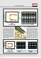
Figure 1 shows the typical frequency
characteristics of phase and im pe-
d ance for CE R A LO CK
®
.
CE R A LO CK
®
is ind uctiv e in the fre-
quency range b etween the resonant
frequency (f
r
) of the m inim um im pe-
d ance v alue and the anti-resonant
frequency (f
a
) of the m ax im um
im ped ance v alue. O utsid e these
ranges it is capacitiv e.
W hen using CE R A LO CK
®
to construct
an oscillator circuit, the ind uctiv e
characteristics b etween f
r
and f
a
are
utiliz ed instead of L in the LC oscilla-
tor circuit.
Figure 2 shows the equiv alent circuit
of either CE R A LO CK
®
or quartz crys-
tal resonators. T he circuit is a series-
parallel resonator circuit that com -
prises the equiv alent resistance R
1
,
the equiv alent ind uctance L
1
, the
equiv alent capacitance C
1
and the
capacitance b etween the electrod es
C
0
. Tab le 1 shows typical v alues for
each circuit elem ent of b oth
CE R A LO CK
®
and quartz crystal re-
sonators.
Figure 3 shows the analogy b etween
the electrical equation of m otion and
the m echanical equation of m otion.
How to design an oscillator
circu it with C E R A L O C K
®
www.murata.com
T h e fo llo wing article d escribes h o w to d esig n a clo ck o scillato r circu it by
u sing C E R A L O C K
®
(reso nato rs), h o w to g et th e o p tim u m circu it co nstant o f
each co m p o nent, and also d iscu sses th e d ifferences between C E R A L O C K
®
and a q u artz cry stal reso nato r.
F ig u re 1 - F req u ency ch aracteristics
o f im p ed ance and p h ase o f C E R A L O C K
®
F ig u re 2 - E q u iv alent circu it o f C E R A L O C K
®
F ig u re 3 - M ech anical and electrical
eq u atio n o f m o tio n