
Datasheet

!
Note
• Please read rating and
!
CAUTION (for storage, operating, rating, soldering, mounting and handling) in this catalog to prevent smoking and/or burning, etc.
• This catalog has only typical specifi cations. Therefore, please approve our product specifi cations or transact the approval sheet for product specifi cations before ordering.
151
GRM SeriesGJM SeriesGMA SeriesGMD SeriesGQM SeriesGRJ SeriesGR3 SeriesKRM SeriesKR3 SeriesLLA SeriesLLL SeriesLLM SeriesLLR Series
!
Caution
Solder Amount
in section
4-3. Correction of Soldered Portion
When sudden heat is applied to the capacitor, distortion caused
by the large temperature difference occurs internally, and can be
the cause of cracks. Capacitors also tend to be affected by
mechanical and thermal stress depending on the board preheating
temperature or the soldering fillet shape, and can be the cause
of cracks. Please refer to "1. PCB Design" or "3. Optimum solder
amount" for the solder amount and the fillet shapes.
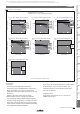
1. Correction with a Soldering Iron
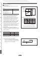
1-1. In order to reduce damage to the capacitor, be sure to
preheat the capacitor and the mounting board. Preheat to
the temperature range shown in Table 3. A hot plate, hot
air type preheater, etc. can be used for preheating.
1-2. After soldering, do not allow the component/PCB to cool
down rapidly.
1-3. Perform the corrections with a soldering iron as quickly
as possible. If the soldering iron is applied too long, there
is a possibility of causing solder leaching on the terminal
electrodes, which will cause deterioration of the adhesive
strength and other problems.
2. Correction with Spot Heater
Compared to local heating with a soldering iron, hot air
heating by a spot heater heats the overall component and
board, therefore, it tends to lessen the thermal shock. In the
case of a high density mounted board, a spot heater can also
prevent concerns of the soldering iron making direct contact
with the component.
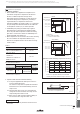
2-1. If the distance from the hot air outlet of the spot heater to
the component is too close, cracks may occur due to
thermal shock. To prevent this problem, follow the
conditions shown in Table 4.
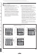
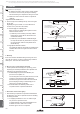
2-2. In order to create an appropriate solder fillet shape, it is
recommended that hot air be applied at the angle shown
in Figure 1.
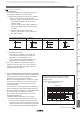
3. Optimum solder amount when re-working with a soldering iron
3-1. In the case of sizes smaller than 0603, (GJM/GQM/GR3/
GRJ/GRM Series, 03/15/18 sizes), the top of the solder
fillet should be lower than
2
/
3
of the thickness of the
component or 0.5mm, whichever is smaller. In the case
of 0805 and larger sizes, (GJM/GQM/GR3/GRJ/
GRM Series, 21/22/31/32/43/55 sizes), the top of the
solder fillet should be lower than
2
/
3
of the thickness of
the component. If the solder amount is excessive, the risk
of cracking is higher during board bending or under any
other stressful condition.
Continued from the preceding page.
Continued on the following page.
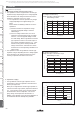
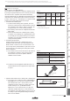
Table 3
GJM/GQM/GR3/
GRJ/GRM Series
03/15/18/21/31 sizes
ΔTV190°C
ΔTV130°C
350°C max.
280°C max.
150°C min.
150°C min.
Air
Air
*Applicable for both Pb-Sn and Lead Free Solder.
Pb-Sn Solder: Sn-37Pb
Lead Free Solder: Sn-3.0Ag-0.5Cu
GRJ/GRM Series
32/43/55 sizes
GQM Series
22 size
Table 4
Hot Air Application Angle
45° *Figure 1
Distance
5mm or more
Hot Air Temperature Nozzle Outlet
400°C max.
Application Time
Less than 10 seconds
(1206 (3216 in mm) size or smaller)
Less than 30 seconds
(1210 (3225 in mm) size or larger)
an Angle of 45°
One-hole Nozzle
[Figure 1]
Part Number
Temperature
Differential
(ΔT)
Atmosphere
Temperature
of Soldering
Iron Tip
Preheating
Temperature
!
Caution