
Datasheet

Only for LCD Backlight Inverter Circuit Specifications and Test Methods
Continued on the following page.
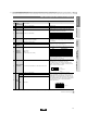
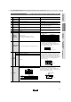
Solder the capacitor to the testing jig (glass epoxy board) shown
in Fig. 2.
Then apply a force in the direction shown in Fig. 3.
The soldering should be done using the reflow method and
should be conducted with care so that the soldering is uniform
and free of defects such as heat shock.
Fig. 3
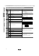
11 Deflection
No marking defects
Fig. 2
Solder the capacitor to the test jig (glass epoxy board).
The capacitor should be subjected to a simple harmonic motion
having a total amplitude of 1.5mm, the frequency being varied
uniformly between the approximate limits of 10 and 55Hz. The
frequency range, from 10 to 55Hz and return to 10Hz, should be
traversed in approximately 1 min. This motion should be applied
for a period of 2 hrs. in each of 3 mutually perpendicular
directions (total of 6 hrs.).10
Vibration
Resistance
Appearance
No defects or abnormalities
Capacitance
Within the specified tolerance
Q 1,000 min.
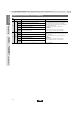
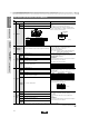
Solder the capacitor to the testing jig (glass epoxy board) shown
in Fig. 1.
Then apply 10N force in the direction of the arrow.
The soldering should be done using the reflow method and
should be conducted with care so that the soldering is uniform
and free of defects such as heat shock.
Fig. 1
9
Adhesive Strength
of Termination
No removal of the terminations or other defect should occur.
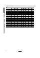
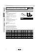
The capacitance measurement should be made at each step
specified in the Table.
8
Capacitance
Temperature
Characteristics
Temp. Coefficient
0T30ppm/D (Temp. Range: W25 to W125D)
0W30, Y72ppm/D (Temp. Range: Y55 to W25D)
7Q 1,000 min.
The capacitance/Q should be measured at a frequency of
1T0.2MHz and a voltage of AC0.5 to 5V(r.m.s.)
6 Capacitance Within the specified tolerance
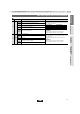
The insulation resistance should be measured with DC500T50V
and within 60T5 sec. of charging.
5
Insulation Resistance
(I.R.)
More than 10,000MΩ
No failure should be observed when DC4095V is applied
between the terminations for 1 to 5 sec., provided the charge/
discharge current is less than 50mA.
4 Dielectric Strength No defects or abnormalities
Using calipers and micrometers3 Dimensions Within the specified dimension
Visual inspection2 Appearance No defects or abnormalities
Y1
Operating
Temperature Range
Y55 to W125D
No. Test MethodSpecificationsItem
Step Temperature (D)
25T2
Min. Operating Temp.T3
25T2
Max. Operating Temp.T2
25T2
1
2
3
4
5
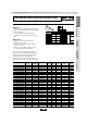
LZW
(mm) a
Dimension (mm)
3.5
b
7.0
c
2.4
d
1.04.5Z2.0
10N, 10T1s
Glass Epoxy Board
Solder resist
Cu
Glass Epoxy Board
b
a
c
100
40
φ4.5
t : 1.6
d
Capacitance meter
Flexure=1
20
50
R230
45 45
(in mm)
Pressurizing
speed: 1.0mm/s
Pressurize
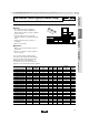
GRM/DC3.15kV Series Specifications and Test Methods
177
!Note
• Please read rating and !CAUTION (for storage, operating, rating, soldering, mounting and handling) in this catalog to prevent smoking and/or burning, etc.
• This catalog has only typical specifications because there is no space for detailed specifications. Therefore, please approve our product specifications or transact the approval sheet for product specifications before ordering.
For General Purpose
GRM/GRJ Series
Only for Applications
GRM/DC3.15kV Series
AC250V Type
GA2 Series
Safety Standard
Certified GA3 Series
Product Information
• This PDF catalog is downloaded from the website of Murata Manufacturing co., ltd. Therefore, it’s specifications are subject to change or our products in it may be discontinued without advance notice. Please check with our
sales representatives or product engineers before ordering.
• This PDF catalog has only typical specifications because there is no space for detailed specifications. Therefore, please approve our product specifications or transact the approval sheet for product specifications before ordering.
!Note
C02E.pdf
10.12.20