
Datasheet


4. Reflow Soldering
When components are exposed to sudden heat, their
mechanical strength can be decreased due to the
extreme temperature changes which can cause flexing
and result in internal mechanical damage, which will
cause the parts to fail. In order to prevent mechanical
damage, preheating is required for both the components
and the PCB board. Preheating conditions are shown in
Table 1. It is required to keep the temperature differential
between the soldering and the components surface (∆T)
as small as possible.
Solderability of Tin plating termination chips might be
deteriorated when low temperature soldering profile
where peak solder temperature is below the Tin melting
point is used. Please confirm the solderability of Tin
plating termination chips before use.
When components are immersed in solvent after
mounting, be sure to maintain the temperature difference
(∆T) between the component and solvent within the
range shown in the Table 1.
G--18/21/31
G--32/42/43/52/55
∆TV190D
∆TV130D
Part Number
Temperature Differential
Table 1
Recommended Conditions
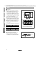
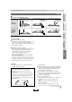
[Standard Conditions for Reflow Soldering]
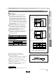
[Allowable Soldering Temperature and Time]
In the case of repeated soldering, the accumulated
soldering time must be within the range shown above.
Soldering Time (sec.)
260
270
250
240
230
0306090
Soldering Temperature (D)
Inverting the PCB
Make sure not to impose an abnormal mechanical shock on
the PCB.
Continued from the preceding page.
Peak Temperature
Atmosphere
Pb-Sn Solder
Infrared Reflow
230-250°C
Air
Vapor Reflow
230-240°C
Air
Lead Free Solder
240-260°C
Air or N
2
Infrared Reflow
Vapor Reflow
60-120 seconds 30-60 seconds
∆T
Gradual
Cooling
Soldering
Preheating
200°C
170°C
150°C
130°C
Time
Temperature (D)
Peak Temperature
60-120 seconds 20 seconds max.
∆T
Gradual
Cooling
Soldering
Preheating
170°C
150°C
130°C
Time
Temperature (D)
Peak Temperature
Pb-Sn Solder: Sn-37Pb
Lead Free Solder: Sn-3.0Ag-0.5Cu
Continued on the following page.
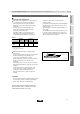
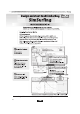
Optimum Solder Amount for Reflow Soldering
Overly thick application of solder paste results in
excessive solder fillet height.
This makes the chip more susceptible to mechanical and
thermal stress on the board and may cause cracked
chips.
Too little solder paste results in a lack of adhesive
strength on the outer electrode, which may result in chips
breaking loose from the PCB.
Make sure the solder has been applied smoothly to the
end surface to a height of 0.2mm min.
[Optimum Solder Amount for Reflow Soldering]
0.2mm min.
in section
!Caution
211
!Note
• Please read rating and !CAUTION (for storage, operating, rating, soldering, mounting and handling) in this catalog to prevent smoking and/or burning, etc.
• This catalog has only typical specifications because there is no space for detailed specifications. Therefore, please approve our product specifications or transact the approval sheet for product specifications before ordering.
For General Purpose
GRM/GRJ Series
Only for ApplicationsAC250V Type
GA2 Series
Safety Standard
Certified GA3 Series
Product Information
!Caution
• This PDF catalog is downloaded from the website of Murata Manufacturing co., ltd. Therefore, it’s specifications are subject to change or our products in it may be discontinued without advance notice. Please check with our
sales representatives or product engineers before ordering.
• This PDF catalog has only typical specifications because there is no space for detailed specifications. Therefore, please approve our product specifications or transact the approval sheet for product specifications before ordering.
!Note
C02E.pdf
10.12.20