
Datasheet

Continued on the following page.
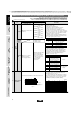
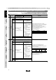
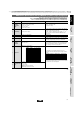
Measuring Frequency
Nominal Capacitance
1±0.1kHz
1±0.1kHz
120±24Hz
1±0.1kHz
Measuring Voltage
1.0±0.2Vrms
0.5±0.1Vrms
0.5±0.1Vrms
0.5±0.1Vrms
CV10µF (10V min.)*
CV10µF (6.3V max.)
CG10µF
*For items in Table1
8
Dissipation Factor
(D.F.)
B1, B3, R1, *R6, *R7, C7, C8, E7, D7: 0.1 max.
C6: 0.125 max.
D8: 0.15 max.
F1, F5: 0.2 max.
*GRM31CR71E106: 0.125 max.
GRM31CR6 0J/0G 107: 0.15 max.
The capacitance/D.F. should be measured at reference
temperature at the measuring frequency and voltage shown in
the table.
GRM188C80E106:
Perform a heat treatment at 150+0/-10°C for one hour and then
set for 24±2 hours at room temperature.
7 Capacitance
Within the specified tolerance
*Table 1
The insulation resistance should be measured with a DC voltage
not exceeding the rated voltage at reference temperature and
75%RH max. and within 1 minutes of charging, provided the
charge/discharge current is less than 50mA.
6
Insulation
Resistance
More than 50Ω · F
No failure should be observed when 250% of the rated voltage
is applied between the terminations for 1 to 5 seconds,
provided the charge/discharge current is less than 50mA.
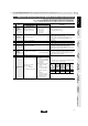
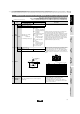
5 Dielectric Strength No defects or abnormalities
Using calipers (GRM02 size is based on Microscope)4 Dimensions Within the specified dimensions
Visual inspection3 Appearance No defects or abnormalities
The rated voltage is defined as the maximum voltage that may
be applied continuously to the capacitor.
When AC voltage is superimposed on DC voltage, V
P-P
or V
O-P
,
whichever is larger, should be maintained within the rated
voltage range.
2 Rated Voltage See the previous pages.
Reference temperature: 25°C
(B1, B3, R1, F1: 20°C)
1
Operating
Temperature
Range
B1, B3, F1: –25 to +85°C
R1, R7, C7, D7, E7: –55 to +125°C
C6, R6: –55 to +85°C
F5: –30 to +85°C
C8, D8: –55 to +105°C,
No. Test MethodSpecificationsItem
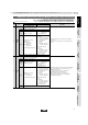
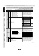
GRM Series Specifications and Test Methods (2) (Note 1)-Typical Inspection
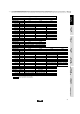
GRM022 B3/R6 1A 681 to 103
GRM155 B3/R6 1A 124 to 105
GRM185 B3/R6 1C/1A 105
GRM185 C8/D7 1A 105
GRM188 B3/R6 1C/1A 225
GRM188 R7/C8 1A 225
GRM188 B3/R6 1A 335
GRM219 B3/R6 1C/1A 475
GRM219 C8 1A 475
GRM219 B3/R6 1A 106
GRM21B B3/R6 1C/1A 106
GRM21B R7/C8 1A 106
GRM319 B3/R6 1C/1A 106
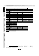
GRM Series Specifications and Test Methods (2) (Note 1)-Typical Inspection
57
!Note
• Please read rating and !CAUTION (for storage, operating, rating, soldering, mounting and handling) in this catalog to prevent smoking and/or burning, etc.
• This catalog has only typical specifications because there is no space for detailed specifications. Therefore, please approve our product specifications or transact the approval sheet for product specifications before ordering.
(Note 1) These Specifications and Test Methods indicate typical inspection.
Please refer to individual specifications (our product specifications or the approval sheet).
When no "*" is added in PNs table, please refer to GRM Series Specifications and Test Methods (1).
When "*" is added in PNs table, please refer to GRM Series Specifications and Test Methods (2).
For General
GRM Series
Array
GNM Series
Low ESL
LLp Series
High-Q
GJM Series
High Frequency
GQM Series
Monolithic Microchip
GMA Series
For Bonding
GMD Series
Product Information
• This PDF catalog is downloaded from the website of Murata Manufacturing co., ltd. Therefore, it’s specifications are subject to change or our products in it may be discontinued without advance notice. Please check with our
sales representatives or product engineers before ordering.
• This PDF catalog has only typical specifications because there is no space for detailed specifications. Therefore, please approve our product specifications or transact the approval sheet for product specifications before ordering.
!Note
C02E.pdf
10.12.20