
Datasheet

Continued from the preceding page.
Fix the capacitor to the supporting jig in the same manner and
under the same conditions as (10).
Perform the five cycles according to the four heat treatments
shown in the following table.
Set for 24±2 hours at room temperature, then measure.
•Initial measurement for high dielectric constant type
Perform a heat treatment at 150+0/–10°C for one hour and
then set at room temperature for 24±2 hours.
Perform the initial measurement.
GRM188R60J106 only Measurement after test Perform a heat
treatment and then let sit for 24±2 hours at room temperature,
then measure.
15
Temperature
Sudden
Change
Appearance
No defects or abnormalities
Dielectric
Strength
No defects
I.R. More than 50Ω · F
D.F.
B1, B3, R1, *R6, *R7, C7, C8, E7, D7: 0.1 max.
C6: 0.125 max.
D8: 0.15 max.
F1, F5: 0.2 max.
*GRM31CR71E106: 0.125 max.
GRM31CR6 0J/0G 107: 0.15 max.
Capacitance
Change
B1, B3, R1, R6, R7, C6, C7, C8, D7, D8: Within ±7.5%
E7: Within ±30%
F1, F5: Within ±20%
Preheat the capacitor at 120 to 150°C for 1 minute.
Immerse the capacitor in a eutectic solder* or Sn-3.0Ag-0.5Cu
solder solution at 270±5°C for 10±0.5 seconds. Set at room
temperature for 24±2 hours, then measure.
*Do not apply to GRM02.
•Initial measurement for high dielectric constant type
Perform a heat treatment at 150+0/–10°C for one hour and
then set at room temperature for 24±2 hours.
Perform the initial measurement.
*Preheating for GRM32/43/55
14
Resistance
to
Soldering
Heat
Appearance
No defects or abnormalities
Dielectric
Strength
No defects
I.R. More than 50Ω · F
D.F.
B1, B3, R1, *R6, *R7, C7, C8, E7, D7: 0.1 max.
C6: 0.125 max.
D8: 0.15 max.
F1, F5: 0.2 max.
*GRM31CR71E106: 0.125 max.
GRM31CR6 0J/0G 107: 0.15 max.
Capacitance
Change
B1, B3, R1, *R6, R7, C6, C7, *C8, E7, D7, D8: Within ±7.5%
F1, F5: Within ±20%
*
GRM188R6 0J/0G 106, GRM188C8 0E/0G 106, GRM219R60G226:
Within ±12.5%
GRM155R60G475,
GRM155R60E106, GRM188R60G226:
Within ±15%
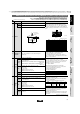
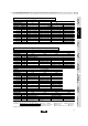
GRM Series Specifications and Test Methods (2) (Note 1)-Typical Inspection
TemperatureStep
100 to 120°C
170 to 200°C
Time
1 min.
1 min.
1
2
1Step
Min.
Operating
Temp. +0/–3
30±3
2
Room
Temp.
2 to 3
3
Max.
Operating
Temp. +3/–0
30±3
4
Room
Temp.
2 to 3
Temp. (°C)
Time (min.)
Continued on the following page.
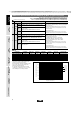
Immerse the capacitor in a solution of ethanol (JIS-K-8101) and
rosin (JIS-K-5902) (25% rosin in weight proportion).
Preheat at 80 to 120°C for 10 to 30 seconds.
After preheating, immerse in a eutectic solder solution for
2±0.5 seconds at 230±5°C or Sn-3.0Ag-0.5Cu solder solution
for 2±0.5 seconds at 245±5°C.
13
Solderability of
Termination
75% of the terminations is to be soldered evenly and
continuously.
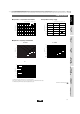
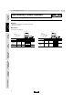
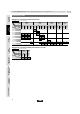
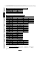
Solder the capacitor on the test jig (glass epoxy board) shown
in Fig. 2a using a eutectic solder. Then apply a force in the
direction shown in Fig. 3a for 5±1 sec. The soldering should be
done by the reflow method and should be conducted with care
so that the soldering is uniform and free of defects such as heat
shock.
Fig. 2a
(in mm)
12 Deflection
Appearance
No marking defects
Capacitance
Change
Within ±10%
Fig.3a
aType
0.2
0.3
0.4
1.0
1.2
2.2
2.2
3.5
4.5
b
0.56
0.9
1.5
3.0
4.0
5.0
5.0
7.0
8.0
c
0.23
0.3
0.5
1.2
1.65
2.0
2.9
3.7
5.6
GRM02
GRM03
GRM15
GRM18
GRM21
GRM31
GRM32
GRM43
GRM55
Capacitance meter
Flexure : V1
20
50
R230
Pressurizing
speed: 1.0mm/sec.
Pressurize
45 45
b
a
c
100
t: 1.6mm
(GRM02/03/15: t: 0.8mm)
40
ø4.5
No. Test MethodSpecificationsItem
GRM Series Specifications and Test Methods (2) (Note 1)-Typical Inspection
59
!Note
• Please read rating and !CAUTION (for storage, operating, rating, soldering, mounting and handling) in this catalog to prevent smoking and/or burning, etc.
• This catalog has only typical specifications because there is no space for detailed specifications. Therefore, please approve our product specifications or transact the approval sheet for product specifications before ordering.
(Note 1) These Specifications and Test Methods indicate typical inspection.
Please refer to individual specifications (our product specifications or the approval sheet).
When no "*" is added in PNs table, please refer to GRM Series Specifications and Test Methods (1).
When "*" is added in PNs table, please refer to GRM Series Specifications and Test Methods (2).
For General
GRM Series
Array
GNM Series
Low ESL
LLp Series
High-Q
GJM Series
High Frequency
GQM Series
Monolithic Microchip
GMA Series
For Bonding
GMD Series
Product Information
• This PDF catalog is downloaded from the website of Murata Manufacturing co., ltd. Therefore, it’s specifications are subject to change or our products in it may be discontinued without advance notice. Please check with our
sales representatives or product engineers before ordering.
• This PDF catalog has only typical specifications because there is no space for detailed specifications. Therefore, please approve our product specifications or transact the approval sheet for product specifications before ordering.
!Note
C02E.pdf
10.12.20