
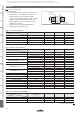
Datasheet


!
Note
• Please read rating and
!
CAUTION (for storage, operating, rating, soldering, mounting and handling) in this catalog to prevent smoking and/or burning, etc.
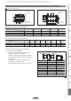
• This catalog has only typical specifi cations. Therefore, please approve our product specifi cations or transact the approval sheet for product specifi cations before ordering.
157
GRM SeriesGJM SeriesGMA SeriesGMD SeriesGQM SeriesGRJ SeriesGR3 SeriesKRM SeriesKR3 SeriesLLA SeriesLLL SeriesLLM SeriesLLR SeriesNotice
1. Operating Temperature
1. The operating temperature limit depends on the capacitor.
1-1. Do not apply temperatures exceeding the upper
operating temperature.
It is necessary to select a capacitor with a suitable
rated temperature that will cover the operating
temperature range.
It is also necessary to consider the temperature
distribution in equipment and the seasonal
temperature variable factor.
1-2. Consider the self-heating factor of the capacitor.
The surface temperature of the capacitor shall be
the upper operating temperature or less when
including the self-heating factors.
2. Atmosphere Surroundings (gaseous and liquid)
1. Restriction on the operating environment of capacitors.
1-1. Capacitors, when used in the above, unsuitable,
operating environments may deteriorate due to
the corrosion of the terminations and the
penetration of moisture into the capacitor.
1-2. The same phenomenon as the above may occur
when the electrodes or terminals of the capacitor
are subject to moisture condensation.
1-3. The deterioration of characteristics and insulation
resistance due to the oxidization or corrosion of
terminal electrodes may result in breakdown when
the capacitor is exposed to corrosive or volatile
gases or solvents for long periods of time.
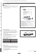
3. Piezo-electric Phenomenon
1. When using high dielectric constant type capacitors in
AC or pulse circuits, the capacitor itself vibrates at
specific frequencies and noise may be generated.
Moreover, when the mechanical vibration or shock is
added to the capacitor, noise may occur.
c Rating
c Soldering and Mounting
1. PCB Design
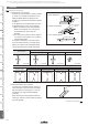
1. Notice for Pattern Forms
1-1. Unlike leaded components, chip components are
susceptible to flexing stresses since they are
mounted directly on the substrate.
They are also more sensitive to mechanical and
thermal stresses than leaded components.
Excess solder fillet height can multiply these stresses
and cause chip cracking. When designing substrates,
take land patterns and dimensions into consideration
to eliminate the possibility of excess solder fillet
height.
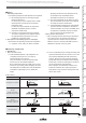
1-2. There is a possibility of chip cracking caused by PCB
expansion/contraction with heat, because stress on a
chip is different depending on PCB material and
structure. When the thermal expansion coefficient
greatly differs between the board used for mounting
and the chip, it will cause cracking of the chip due to
the thermal expansion and contraction.
When capacitors are mounted on a fluorine resin
printed circuit board or on a single-layered glass
epoxy board, it may also cause cracking of the chip
for the same reason.
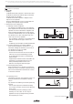
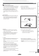
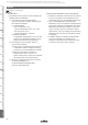
Chassis
Solder (ground)
Electrode Pattern
Solder Resist
Solder Resist
Solder Resist
Lead Wire
Soldering Iron
Lead Wire
Solder Resist
Pattern Forms
Placing Close to Chassis
Placing
of Chip Components
and Leaded Components
Placing
of Leaded Components
after Chip Component
Lateral Mounting
Prohibited Correct
Continued on the following page.
Notice