
Datasheet

!
Note
• Please read rating and
!
CAUTION (for storage, operating, rating, soldering, mounting and handling) in this catalog to prevent smoking and/or burning, etc.
• This catalog has only typical specifi cations. Therefore, please approve our product specifi cations or transact the approval sheet for product specifi cations before ordering.
161
GRM SeriesGJM SeriesGMA SeriesGMD SeriesGQM SeriesGRJ SeriesGR3 SeriesKRM SeriesKR3 SeriesLLA SeriesLLL SeriesLLM SeriesLLR SeriesNotice
Continued from the preceding page.
1. A crack may be caused in the capacitor due to the stress
of the thermal contraction of the resin during curing
process.
The stress is affected by the amount of resin and curing
contraction.
Select a resin with low curing contraction.
The difference in the thermal expansion coefficient
between a coating resin or a molding resin and the
capacitor may cause the destruction and deterioration of
the capacitor such as a crack or peeling, and lead to the
deterioration of insulation resistance or dielectric
breakdown.
Select a resin for which the thermal expansion coefficient
is as close to that of the capacitor as possible.
A silicone resin can be used as an under-coating to buffer
against the stress.
2. Select a resin that is less hygroscopic.
Using hygroscopic resins under high humidity conditions
may cause the deterioration of the insulation resistance of
a capacitor.
An epoxy resin can be used as a less hygroscopic resin.
7. Coating
1. Please evaluate the capacitor using actual cleaning
equipment and conditions to confirm the quality, and
select the solvent for cleaning.
2. Unsuitable cleaning solvent may leave residual flux or
other foreign substances, causing deterioration of
electrical characteristics and the reliability of the
capacitors.
3. Select the proper cleaning conditions.
3-1. Improper cleaning conditions (excessive or
insufficient) may result in deterioration of the
performance of the capacitors.
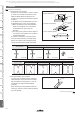
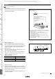
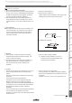
6. Washing
o Set temperature and time to ensure that leaching of the
outer electrode does not exceed 25% of the chip end
area as a single chip (full length of the edge A-B-C-D
shown at right) and 25% of the length A-B shown as
mounted on substrate.
[As a Single Chip]
[As Mounted on Substrate]
5. Flow Soldering
A
B
C
D
Outer Electrode
A
B
4. Flux for Reflow and Flow Soldering
1. An excessive amount of flux generates a large quantity of
flux gas, which can cause a deterioration of solder ability,
so apply flux thinly and evenly throughout. (A foaming
system is generally used for flow soldering.)
2. Flux containing too high a percentage of halide may
cause corrosion of the outer electrodes unless there is
sufficient cleaning. Use flux with a halide content of 0.1%
max.
3. Do not use strong acidic flux.
4. Do not use water-soluble flux.*
(*Water-soluble flux can be defined as non-rosin type flux
including wash-type flux and non-wash-type flux.)
Continued on the following page.
Notice