
Datasheet


PV12/PV37/PV23/PV22/PV36 Series Notice
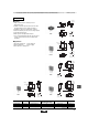
72
8
!Note
• Please read rating and !CAUTION (for storage, operating, rating, soldering, mounting and handling) in this catalog to prevent smoking and/or burning, etc.
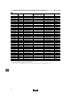
• This catalog has only typical specifications because there is no space for detailed specifications. Therefore, please approve our product specifications or transact the approval sheet for product specifications before ordering.
■ Notice (Handling)
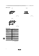
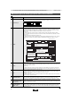
1. Use suitable screwdrivers that fit comfortably in
driver slot. We recommend the screwdrivers below.
* Recommended screwdriver for manual adjustment
ENGINEER INC. : DA-40
(Murata P/N : KMDR180)
We can supply the screwdrivers above.
If you place order, please specify the Murata P/N.
2. Don't apply more than 9.8N (Ref.; 1kgf) of twist
and stress after mounting onto PCB to prevent
contact intermittence. If excessive force is
applied, the trimmer potentiometer may not
function.
3. When adjusting with an adjustment tool, the applied
force to the adjustment screw should not exceed
4.9N (Ref.; 500gf). If excessive force is applied,
the trimmer potentiometer may not function due to
damage.
4. When using a lock paint to fix slot position,
please use adhesive resin without chlorine or
sulfur (Three-bond "1401 series").
■ Notice (Other)
1. Please make sure that your product has been
evaluated and confirmed against your
specifications when our product is mounted to your
product.
2. Murata cannot guarantee trimmer potentiometer
integrity when used under conditions other than
those specified in this document.
Please read rating and !CAUTION (for storage, operating, rating, soldering, mounting and handling) in this PDF catalog to prevent smoking and/or burning, etc.
This catalog has only typical specifications. Therefore, you are requested to approve our product specifications or to transact the approval sheet for product specifications before ordering.
!Note
R50E13.pdf 04.6.11