Heavy Duty Auto Feeding Screwdriving Tool Instruction manual Table of contents Safety precautions Parts designation Specifications Assembling VISLIDER Loading VISROPE Driving screws Maintenance and inspection 1 1 1 2 3-5 5-6 7 (with warranty card)
Safety precautions WARNING Denotes risk of personal injury, loss of life or damage to the tool In case of nonobservance of the instructions in this manual. Before use, be sure to carefully read the instructions. Read the related Drill instruction manual, too. Be sure to wear protective goggles during work. Be sure to wear a dust-proof mask during work. Depending on the work environment, wear ear protectors, hardhat, working shoes, and other safety gear.
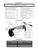
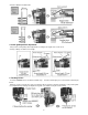
Assembling VISLIDER 1. Assembly and fitting of rod handle Remove the hexagon fitting bolt and the washer from the handle rod. To the handle rod, fit the handle bar, the washer and the hexagon bolt in this order. Tighten the hexagon fitting bolt using the 13mm spanner. Mount the assembled rod handle on the rear of the main body. Tighten the two fitting screws using the 6mm wrench. 2.
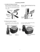
Loading VISROPE 1.Setting VISROPE Set the VISROPE to the magazine as shown below. (Remove the rubber band from the VISROPE.) Open the magazine cover while pulling the magazine lever. 2. Switching magazine inner lid Lift the inner lid while holding the inner lid stopper on the magazine cover. orientation corresponding to the screw length. Insert the inner lid until it snaps in the 3. VISROPE types and stopper block adjustment Two types are available in the VISROPE for VL71-FLR, 30mm type and 22mm type.
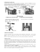
* Factory setting is for 30mm type. 4. Screw guide position adjustment Carry out the screw guide position adjustment according to the length of the screws used. * Factory setting is for 45mm screw length. 5. Feeding screws Insert the VISROPE into the feeder block until it stops. Push the main body by no less than 30mm, and then pull it back. When the screw is not fed to the center even after the above step was repeated several times, carry out the guide cover adjustment by referring to 6.
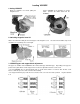
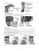
. Adjustment of guide cover Improper guide cover play can affect screw feeding or screw driving. Any time the VISROPE was replaced, make sure to check the guide cover play and adjust it to the adequate level. To adjust the play, first loosen the hexagon nut using the 7mm spanner and then adjust the cap screw using the 3mm wrench. After this, tighten the hexagon nut using the 7mm spanner to fix the cap screw. Driving screws 1. Adjustment of rod handle length 2.
5. Removal of VISROPE To remove the VISROPE, pull out the VISROPE while the guide cover and the grip finger are open. * Push the main body 5mm or so to facilitate withdrawal of the VISROPE. 6. Bit replacement To remove the bit, first pick up the bit as much as possible while pulling the sleeve. Then, while pulling back (pressing down) the top end, pull out the whole bit. To mount the bit, insert the bit while pulling back (pressing down) the top end.
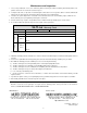
Maintenance and inspection 1. The tool may malfunction if it is used continuously without removing the adhered sawdust, plasterboard particles, iron powder or dusts. Be sure to clean the tool after every use. 2. To wipe the unit clean, use dry cloth or neutral detergent-soaked cloth. Do not use gasoline, thinner or the like, which would damage the unit. Never wash the unit in water, which would get it rusty or malfunctioning. 3. The bit of the specific adaptor kit is consumable.