CENTURION Configurable Controller Installation and Operations Manual TM TM CE-05171N Effective 05-13-05 Section 50 (00-02-0590) CE-05171N page 1 of 44
1.0 Warning and Limited Warranty WARNING! FW MURPHY has made efforts to ensure the reliability of the Centurion Controller and to recommend safe usage practices in system applications. Please note that in any application, operation and controller failures can occur. These failures may result in full control outputs or other outputs which may cause damage to or unsafe conditions in the equipment or process connected to the Centurion Controller.
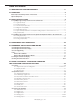
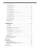
Table of Contents 1.0 WARNING AND LIMITED WARRANTY..................................................................................2 2.0 OVERVIEW .........................................................................................................................................5 Basic Components and Key Features of the C3 Series .....................................................................................5 Optional Components.....................................................................
6.3.6 Thermocouple Input................................................................................................................26 6.3.7 General Timer Setup............................................................................................................... 27 6.3.8 Maintenance Timer Setup....................................................................................................... 28 6.3.9 Set points Setup...........................................................................
2.0 Overview The Centurion configurable controller is a control and monitoring system expressly designed to meet the requirements of three specific kinds of applications: Screw and Reciprocating Compressors, and Pumps. To that end, it is able to satisfy the particular needs and inevitable variations that exist in real world applications because the Centurion controller is enormously flexible and configurable within fixed parameters.
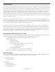
3.0 Input/Output Types 3.1 Input/Output Types and Specifications for the Centurion C3-1 CAN J1939 Communications (RS4232, 485, USB) Optional Digital Outputs Analog Outputs (DO) See 3.1.5 (AO) See 3.1.6 Magnetic Pickup (MPU) See 3.1.4 C3-1 Thermocouple Inputs (TC) See 3.1.3 Analog Inputs (AI) See 3.1.2 Digital Inputs (DI) See 3.1.1 3.1.1 Digital Inputs (DI) Number of Devices: 32 Device Types: Discrete Input, Normally Open (N/O) or Normally Closed (N/C), active high/active low, non-incendive.
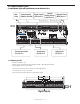
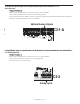
3.1.2 Analog Inputs (AI) Number of Devices: 12 Device Types: Analog Input, (4 to 20) mA or (0 to 5) V, 10 bit hardware. There is one screw terminal connector for each analog input. Terminals 18 to 29 are AI terminals. C3-1 Analog Inputs 3.1.3 Thermocouple Inputs (TC) Number of Devices: 8 Device Types: Thermocouple Input, Type J or K, 12 bit hardware. Open Thermocouple Detection: Drives terminal reading high (max of scale). Automatic Cold Junction Compensation is built-in.
3.1.4 Magnetic Pickup (MPU) Number of Devices: 1 Device Types: Magnetic Pickup or MPU, (5 to 120) Vrms, (30 to 10k) Hz. There are two screw terminal connectors for the Magnetic Pickup . Terminals 64 and 65 are MPU terminals. Magnetic Pickup C3-1 3.1.
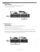
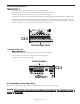
3.1.6 Types and Specifications for the Optional Analog Output on the Centurion C3-1 -A Analog Outputs (AO) Number of Devices: 2 Device Types: Analog Output, (4 to 20) mA or (0-5)V, 16 bit hardware There are two screw terminal connectors for each analog output. The AO optional module is added to the C3-1 at the factory inside the DIN enclosure. While these terminals are present on all models the feature may not be installed. Optional Analog Outputs C3-1-A 3.
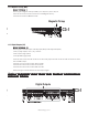
3.2.2 Thermocouple Inputs (TC) Number of Devices: 8 Device Types: Thermocouple Input, Type J or K, 12 bit hardware Open Thermocouple Detection: Drives channel reading high (max of scale). There are two screw terminal connectors for each thermocouple input. Terminals 109 to 124 are TC channels where White or Yellow indicate positive inputs and Red indicates negative inputs. An additional terminal connector is provided, identified as SHD, which isolates thermocouple shields.
5.0 Hardware Installation and Wiring 5.1 Mounting the Centurion Controller The Centurion can be mounted vertically or horizontally on a standard DIN rail. Three clamp type feet along the bottom of the controller attach to the DIN rail, however, rail stops are recommended to prevent sliding. 2-1/2 in. (64 mm) MOUNTING BRACKET DETAIL 13-1/8 in. (333 mm) DIN Type Mounting Rail 4-7/8 in. (125 mm) C3-1 Mounting Bracket C3-1 To Panel 5.
5.
5.
5.
6.0 Using the C3-3 Display to View and Configure the Centurion Controller Settings The Murphy C3-3 Display module is a highly integrated operator interface specially programmed to complement and support Centurion controller. The primary purpose of C3-3 Display is to display operational and configuration parameters and provide access to modify the configuration parameters stored in the Centurion controller. 6.
HOME HOME Operating Status Screen Allows the user to get to the first line of the current screen, or if pressed again, to get to the default operating status screen. Set Up Screen Allows the user to get to the first line of the current screen Edit Screen No associated action. ESC/ACK ESC ACK Operating Status Screen Acknowledge the active message/alarm that is currently displayed in the Alarm Banner. Acknowledges all active messages and alarms displayed in the Active Alarm Screen.
RUN/STOP RUN STOP Operating Status Screen Initiate or cancel a start sequence. Set Up Screen No associated action in either Shutdown mode, or Remote mode on standby. Initiate stop sequence when held for two seconds, if equipment is running. Edit Screen No associated action. ARROW UP Operating Status Screen Scroll up one line. Automatically repeats if held down continuously until reaching the first line. For history screens, scrolls up one history (for example: Shutdown or Event).
ARROW RIGHT Operating Status Screen Display next screen. Automatically repeats if held down continuously until reaching the final screen. Set Up Screen Display next screen. This key has no action when in a sub-menu. Edit Screen Move the cursor to the next digit. TEST TEST Operating Status Screen Enter test mode and start test timer. This is not applicable in Shutdown mode. Set Up Screen No associated action. Edit Screen No associated action.
6.1.2 Display Context The graphic LCD displays are organized around operating status screens and setup screens. The actual number of status screens will be related to the total number of end devices configured for the controller. In either screen set, ten (10) lines are visible at a time; with up and down arrow characters indicating more lines are available on the page. Also, for both screen sets, navigation between screens is accomplished by pressing the left or right arrow keys.
6.2 Operational Screens In addition to the set up screens reviewed in Section 7.3, the C3-3 Display offers a number of operational displays. On the Operating Status screens, the two bottom lines display the state, hours, mode and active timer status. This information is key to understanding the “status” of the controller. Mode refers to the Operating Mode of the controller and can be LOCAL or REMOTE.
6.2.4. Shutdown History Screen C TM ▼ SHUTDOWN HISTORY 1/3 ___________________________________ PANEL ESD 00059:16:09 LOW SUCT PRESS 00059:15:11 OVERCRANK 00054:04:40 The history of the last twenty shutdowns is displayed on this screen, with the most recent at the top of the list and the oldest at the bottom. Each event is displayed with the shutdown label on one line and the hour meter reading on the following line.
6.2.5 Gage Display C TM OIL PRS WTR TEMP 42 PSI BATTERY 145 °F ENG SPEED VDC 13.7 1250 RPM ___________________________________ REMOTE WARMUP This is an example of a custom gage display. Configured software orders the data as needed. This display provides larger characters for easier viewing as well as a means to prominently display items of interest. Unacknowledged alarms will overwrite the bottom half of the lower two gage boxes.
6.3 Setup Screens and Menus 6.3.1 Password Screen C Some settings are password protected, including the setup screens. This is the first screen seen when the SETUP/ENTER key is pressed. TM The password need only be entered once during any editing session. The password will reset when the editing session is exited, or is timed-out due to keyboard inactivity.
6.3.2 Digital Input C TM ▼ DIGITAL INPUTS ___________________________________ DIGITAL INPUT 1 DIGITAL INPUT 2 DIGITAL INPUT 3 DIGITAL INPUT 4 DIGITAL INPUT 5 ___________________________________ D_IN_01 N/0 ___________________________________ Digital Input: For up to 32 configured Digital Input devices, the user may select whether an input is normally open (N/O), or normally closed (N/C).
C TM ▼ ANALOG INPUT 1 SETUP ___________________________________ MOVING AVERAGE SAMPLES RAW COUNT OFFSET RAW COUNT SPAN MINIMUM MAXIMUM ___________________________________ (1,2,OR 4) 1 ___________________________________ ▼ ▼▲ ENTER-EDIT ESC EXIT THIS MENU Analog Input 1 Setup Screen C TM ▼ ANALOG INPUT 1 SETUP ___________________________________ MOVING AVERAGE SAMPLES RAW COUNT OFFSET RAW COUNT SPAN MINIMUM MAXIMUM ___________________________________ (1,2,OR 4) 1 ___________________________________
C TM ▼ ANALOG OUTPUTS 1 SETUP ___________________________________ RAW COUNT OFFSET RAW COUNT SPAN MINIMUM MAXIMUM ▼ ▼ ▼ ___________________________________ 00000 _ ___________________________________ ▼▲ ENTER-ACCEPT ESC-CANCEL Analog Output 1 Setup Screen 1 6.3.
6.3.7 General Timer Setup C User may edit all general purpose timers. Generally, global timers affect engine operation. They also help define an event. TM ▼ ___________________________________ GENERAL TIMER SETUP B1 TIMER B2 TIMER C TIMER S1 TIMER S2 TIMER ___________________________________ (0 - 999) 00060 ___________________________________ ▼ ▼▲ ENTER-EDIT MORE MENU General Timer Setup Screen a) B1: All event types can be associated with, and locked out by, a Bx timer.
6.3.8 Maintenance Timer Setup C TM ▼ MAINTENANCE TIMER SETUP ___________________________________ MAINTENANCE TIMER 1 MAINTENANCE TIMER 2 MAINTENANCE TIMER 3 MAINTENANCE TIMER 4 MAINTENANCE TIMER 5 ___________________________________ The user may access and edit the ten (10) maintenance settings for timer duration. The user may also access and reset all timer duration and time remaining settings.
6.3.9 Set points Setup C TM ▼ SETPOINTS SETUP ___________________________________ SETPOINTS 1-16 SETPOINTS 17-32 SETPOINTS 33-48 SETPOINTS 49-64 SETPOINTS 65-80 ___________________________________ ▼ ▼ ▼ ___________________________________ ▼▲ ENTER-SUBMENU MORE MENUS C Setpoints Setup Screen TM ▼ SETPOINTS SETUP ___________________________________ SETPOINTS 1 SETPOINTS 2 SETPOINTS 3 SETPOINTS 4 SETPOINTS 5 ___________________________________ LO SUCT PRS 0008.
h) Assign value to Decrease Changeover Off Time. (Set fixed off-time for single pulse on direction change for Decrease). For more on Control Output, please refer to the Centurion Configurable Controller Programming Manual. 6.3.
6.3.12 Initial RPM Setup C a) Assign value for Warmup RPM. b) Assign value for Wait to Load RPM. c) Assign value for Run Loaded RPM. d) Assign value for Cooldown RPM. TM ▼ INITIAL RPM SETUP ___________________________________ WARMUP RPM WAIT FOR LOAD RPM RUN LOADED RPM COOLDOWN RPM ▼ ___________________________________ 00600 ___________________________________ ▼ ▼ ▼▲ ENTER-EDIT MORE MENUS Initial RPM Setup Screen 6.3.
6.3.14 Lube No Flow Set Up C TM ▼ LUBE NO-FLOW SETUP ___________________________________ NO-FLOW INPUT # 1 NO-FLOW INPUT # 2 NO-FLOW INPUT # 3 NO-FLOW INPUT # 4 NO-FLOW INPUT # 5 ___________________________________ ▼ ▼ ▼ DI_1 NF ___________________________________ ▼▲ ENTER-SUBMENU MORE MENUS C User can view and edit Lube No Flow set up. There are two levels to this menu as there are two possible adjustments per No-Flow input. The user will select an input from the first menu and press Setup/Enter.
C Also, the message “History Cleared” will be displayed until another key is pressed. d) Reset Fault History e) Reset Event History TM ▼ SUPER USER MENU ___________________________________ RESET FAULT HISTORY RESET EVENT HISTORY P1 PU/PD P1 TERMINATION P2 PU/PD ___________________________________ ▼ The P1 and P2 signify Communication Port 1 and Communication Port 2 and are for setting up the RS485 interfaces on the display’s serial ports. PU/PD designates the pull-up and pull-down resistors.
6.3.19 Digital Input Status C The user can see the state of each digital input in a table— whether it is open or closed.
C TM ▼ ANALOG OUTPUT STATUS ___________________________________ ANALOG OUTPUT 1 ANALOG OUTPUT 2 ANALOG OUTPUT 3 ANALOG OUTPUT 4 ANALOG OUTPUT 5 ___________________________________ ▼ AI 1 ENG SPEED 030.
C TM ▼ COMMUNICATION STATUS ___________________________________ MODBUS REGISTER ▼ ___________________________________ REG: 40001 VAL: 00000 ___________________________________ ▲▼ ENTER-EDIT MORE MENUS k) Modbus Requests l) Modbus Responses m) Modbus Exceptions n) Modbus Invalid Response o) Modbus No Response p) Clear Statistics q) Modbus Register ▼ ▼ Communication Status Screen 2 C TM ▼ COMMUNICATION STATUS ___________________________________ MODBUS REGISTER ▼ ________________________________
6.4 Additional Navigational Aids 6.4.1 Function Key C TM FW MURPHY - MVIEW WWW.FWMURPHY.COM SALES@FWMURPHY.COM (918) 317-4100 ___________________________________________________ Fn-EXIT HOME-HELP ACK-ALARMS SCREEN REMOTE MODE COMMANDS: RESET AND RUN/STOP Fn Key Dialog Box Screen Pressing the Function (Fn) key from any screen will display a dialog box on the bottom half of the screen. All available function key commands will be displayed there.
Port 2 (USB) Interface: USB 1.1 Compliant Port capable of emulating RS232 communications via royalty free PC driver. Protocol/Services: Modbus (Slave), Proprietary (Binary) Connection: There is a USB Type B connector (see graphic). Automatic selection of USB is provided when a signal is detected on the USB Type B connector. Port 3 (CAN) Protocol/Services: Proprietary (Binary) Connection: There are three (3) screw terminal connectors for CAN. These are identified as HI, LOW, and SHD.
7.2.3 Downloading Configurations Via MConfigPro Software The Centurion makes it easy for a user to download a configuration through the MConfigPro software. 1. From the Options menu of the MConfigPro software, choose the Options tab to identify the ports that the users PC can detect, and select the appropriate port that the user’s PC will use to communicate with the C3-3 Display or Centurion controller. Set the individual port parameters. 2.
7.2.6 Error Messages There may be occasion when an invalid configuration error might display because the configuration between the Centurion controller and its devices are out of synch--that is to say the checksums do not match. In fact, the invalid configuration screen will appear briefly after downloading configurations until comparisons are made. Field testers may decide to ignore the message, if the user knows that the changes are not critical.
7.3 Modbus Protocol The Centurion configurable controller was programmed with the Modbus protocol which is a system is based on a “master” and “slave” relationship. With Modbus protocol, the master and slave are able to continue to communicate with each other through defined messages over a variety of network types. The master initiates the queries or commands, and the slave responds to the query with a message or takes action based on the query.
8.0 Glossary Analog Input Terminals A18 to A29 are analog inputs on the C3-1 Centurion main I/O module. Accepts voltage signals within the range of (0 to 5) VDC or (4 to 20) mA and are compared to controller set points or events. Boot loader Means by which the Centurion controller communicates with C3-3 Display and MConfigPro to receive and transfer new or updated configurations and firmware; and ensure data and configuration synchronization.
9.0 Appendices 9.1 Back Panel LED Description There are a total of seven (7) LED indicators on the back panel, labeled as follows: (Port 1) TX – Turned on while Port 1 is transmitting data. RX – Turned on while Port 1 is receiving data. (Port 2) TX – Turned on while Port 2 is transmitting data. RX – Turned on while Port 2 is receiving data. USB LINK – Turns on while there is a USB connection to a computer.
How To Order Selecting a Centurion Configurable Controller C3 Series Model: 1. Specify one C3-1 Main I/O Module from Table A Table A: C3-1 Main module Options Model Main I/O Module Model: C3-1 Specifications C3-1 no analog outputs C3-1-A two analog outputs 2. Specify one (optional) C3-2 Expansion I/O Module Expansion I/O Module Model: C3-2 (optional) 3.