EVS-2 Electronic Vibration Switch Installation and Operations Manual 00-02-0841 2013-01-14 Section 20
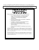
In order to consistently bring you the highest quality, full featured products, we reserve the right to change our specifications and designs at any time. The latest version of this manual can be found at www.fwmurphy.com. Warranty – A limited warranty on materials and workmanship is given with this FW Murphy product. A copy of the warranty may be viewed or printed by going to http://www.fwmurphy.com/warranty. Please read the following information before installing the EVS-2.
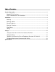
Table of Contents Product Information ...................................................................................................................1 Murphy EVS-2 Overview ..............................................................................................1 EVS-2 Characteristics and Orientation .........................................................................2 Installation .................................................................................................................
THIS PAGE INTENTIONALLY LEFT BLANK
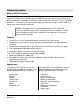
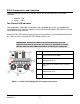
Product Information Murphy EVS-2 Overview The Murphy Electronic Vibration Switch (EVS-2) protects against equipment failure by monitoring velocity-based vibration levels and providing an early warning or shutdown when abnormal vibration is detected. The EVS-2 can be connected to Murphy’s TTD annunciator, Centurion , Centurion PLUS or any third- party controller that accepts a switch input or 420mA signal for increased functionality.
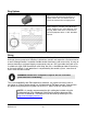
EVS-2 Characteristics and Orientation To prevent damage to the EVS-2 vibration switch, the following vibrations may not be exceeded: Vibration 15 g Shock 150 g Two-Channel LED Indicators Two independent, adjustable level detectors with selectable delay times are equipped with corresponding relays which are typically used for Alarm and Shutdown. Both channels use the same vibration range selection. Red and Yellow LED indicators representing these two channels are illuminated during normal use.
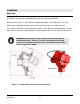
Installation Mounting The Murphy EVS-2 must be mounted and set in accordance with the guidelines in this manual to obtain the desired and specified performance and equipment protection. Mounting occurs via a ½” NPT thread, the tightening torque is hand tight plus 2 to 3 turns. When using a mounting bracket, ensure that mounting surfaces are smooth and flat. Care must also be taken that the mounting surface is not subject to natural vibrations.
Mounting Options The following diagrams illustrate example mounting options for the EVS-2 using a simple pipe plug welded to the machine surface or a bracket with the special adapter provided for drilled and tapped surface mount. NOTE: The special adapter is available for sale. Also note that a hollow pipe close nipple is NOT recommended for installations.
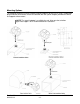
Bracket Proposals Mounting Examples Legend: C=Compressor, E=Engine Compressor Cx (Compressor) = Crankshaft endplay Cy = Main Bearings, Rod Bearings Cz = Main Bearings Section 20 2013-01-14 Engine Ex (Engine) = Crankshaft endplay Ey = Main Bearings Ez = Main Bearings, Detonation, Rod Bearings 00-02-0841 -5-
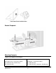
Plug Options High-pressure (non-hollowed), forged steel pipe plug permanently welded to equipment or bracket surface. Be sure weld is clear of threads for maximum thread engagement. Optional Adapter available from FW Murphy: ½” NPT, High-pressure (non-hollowed), steel pipe plug, Male x Male to be used for direct mount to equipment with a ½” NPT threaded pilot hole.
Terminal Assignment The power supply +24 VDC voltage is connected via terminals 1 and 2. NOTE: Minimum voltage acceptable for normal operation is 20-30 VDC. A DC to DC converter can be used for 12V systems. Murphy recommends the Phoenix Contact MINI-PS-12-24DC/24DC/1 or equivalent. Non-latching relay outputs for Channel 1 (K1) and Channel 2 (K2) are present on terminals 3 through 8.
Figure 3 - EVS-2 Hook-up (showing only how to wire Channel 1 {K1}) Section 20 2013-01-14 00-02-0841 -8-
Figure 3 - EVS-2 Hook-up (continued) Section 20 2013-01-14 00-02-0841 -9-
Settings Setting the Set-Point in Inches Per Second (IPS) Peak NOTE: The unit must be set per the application upon installation. Factory Settings: - 1.5 IPS - 1 sec.
Procedure Refer to the monitored machine recommended setting and mounting information and make appropriate adjustments. To adjust the setpoint, open the Murphy EVS-2 cover and follow these steps: Select the appropriate delay settings and ranges using the DIP switches. A. Time delays for each channel are set to either 1 second or 5 seconds via DIP switch 1 for Channel 1, and DIP switch 5 for Channel 2. (ON=1 sec; OFF=5 sec) B.
Pot Settings The Vibration Setpoint potentiometers (pots) adjust the level detection based on the scale set in DIP switches 2 through 4. These pots adjust to a percentage of the scale (range) chosen. If 0 to 1.5 IPS is selected as the range, then a pot setting of 50% would cause the EVS-2 to trip at a vibration of 0.75 IPS. Figures 5 and 6 illustrate these pot settings for the EVS-2.
Setting of Alarms The alarm values may vary considerably, up or down, for different machines. The values chosen will normally be set relative to a baseline value determined from experience for the measurement position or direction for that particular machine. As shown in Figure 7, it is recommended that the alarm value be set higher than the baseline by an amount equal to 25% of the upper limit for Zone B. If the baseline is low, the alarm should be below Zone C.
Vibration Limits Based on Class of Equipment Based on ISO 10816-3 Figure 7 – Vibration Limits Section 20 2013-01-14 00-02-0841 - 14 -
Typical Vibration Alarm Settings of Various Installations THE VALUES LISTED BELOW ARE GUIDELINES ONLY – Actual vibration limits must be related to stress levels, which can be measured with strain gage equipment. In general, if vibration levels are below the guidelines mentioned below, the stress levels are well below the fatigue level of the equipment. If vibration problem is perceived, a spectral analysis should be performed on the unit by a qualified specialist.
Equipment Manufacturer Recommended Settings ARIEL: SKID, FRAMES, CYLINDERS (provided by Ariel) MICROLOG CMVA60 SETUP: Velocity ins/sec, zero to peak If a vibration problem is perceived, a spectral analysis should be performed on the unit by a qualified vibration specialist. The following chart indicates overall average limits for various models of Ariel equipment. THESE VALUES ARE GUIDELINES ONLY - Actual vibration limits must be related to stress levels, which can be measured with strain gage equipment.
Specifications Performance Vibration Range (Adjust Jumper S1): 0.75, 1.50 or 3.
THIS PAGE INTENTIONALLY LEFT BLANK
THIS PAGE INTENTIONALLY LEFT BLANK