SE C OU he T ck / D A IS va C ila ON bi T lit IN y U ED PH A The Murphy™ EVS Model EX Electronic Vibration Switch Installation and Operations Manual 00-02-2003 06-21-10 Section 20
PH A SE C OU he T ck / D A IS va C ila ON bi T lit IN y U ED In order to consistently bring you the highest quality, full featured products, we reserve the right to change our specifications and designs at any time. The latest version of this manual can be found at www.fwmurphy.com. Please read the following information before installing the EVS. This installation information is intended for all EVS models.
SE C OU he T ck / D A IS va C ila ON bi T lit IN y U ED Table of Contents Table of Contents ....................................................................................................................iii Product Information................................................................................................................ 1 EVS Model EX Overview..............................................................................................1 EVS EX Specifications ..........................
SE C OU he T ck / D A IS va C ila ON bi T lit IN y U ED PH A (THIS PAGE INTENTIONALLY LEFT BLANK)
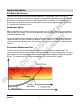
Product Information SE C OU he T ck / D A IS va C ila ON bi T lit IN y U ED EVS Model EX Overview The EVS EX is used for high end vibration protection in a low profile, Class 1 Division 1 package. It can be mounted directly to rotating or reciprocating equipment to monitor vibration and activate an on-board relay when a high vibration level is reached. The EX Model uses a piezoelectric crystal and state-of-the-art electronics to provide the highest degree of precision in a stand-alone monitoring system.
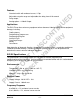
Features Standard switch with on-board sensor, 1.
4-20mA Output (Analog Option) Accuracy ± 5% of full scale at 1.5 ips, 100Hz, 21° C (69.8°F) SE C OU he T ck / D A IS va C ila ON bi T lit IN y U ED 20 mA corresponds to 1.5 or 3.0 ips peak (factory set) Alarm Level Potentiometer for field adjustable alarm level Alarm level range of 0.1-1.
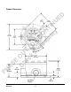
PH A SE C OU he T ck / D A IS va C ila ON bi T lit IN y U ED Product Dimensions Section 20 06-21-10 00-02-2003 -4-
Installation SE C OU he T ck / D A IS va C ila ON bi T lit IN y U ED Disassembly and Reassembly Always disconnect the power cord before disassembling. WARNING! Failure to disconnect the power before disassembling may cause personal injury and/or property damage. •Make sure that any disassembly is done in a clean, well ventilated, properly controlled static environment. •Always make sure that the assemblies and sub-assemblies are well supported and insulated when doing any repairs on the instrument.
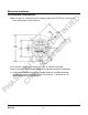
Mechanical Installation SE C OU he T ck / D A IS va C ila ON bi T lit IN y U ED Pre-Installation Requirements Make sure that the surface that you are going to mount the EVS EX to is flat and will fit the hole pattern for the enclosure. If the surface is rough, try to make the surface as smooth as possible. Always install the EVS EX perpendicular to the vibration force being monitored.
Vertical and Horizontal Installation SE C OU he T ck / D A IS va C ila ON bi T lit IN y U ED 1. Make sure you read the bearing or equipment manufacturers instruction for drilling and tapping equipment casing or housing before installing the EVS EX. 2. Drill and tap four holes for the four (1/4” x 20) bolts that fasten the EVS EX to the equipment casing, bearing housing or mounting plate. 3. Clean the mounting surface making sure there is no debris on the surface. 4. Align the EVS EX over the tapped holes.
Cabling and Wiring Installation SE C OU he T ck / D A IS va C ila ON bi T lit IN y U ED Standard EVS S-EX and Analog EVS-A-EX 1. Remove the top cover from the EVS-EX. 2. Place a slotted screw driver in the slot of the 8 pin connector. Pry the screw driver away from the back of the connector until the connector comes loose from the header. PH A 3.
SE C OU he T ck / D A IS va C ila ON bi T lit IN y U ED 4. Put the power cable through the bottom 3/4” NPT opening. (See Teflon Wrapping Technique at the end of this document.) 5. Connect the power cable wires as indicated in the pin out diagrams shown below. Pin out for Standard Switch PH A Pin out for Analog Option 6. Put the relay wires through the side ¾” NPT opening.
7. Connect the relay wires according to the pin out diagrams above. 8. Reconnect the 8-pin connector by pushing it onto the header until it snaps into place. SE C OU he T ck / D A IS va C ila ON bi T lit IN y U ED 9. Thread the conduit connectors into the EVS EX housing until snug. PH A 10. Screw on the top cover until snug.
External Standard Accelerometer Wiring SE C OU he T ck / D A IS va C ila ON bi T lit IN y U ED 1. Remove the EVS EX top cover. 2. Connect the Power and Relay wires per instructions above. 3. Place a slotted screw driver in the slot of the 3-pin connector. Pry the screw driver away from the back of the connector until the connector comes loose from the header. 4. Lift the connector off the header. 5. Connect the external accelerometer wires as indicated in the pin out diagram below.
6. Reconnect the 3-pin connector by pushing it onto the header until it snaps into place. 7. Thread the conduit connectors into the EVS EX housing until snug. SE C OU he T ck / D A IS va C ila ON bi T lit IN y U ED 8. Screw in the top cover until snug. External Charge Accelerometer Wiring 1. Remove the EVS EX top cover. 2. Connect the Power and Relay wires per instructions above. 3. Feed the Coaxial cable that leads from the Charge accelerometer through the bottom ¾” NPT opening. 4.
SE C OU he T ck / D A IS va C ila ON bi T lit IN y U ED Configuration Setting the Alarm Threshold WARNING! Always adjust the IPS alarm threshold to meet your specific alarm requirements in the environment the machinery is in. Setting the alarm threshold too high can result in property damage and/or personal injury. 1. Use a small Phillips or slotted head screw driver to adjust the Alarm Threshold IPS setting. 2.
3. If you are setting your vibration alarm as a function of the baseline (or a multiple of the baseline), first establish the baseline as follows: SE C OU he T ck / D A IS va C ila ON bi T lit IN y U ED Adjust the time delay to the maximum level of 10 seconds. Use a slotted narrow head screw driver and turn the pot clockwise until the indicator is pointing to 1.5 IPS. Starting with the Alarm Setting at the 1.
Setting the Delay Setpoint SE C OU he T ck / D A IS va C ila ON bi T lit IN y U ED WARNING! Always adjust the Delay to meet your specific requirements. Too long a delay can result in property damage and/or personal injury. 1. To adjust the Delay setpoint use a slotted narrow head screw driver. 2. Put the screw driver through the adjustment port and into the slot on the top of the delay potentiometer. 3.
Configuring Latching and Non-Latching/Fail-safe and Normal Modes SE C OU he T ck / D A IS va C ila ON bi T lit IN y U ED The alarm relays can be configured to operate in a latching or non-latching mode, Fail-safe or Normal mode. Latching Mode – When an alarm or shutdown condition is reached, the output remains in the alarm condition until it is reset. Non-Latching Mode – The output is automatically reset when the alarm condition no longer exists.
SE C OU he T ck / D A IS va C ila ON bi T lit IN y U ED The dip switch indicator allows you to select one of four modes by moving the black rectangles to indicate the state of the switch. These modes are illustrated in the following switch configuration examples.
Specifications SE C OU he T ck / D A IS va C ila ON bi T lit IN y U ED Environmental Temperature: -40° and +85°C (-40° and +185°F) Humidity: 0-95% non-condensing Vibration: 30 g’s max @ 500 Hz External Power Requirement Supply Voltage: 20 - 32 VDC ± 10% Supply Current: 100mA Max Frequency Response 6 to 500 Hz, ±5%, on-board sensor version 6 to 1,000 Hz, ±5%, external sensor version 4-20mA Output (Analog Option) Accuracy ±5% of full scale at 1.5 ips, 100Hz, 21° C (69.
Reset Input Activated by external N.O. relay or push button contact SE C OU he T ck / D A IS va C ila ON bi T lit IN y U ED Reset activation time: 0.5 seconds minimum Reset current < 10mA Approvals UL (Pending) CSA (Pending) Teflon Tape 1-2-3 Wrapping Technique The biggest reason for leaks via the conduit into electrical devices is often improper wrapping of the Teflon tape on the threads. Here’s a simple 1-2-3 technique that might help.
PH A SE C OU he T ck / D A IS va C ila ON bi T lit IN y U ED 3. Wrap the Teflon tape (3) times around the fitting, hold down on the threads with your thumb, and pull on the tape roll to 'cut' the tape. Don’t allow the tape to fray. You now have a properly wrapped fitting ready for use. Install the fitting hand tight, and then give it up to two turns with a wrench. If it wants to stop before two turns, DO NOT force the fitting. You can damage the threads or destroy the seal.