Model 405005x99B This Instruction Book contains information for several models. Read and keep this book for future reference. This book contains important information on SAFETY, ASSEMBLY, OPERATION, AND MAINTENANCE. PRODUCT INFORMATION The owner must be certain that all the product information is included with the unit. This information includes the INSTRUCTION BOOKS, the REPLACEMENT PARTS and the WARRANTIES. This information must be included to make sure state laws and other laws are followed.
TABLE OF CONTENTS WARRANTY . . . . . . . . . . . . . . . . . . . . . . . . . . . . . . . . . . . . . . RESPONSIBILITY OF THE OWNER . . . . . . . . . . . . . . . . . SAFETY RULES . . . . . . . . . . . . . . . . . . . . . . . . . . . . . . . . . . INTERNATIONAL PICTORIALS . . . . . . . . . . . . . . . . . . . . . ASSEMBLY . . . . . . . . . . . . . . . . . . . . . . . . . . . . . . . . . . . . . . . 2 3 3 9 10 PARTS BAG - CONTENTS . . . . . . . . . . . . . . . . . . . . . . . . . . . . . .
OWNER’S INFORMATION This instruction book is for several different models. The instructions are written for a person with some mechanical ability. Like most service books, not all the steps are described. Steps on how to loosen or tighten fasteners are steps anyone can follow with some mechanical ability. Read and follow these instructions before you use the unit. Know your product: If you understand the unit and how the unit operates, you will get the best performance.
OWNER’S INFORMATION c. Do not turn sharply. Use care when backing. d. Use counterweights or wheel weights when suggested in the Instruction Book. 18. Do not operate this machine if you are taking drugs or other medication which can cause drowsiness or affect your ability to operate this machine. 19. Do not use this machine if you are mentally or physically unable to operate this machine safely. 20.
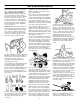
SAFE MOWING GUIDE Each person that operates power equipment must learn to use correct and safe mowing procedures. To help you learn, carefully read the following pages. Most of the time the operator was not correctly shown or did not read the instructions on the unit or in the Instruction Book before using the unit. Also, some operators do not have enough experience. The result is unsafe use, endangering the operator, bystanders and the equipment. Another result can be a poor appearance of the area mowed.
SAFE MOWING GUIDE mower was completely assembled at the store, you must still check the mower according to the assembly instructions. Make sure the mower is correctly assembled and that all fasteners are tight. Make sure the engine has the correct amount of oil. Check these items often during the life of the mower. Your mower has a gasoline engine. Gasoline is a dangerous fuel. Keep gasoline only in an approved safety gasoline container. Do not keep large amounts of gasoline.
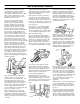
SAFE MOWING GUIDE Also, the grass bagger will function better when the engine is operating at maximum speed. On slopes, decrease the ground speed and use care making sure the mower feels safe to operate. feel new or excessive vibration, immediately stop the engine and check for the problem. Vibration can be a warning of a problem. Keep all nuts, bolts and screws tight. If the weather conditions are bad, do not mow. If weather conditions become bad, stop cutting and finish later.
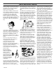
STEPS TO FOLLOW BEFORE MOWING F Be sure to dress correctly. Wear hard shoes, not sandals or tennis shoes. F Examine the blade. A blade that is bent, cracked, or damaged must be replaced with a factory replacement blade. F Fill the fuel tank outside. Clean off spilled fuel. F Read and follow the Owner’s Manual, the instructions with the engine, and the instructions with any attachments. Owner’s Manual instructions are for your safety and the safety of others. F Exhaust fumes are dangerous.
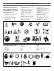
INTERNATIONAL PICTORIALS INTERNATIONAL PICTORIALS IMPORTANT: Some of the following pictorials are located on your unit or on literature supplied with the product. Before you operate the unit, learn and understand the purpose for each pictorial. Safety Warning Pictorials 1 2 3 4 Warning Shield Eyes. Explosive Gases Can Cause Blindness Or Injury. No Sparks, Flames or Smoking. Sulphuric Acid Can Cause Blindness Or Severe Burns 5 Flush Eyes Immediately With Water. Get Medical Help Fast.
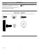
ASSEMBLY ASSEMBLY WARNING: Before doing any assembly or maintenance to the mower, remove the wire from the spark plug. Read and follow the assembly and adjustment instructions for your mower. All fasteners are in the parts bag. Do not discard any parts or material until the unit is assembled. NOTE: In this instruction book, left and right describe the location of a part with the operator on the seat. PARTS BAG - CONTENTS The fasteners and other loose parts are shown below.
ASSEMBLY 3. HOW TO INSTALL THE SEAT 1. Carefully remove the plastic bag from the seat. Use the fasteners shown below to install the seat. The fasteners are shown at full size. Check the operating position of the seat. If the seat needs to be adjusted, loosen the two wing bolts. Slide the seat forward or backward along the seat adjusting holes as shown. Tighten the wing bolts (A).
ASSEMBLY MAINTENANCE FREE BATTERY 3. IMPORTANT: Before you attach the battery cables to the battery, check the battery date. The battery date tells if the battery must be charged. Use a 12 volt battery charger to charge the battery. Charge at a rate of 6 amperes for one hour. If you do not have a battery charger, have an authorized service center charge the battery. 4. Install the battery and battery tray. Make sure the positive (+) terminal is on the left side. 1.
ASSEMBLY IMPORTANT! BEFORE YOU START MOWING - Check the engine oil. WARNING: Before doing any assembly or maintenance to the mower, remove the wire from the spark plug. - Fill the fuel tank with gasoline. - Check the level of the mower housing. - Check the air pressure of the tires. NOTE: In this instruction book, left and right describe the location of a part with the operator on the seat. - Make sure the battery cables are attached.
OPERATION Blade Rotation Control Throttle Control Lever Clutch / Brake Pedal Shift Lever Lift Lever Figure 4 LOCATION OF CONTROLS BLADE ROTATION CONTROL: Use the blade rotation control to start and stop the rotation of the blade. SHIFT LEVER: Use the shift lever to change the speed of the CLUTCH / BRAKE PEDAL: The pedal has two functions. The first function is a clutch. The second function is a brake. LIFT LEVER: Use the lift lever to change the height of cut.
OPERATION ATTACHMENTS Disengage Position This unit can use many different attachments. See the attachment page in this book. This unit can pull attachments like a lawn sweeper, a lawn aerator, a hopper spreader or a small trailer. This unit can not use attachments that engage the ground like a plow, a disk harrow, or a cultivator. For trailer and pull-behind attachments or trailers, the maximum gross weight is 250 pounds.
OPERATION HOW TO SET THE PARKING BRAKE 1. 2. 3. 4. Completely push the clutch/brake pedal forward. Lift the parking brake lever (Figure 6). Remove your foot from the clutch/brake pedal and then release the parking brake lever. Make sure the parking brake will hold the unit. To release the parking brake, completely push the clutch/brake pedal forward. The parking brake will automatically release. WARNING: Before you leave the operator’s position, move the shift lever to the neutral (N) position.
OPERATION HOW TO OPERATE WITH THE MOWER HOUSING WARNING: The deflector is a safety device. Do not remove the deflector. The deflector forces the discharged material toward the ground. Always keep the deflector in the down position. If the deflector is damaged, replace the deflector with an original equipment part from an authorized service center. 4. Slowly move the blade rotation control to the ENGAGE position. 5. Push the clutch/brake pedal completely forward. 6.
OPERATION CAUTION: A mixture of alcohol (ethanol or methanol) and gasoline (called gasohol), will attract moisture and cause acid deposits during storage. While the unit is in storage, the acids in the fuel can damage the fuel system. BEFORE STARTING THE ENGINE CHECK THE OIL NOTE: The engine was shipped from the factory filled with oil. Check the level of the oil. Add oil as needed. See the engine manufacturer’s instructions for the type of gasoline and oil to use.
OPERATION OPERATING TIPS 1. Check the blade rotation control for correct adjustment. For the blade(s) to disengage correctly, the adjustment must be correct. 5. Before you make an inspection, adjustment (except for the carburetor) or repair, make sure the wire from the spark plug is disconnected. 2. Before you use the unit, check the oil in the engine and add oil if necessary. 6. For longer life of the battery on electric start models, charge the battery every three months. 3.
MAINTENANCE MAINTENANCE CHART PROCEDURE M O W E R * EACH USE FIRST 2 HOURS EVERY 25 HOURS EVERY 50 HOURS EVERY 100 HOURS BEFORE STORAGE Blade, Inspect and Sharpen √ Blade Rotation Control, Check √ Brake, Check √ Clutch, Check √ Tires, Check √ √ Battery, Check and Charge √ √ Battery, Clean √ √ Lubrication * √ √ Dusty conditions every 25 hours. GENERAL RECOMMENDATIONS 1. 2. 3. 4. The owner’s responsibility is to maintain this product.
MAINTENANCE 9. Tighten the nut that holds the blade to a torque of 35 foot pounds (47,5 N-m). 10. Install the mower housing. See “How To Install The Mower Housing”. INSPECT BLADE WARNING: Before you inspect or remove the blade, disconnect the wire to the spark plug. If the blade hits an object, stop the engine. Check the unit for damage. The blade has sharp edges. When you hold the blade, use gloves or cloth material to protect your hands.
MAINTENANCE HOW TO ADJUST THE BLADE ROTATION CONTROL 6. Attach the wire to the spark plug. Mow for a short distance and again check the quality of cut. If necessary, move the blade drive spring to the bottom hole. 7. Again check the quality of cut. If the quality of cut has not improved, replace the mower drive belt. See “How To Replace The Mower Drive Belt”. If replacing the belt does not correct the problem, take the unit to an authorized service center. 8.
MAINTENANCE HOW TO CHECK AND ADJUST THE DRIVE BRAKE Completely push the clutch/brake pedal forward. Set the parking brake. Move the shift lever to the neutral (N) position. Push the unit. If the rear wheels rotate, adjust or replace the brake pads. Adjust the drive brake as follows. 1. The location of the drive brake is on the right side of the gearbox (Figure 15). 2. Make sure the parking brake is set and the shift lever is in neutral (N).
MAINTENANCE HOW TO ADJUST THE SHIFT LEVER Shift Lever If the NEUTRAL position on the shift lever does not match neutral on the gearbox, adjust the shift lever as follows. 1. Stop the engine. 2. Disconnect the adjuster nut from the shifter bracket (Figure 17). 3. Make sure the shift lever is in the NEUTRAL position. 4. Push the unit forward. Make sure the gearbox is in neutral. 5. To align the adjuster nut with the hole in the shifter bracket, turn the adjuster nut. 6.
MAINTENANCE WHERE TO LUBRICATE Apply grease with a brush to the areas shown. Lubricate the areas shown with engine oil. NOTE: Apply grease to the steering gear assembly. CAUTION: If the unit is operated in dry areas that have sand, use a dry graphite spray to lubricate the unit. Figure 19 HOW TO CHECK THE FUEL FILTER NOTE: Before you replace the fuel filter or the fuel line, the fuel tank must be empty. Clips If the fuel filter is dirty, the engine will run rough and have less performance.
MAINTENANCE HOW TO REMOVE THE MOWER HOUSING HOW TO INSTALL THE MOWER HOUSING 1. 2. 1. 2. Move the blade rotation control to the DISENGAGE position. Move the lift lever to the level adjustment position (Figure 21). Push the mower housing under the right side of the unit. Put the mower drive belt around the stack pulley. Make sure the “V” side of the mower drive belt is against the stack pulley. Also, make sure the mower drive belt is not twisted. 3.
MAINTENANCE HOW TO LEVEL THE MOWER HOUSING If the mower housing is level, the blade will cut easier and the lawn will look better. WARNING: Before you make an inspection, adjustment, or repair to the unit, disconnect the wire to the spark plug. Remove the spark plug wire to prevent the engine from starting by accident. Lift Lever 1. Make sure the unit is on a hard flat surface. 2. Check the air pressure in the tires. If the air pressure is incorrect, the mower housing will not cut level.
MAINTENANCE HOW TO REPLACE THE MOTION DRIVE BELT Shift Link REMOVAL 1. Remove the mower housing. See the instructions on “How To Remove The Mower Housing”. 2. Completely push the pedal forward and engage the parking brake. 3. Remove the idler pulley (Figure 26). Adjuster Nut Shifter Bracket Hair Pin Motion Drive Belt Figure 28 Drive Pulley 8.
MAINTENANCE INSTALLATION 1. Slide the motion drive belt between the stack pulley and the belt guides (Figure 29). Install the motion drive belt on the top pulley of the stack pulley. Make sure the “V” side of the belt is against the pulley. 2. Push the motion drive belt through the opening between the steering plate and the engine plate. 3. Install the end of the motion drive belt around the drive pulley (Figure 26). 4. Tighten the belt guides at the drive pulley (Figure 27). 5.
MAINTENANCE HOW TO REPLACE THE MOWER DRIVE BELT 1. Remove the mower housing. See the instructions on “How To Remove The Mower Housing”. 2. Pull the belt retainer away from the idler pulley and remove the mower drive belt (Figure 32). 3. Pull the belt retainer away from the right mandrel pulley and remove the mower drive belt. 4. Pull the belt retainer away from the left mandrel pulley and remove the mower drive belt.
MAINTENANCE HOW TO INSTALL THE WHEELS Cotter Pin If the wheels must be removed for service, make sure they are installed as follows. Hub Cap Washer Washer Front Wheel 1. Make sure the valve stem is to the outside of the tractor. Slide the front wheel on the spindle (See Figure 33). Spindle 2. Fasten the front wheel with washer and cotter pin. Bend the ends of the cotter pin apart to keep the front wheel on the spindle. Valve Stem 3. If your model has hub caps, install the hub caps.
MAINTENANCE 3. HOW TO REPLACE THE FUSE Install a new light bulb. Align the light socket with the notches in the bezel and turn the light socket to lock in position. If the fuse is blown, the engine will not start. The location of the fuse is next to the battery. Remove the fuse and replace with a automotive fuse (Figure 35). Automotive Fuse Bezel Figure 35 Light Bulb HOW TO REPLACE THE LIGHT BULB 1. 2. Raise the tractor hood.
TROUBLE SHOOTING CHART PROBLEM: The engine will not start. PROBLEM: A hot engine causes a decrease in power. 1. 2. 1. 2. 3. 4. 3. 4. 5. 6. Follow the steps, “How To Start The Engine” in this book. Electric-Start Models: Clean the battery terminals. Tighten the cables. Drain the fuel tank. Clean the fuel line. Replace the fuel filter. Remove the spark plug(s). Move the throttle to the SLOW position. Turn the ignition key to the ON position. Try to start the engine several times. Install the spark plug.
Only use a factory repair part. Repair parts, except for the engine or the transmission, are available from the store where the unit was purchased, a service shop recommended by the store, or an authorized service shop found in the yellow pages of the telephone directory. If you cannot get a repair part or service as described above, call or write to the Central Parts Distributor shown below.
NOTES F-040707L 35
MODEL 405005x99B 13 11 14 REPAIR PARTS CHASSIS & HOOD 2 8 10 1 15 7 16 12 2 70 9 3 4 6 17 5 52 57 58 25 54 27 18 28 22 21 50 20 29 23 30 58 19 24 32 16 59 33 16 31 34 47 35 53 16 26 51 46 37 31 16 48 45 36 44 38 16 43 16 16 49 40 41 42 F-040707L 36 39
MODEL 405005x99B REPAIR PARTS CHASSIS & HOOD Key No. Part No. Description Key No. Part No.
MODEL 405005x99B REPAIR PARTS MOTION DRIVE 1 2 3 7 4 8 9 19 20 5 17 54 15 34 21 60 11 13 12 16 6 55 54 10 6 14 22 5 5 18 23 25 24 27 26 56 43 57 44 61 8 40 28 40 17 39 41 29 38 30 37 45 50 17 35 33 58 42 46 31 36 59 37 47 53 49 48 52 F-040707L 51 38 32
MODEL 405005x99B REPAIR PARTS MOTION DRIVE Key No. Part No. Description Key No. Part No.
MODEL 405005x99B REPAIR PARTS STEERING 3 40 2 41 1 30 13 43 6 39 30 17 30 4 5 18 6 14 30 37 20 12 7 15 30 8 19 9 30 16 10 20 11 26 21 22 25 27 33 34 23 25 31 28 24 25 29 31 22 24 19 23 32 38 36 F-040707L 25 35 40
MODEL 405005x99B REPAIR PARTS STEERING Key No. Part No. Description Key No. Part No.
MODEL 405005x99B REPAIR PARTS MOWER HOUSING SUSPENSION 9 1 2 10 13 15 14 16 17 4 3 21 12 12 14 22 11 11 15 24 18 24 5 25 19 27 23 8 6 22 14 7 20 24 33 11 34 36 20 38 25 31 37 24 43 32 26 30 45 32 40 26 25 39 41 30 31 39 24 25 15 44 15 42 7 24 F-040707L 42
MODEL 405005x99B REPAIR PARTS MOWER HOUSING SUSPENSION Key No. Part No. Description Key No. Part No.
MODEL 405005x99B REPAIR PARTS MOWER HOUSING 2 55 2 1 1 3 52 4 53 24 6 25 10 24 8 20 5 15 47 13 5 47 26 11 9 10 6 12 24 27 21 8 9 19 22 20 19 7 15 16 11 22 22 17 17 5 22 5 21 22 23 13 28 23 22 7 29 17 5 30 23 22 5 26 22 18 22 23 48 17 50 31 17 46 32 33 32 53 17 14 33 33 45 33 5 33 42 33 34 33 36 44 43 34 41 36 37 35 42 38 38 37 39 40 39 40 F-040707L 51 44
MODEL 405005x99B * REPAIR PARTS MOWER HOUSING Key No. Part No. Description Key No. Part No. Description 1 092851 Pulley, Jackshaft 29 166x42 Spring 2 15x140 Nut, Hex 30 094142E700 Bracket, Suspension 3 037x62 Belt, Mower Drive 31 091770E700 Plate 4 690387 Pulley, Idler 32 015x88 Nut, Flange 5 015x84 Nut, Flange 33 002x53 Bolt, Carriage 6 1001197 Spacer, Pulley 34 1001200 Mandrell (Includes Key No.
MODEL 405005x99B REPAIR PARTS ENGINE MOUNT 1 2 9 3 4 26 5 6 15 16 8 15 17 18 10 19 7 22 22 21 23 21 23 11 14 13 F-040707L 46 12
MODEL 405005x99B REPAIR PARTS ENGINE MOUNT Key No. Part No.
MODEL 405005x99B REPAIR PARTS ELECTRICAL SYSTEM 1 ARMATURE SPARK PLUG VILOT VILOT VILOT 2 YELLOW BLACK STATOR BLACK HEADLIGHT HARNESS BLACK YELLOW START SWITCH 3 BLACK AC OUTPUT 4 ORANGE NO DIODE NC YELLOW RED WHITE AC RED DC BLACK RED DC OUTPUT YELLOW YELLOW ORANGE ORANGE SOLENOID PTO SWITCH DISENGAGED NO 15 AMP FUSE 4 STARTER 5 RED 6 RED 9 NC SEAT SWITCH HARNESS 7 11 RED BLACK YELLOW 8 NC YELLOW SEAT SWITCH UNOCCUPIED ORANGE YELLOW YELLOW YELLOW F-040707L 48
MODEL 405005x99B Key No. F-040707L REPAIR PARTS ELECTRICAL SYSTEM Part No.
F-040707L 50
A Adjustments Blade Rotation Control, 22 Clutch, 23 Drive Brake, 23 Mower Housing, Level, 27 Shift Lever, 24 Attachments, 15, 52 B Battery Charge, 24 Check, 12 Clean, 24 Install, 12 Removal, 24 Storage, 32 Belt Motion Drive Adjust, 23 Replace, 28 Mower Drive Adjust, 22 Replace, 30 Blade Inspect, 21 Remove And Install, 21 Sharpen, 21 Blade Control Lever, Operation, 15 Blade Rotation Control Adjust, 22 Location, 14 C Clutch Adjust, 23 Check, 23 Clutch / Brake Pedal, Location, 14 Controls, Location, 14 Cutti
LAWN TRACTOR ACCESSORIES Make your Lawn Tractor do more than you ever imagined. The accessories shown on this page can be used on your Lawn Tractor. See the Store or Dealer where you purchased your Lawn Tractor. If you are unable to obtain the necessary information, contact the Central Parts Distribution Center for your area as listed in your Repair Parts Book. Î Î LAWN SWEEPER Model No. 24720 SNOW BLADE Model No. 24478 GRASS BAGGER Model No. 24767 9 Bushel Capacity SNOW THROWER Model No.