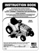
This Instruction Book Contains Information For Several Models. Read And Keep This Book For Future Reference. This Book Contains Important SAFETY, ASSEMBLy Information On: OPERATION AND MAINTENANCE. PRODUCT INFORMATION The owner must be certain that all the product Information Is Included with this unit. This Information Includes the INSTRUCTION BOOKS, the REPLACEMENT PARTS and the WARRANTIES. This Information must be Included to make sure state laws and other laws are followed.
TABLE OF CONTENTS WARRANTY ...................................... RESPONSIBILITY OF THE RULES SAFETY OWNER ................. 2 MOWING AND BAGGING TIPS 3 HOW TO CHANGE THE MULCHER 3 .................................. MAINTENANCE .......................... 19 2O PLATE ................ 21 ................................... MAINTENANCE 9 HOW TO CHECK THE MUFFLER 9 HOW TO REMOVE AND INSTALL THE BLADE ............
OWNER'S INFORMATION This instructionbook is forseveral different models. The instructions are written for a person with some mechanical ability.Like most service books, not all the steps are described. Steps on how to loosen or tighten fasteners are steps anyone can followwith some mechanical ability.Read and followthese instructions before you use the unit. chased in an assembled condition. On assembled units, it is the responsibility of the owner to make sure the unit is correctly assembled.
OWNER'S INFORMATION 20. Do not use this machine if you are mentally or physically unable to operate this machine safely. II. Slope operation Slopes and rough terrain ere major factors related to loss- of- control and tip- over accidents, which can result in severe injury or death. ALL slopes require extra caution. If you cannot back up the slope or if you feel uneasy on the slope, do not mow it. See the =Slope Guide" in the back of this book to check for safe operation. DO 1, 2. 3. 4. 5. 6. 7, 8.
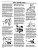
SAFE MOWING GUIDE Eachperson thatoperates power controls and how they work. In an equipment mustlearntousecorrect and emergency, how fast you can stop the safemowing procedures. Tohelpyou blade is important. Learn how to control learn,carefullyreadthefollowing the mower at all times. pages,Mostofthetimetheoperator was Many engines are started by hand.
SAFE MOWING GUIDE store,youmuststillcheck the mower according to the assembly instructions. Make sure the mower is correctly assembled and that all fasteners are tight. Make sure the engine has the correct amount of oil. Check these items often during the life of the mower. Your mower has a gasoline engine. Gasoline is a dangerous fuel. Keep gasoline only in an approved safety gasoline container. Do not keep large amounts of gasoline, When you add gasoline to the fuel tank, do not smoke.
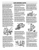
SAFE MOWING GUIDE Also, the grass bagger will function better when the engine is operating at maximum speed. On slopes, decrease the ground speed and use care making sure the mower feels safe to operate. feel new or excessive vibration, immediately stop the engine and check for the problem. Vibration can be a warning of a problem. Keep all nuts, bolts and screws tight. If the weather conditions are bad, do not mow. If weather conditions become bad, stop cutting and finish later.
STEPS TO FOLLOW BEFORE MOWING • Be sure to dress correctly. Wear hard shoes, not sandals or tennis shoes. • Examine the blade. A blade that is bent, cracked, or damaged must be replaced with a factory replacement blade. • Fill the fuel tank outside. Clean off spilled fuel. • Read and follow the Owner's Manual, the instructions with the engine, and the instructions with any attachments. Owner's Manual instructions are for your safety and the safety of others. • Exhaust fumes are dangerous.
ASSEMBLY ASSEMBLY This instructionbook is for several models. Some parts or accessories are not included on all models. Read and follow the assembly and adjustment instructions for your mower. All fasteners are in the parts bag. Do not discard any parts or material until the unit is assembled. A nance to theBefore mower,doing remove wire fromorthemaintespark WARNING: anytheassembly plug, NOTE: In this instruction book, left and right describe the location of a part with the operator on the seat.
ASSEMBLY HOW TO INSTALL THE SEAT 3. Use the fasteners shown below to install the seat. The fasteners are shown at full size. Check the operating position of the seat. If the seat needs to be adjusted, loosen the two wing bolts. Slide the seat forward or backward along the seat adjusting holes as shown. Tighten the wing bolts (A). Seat Hinge © (A) Seat AdjusSngHole (a) 94160 ,A 17x47Z 1. Carefully remove the plastic bag from the seat. 2.
ASSEMBLY HOW TO INSTALL THE MOWER HOUSING 4. Put the mower drive belt around the stack pulley. See Illustration "G" Figure 5. Make sure the _ side of the mower drive belt is against the stack pulley. Also, make sure the mower drive belt is not twisted. 5. Attach the front hanger to the axle support with the hanger rod. Fasten with the fasteners as shown. See illustration =F". 6. Make sure the mower drive belt is between the stack pulley and the two belt guides. See illustration "G".
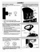
ASSEMBLY MAINTENANCE FREE BATTERY HOW TO CHARGE THE MAINTENANCE FREE BATFERY IMPORTANT: Before you attach the battery cables to the battery, check the battery date. The battery date tells if the battery must be charged. 1. Check the top of the battery for the location of the battery date (Figure 6). 2. If the battery is put into service before the battery date. the battery cables can be attached without charging the battery. See =How To Install The Battery Cables'. 3. A dJL 1.
OPERATION ThrottleConlrol Lever BladeRotation Control Brake Pedal Speed Con_'ol Pedal Lift Lever Figure 7 LOCATION OF CONTROLS BLADE ROTATION CONTROL: usethebladerotation AUTOMATIC DRIVE DISCONNECT: use theauto- maticdrive control to start and stop the rotation of the blades. disconnect, located under the seat, to disengage the transmission. BRAKE PEDAL: LIFT LEVER: use the liftleverto changethe heightof cut. Use the brake pedal to quickly stop.
OPERATION ATTACHMENTS HOW TO USE THE BLADE ROTATIONCONTROL This unit can use many different attachments. See the attachment page in this book. This unit can pull attachments like a lawn sweeper, a lawn aerator, or a hopper spreader. This unitcan not use attachments that engage the ground like a plow, a disk harrow, or a cultivator. HOW TO USE THE THROTTLE The blade rotation control is next to the steering wheel (Figure 8).
OPERATION HOW TO USE THE SPEED CONTROL PEDAL The drive system uses a Hydrostatic Automatic Drive transmission. The Hydrostatic transmission is very easy to operate. This type of drive system does not require a shift lever or a clutch pedal. The speed and direction of travel is controlled by a single speed control pedal operated with your right foot. Do not use the left brake pedal in normal operation. Only use the left brake pedal to quickly stop in an emergency. HOW TO DRIVE FORWARD 1.
OPERATION HOW TO SET THE PARKING BRAKE 1. Completely push the brake pedal forward, 2. Liftthe parking brake lever (Figure tt), 3. Remove your foot/TOm the brake pedal and then release the parking brake lever. Make sure the parking brake will hold the unit. 4. To release the parking brake, completely push the brake pedal forward. The parking brake will automatically release. WARNING: Before you leave the operator's position, parking Move tothe rotation control Set to the move thebrake.
OPERATION HOW TO OPERATE WITH THE MOWER HOUSING ,& WARNING: The deflector is • safety device, Do not remove the deflector, The deflector forces the discharged material toward the ground. Always keep the deflector in the down position. If the deflector is damaged, replace the deflector with an original equipment part from an authorized service center. 1, Start the engine. 2. Release the parking brake. 3. Move the lift lever to a height of cut position.
OPERATION BEFORE CHECK STARTING CAUTION: A mixture of alcohol (ethanol or methanol) and gasoline (called gasohol), will attract moisture and cause acid deposits during storage. While the unit is in storage, the acids in the fuel can damage the fuel system. THE ENGINE THE OIL NOTE: The engine was shipped from the factory filled with oil. Check the level of the oil. Add oil as needed.
OPERATION OPERATING TIPS 1, Check the blade rotation control for correct adjustment. For the blade(s) to disengage correctly, the adjustment must be correct. 5. 2. Before you use the unit, check the oil in the engine and add oil if necessary. 6. For _onger life ofthe battery on electric start models, charge the battery every three months. 3. If the engine will not start, first make sure the wire is attached to the spark plug. 7.
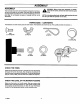
OPERATION HOW TO CHANGE THE MULCHER PLATE Deflector I DeflectorBracket connect the To wire from the sure disthe WARNING: prevent the spark engineplug. fromMake starting, blade rotation control is in the DISENGAGE position. A The mulcher plate lets you mulch the grass for a clean, fine cut. To discharge the grass out the side or into a grass bagger, remove the mulcher plate as follows. How To Remove The Mulcher Plate 1. Raise the deflector.
MAINTENANCE MAINTENANCECHART PROCEDURE EACH USE RRST 2 HOURS EVERY 25 HOURS EVERY 50 HOURS EVERY 100 HOURS BEFORE STORAGE iiiiiiiiiiiiiiiiiiiiiiiiiiiiiiiiiiiiiiiiiiiiiiiiiiiiiiiiiiiiiiiiiiiiiiii M O W E R Blade Rotation Control, Check ¢ Motion Drive Belt, Check ¢ Battery, Check and Charge ¢ ¢ GENERAL RECOMMENDATIONS 1. 2. WARNING: The owner's responsibility is to maintain this product. This will extend the life ofthe product end is also necessary to maintain warranty coverage.
MAINTENANCE INSPECT BLADE 9. WARNING: Before you inspect or remove the blade, disconnect the wire to the spark plug. If the blade hits A Tighten the nut that holds the blade to a torque of 35 foot pounds (47,5 N- m). 10. Install the mower housing. See "How To Install The Mower Housing". n object, stop has the sharp engine.edges. CheckWhen the unit age. The blade you for holddamthe blade, use gloves or cloth material to protect your hands.
MAINTENANCE HOW TO ADJUST THE BLADE ROTATION CONTROL A 6. Attach the wire to the spark plug. Mow for a short distance and again check the quality of cut. If necessary, move the blade drive spring to the bottom hole. 7. Again check the quality of cut. If the quality of cut has not improved, replace the mower drive belt. See =How To Replace The Mower Drive Belt'. If replacing the belt does not correct the problem, take the unit to an authodzed service center. ARNING: preventcorrectly.
MAINTENANCE HOW TO CHECK AND ADJUST THE DRIVE BRAKE Completely push the brake pedal forward. Set the parking brake. Move the automatic drive disconnect to the PUSH position. Push the unit. If the rear wheels rotate, adjust or replace the brake pads. Adjust the drive brake as follows. 1. The location of the drive brake is on the right side of the gearbox (Figure 22). 2, Make sure the parking brake is set and the automatic drive disconnect is in the PUSH position.
MAINTENANCE HOW TO ADJUST THE SPEED CONTROL PEDAL If the unit will not go into REVERSE or ifthe unit moves very slowly in REVERSE, adjust the speed control pedal as follows. 1. Stop the engine. 2. Set the parking brake. 3. Remove the hair pin from the adjuster nut (Figure 24). Disconnect the adjuster nut from the yoke assembly. 4, Rotate the adjuster nut one rum in the direction shown in Figure 24.
MAINTENANCE WHERE TO LUBRICATE ,,_"p Models with grease fittings: Lubricate with grease gun. _F_%,_f p Apply grease with a brush to the areas shown. Lubricate the areas shown with engine oil. NOTE: Apply grease to the steering gear assembly. CAUTION: ff the unit is operated in dry areas that have sand, use a dry graphite spray to lubricate the unit. Figure 26 HOW TO CHECK THE FUEL FILTER NOTE: Before you replace the fuel filter orthe fuel line, the fuel tank must be empty.
MAINTENANCE HOW TO REMOVE 1. 2. THE MOWER HOUSING HOW TO INSTALL Move the blade rotation control to the DISENGAGE position. Move the lift lever to the level adjustment position (Figure 28). WARNING: _lb 3. 4. 5. 6. 7. 8. 9. Remove the hair pins and the washers from the adjuster arms (Figure 29). See illustrations "C" and "D". Remove the hair pins and washers from the suspension links. Figure28 See illustrations =A"and "B". Disconnect the extension spring from the blade control rod.
MAINTENANCE HOW TO ADJUST THE GAUGE WHEELS The axle bolts for the gauge wheels were mounted in the LOW cut position. To change the position of the gauge wheels, move the axle bolts as follows. IMPORTANT: Before you adjust the gauge wheels, you must do the following. Make sure the mower housing is level. Make sure the height of cut Is set at the height you want for your lawn. Mow a short distance on a flat level area and look at the area that was cut.
MAINTENANCE HOW TO LEVEL THE MOWER HOUSING Ifthe mower housing is level, the blade will cut easier and the lawn will look better. A WARNING: Before you make an inspection, adjustment, or repair to the unit, disconnect the wire to the spark plug. Remove the spark plug wire to prevent the engine from starting by accident. 1. Make sure the unit is on a hard fiat surface. 2, Check the air pressure in the tires. If the air pressure is incorrect, the mower housing will not cut level.
MAINTENANCE HOW TO REPLACE THE MOTION DRIVE BELT REMOVAL 1. Remove the mower housing. See the instructions on =How To Remove The Mower Housing". 2. Completely push the pedal forward and engage the parking brake. 3. Loosen the belt guide at the idler pulley. Move the belt guide away from the idler pulley (Figure 36). 4. Remove the idler pulley (Figure 36). 5. Disengage the parking brake. 6. Remove the V- idler pulley. 7. Remove the belt guide at the middle idler pulley. 8.
MAINTENANCE HOW TO REPLACE THE PRIMARY MOWER DRIVE BELT HOW TO REPLACE THE SECONDARY MOWER DRIVE BELT 1. Remove the mower housing. See the instructions on "How To Remove The Mower HousingW. 1. 2. Remove the three screws from the left pulley cover. Remove the pulley cover. 3, Pull the belt retainer away from the idler pulley. Remove the primary mower drive belt from the idler pulley. 4. 4. Move the brake pad assembly away from the stack pulley.
MAINTENANCE HOW TO REPLACE THE FUSE 3, Install a new light bulb.Align the light socket with the notches in the bezel and turn the light socket to lock in position. If the fuse is blown, the engine will not start. The location ofthe fuse is next to the battery. Remove the fuse and replace with a automotive fuse (Figure 40). A_omo_veF_e Figure 40 HOW TO REPLACE THE LIGHT BULB Raise the tractor hood. 1, 2.
TROUBLE SHOOTING CHART 4. 5. PROBLEM: The engine will not start. 1. Follow the steps, =How To Start The Engine" in this book. 2. Electric- Start Models: Clean the battery terminals. Tighten the cables. 3. Drain the fuel tank. Clean the fuel line. Replace the fuel filter. 4. Remove the spark plug (s). Move the throttle to the SLOW position. Turn the ignition key to the ON position. Try to start the engine several times. Install the spark plug. Replace the spark plug. Adjust the carburetor. 5. 6.
SLOPE GUIDE 1o t*) I I I JOperate e walk-behind mower across the face of slopes, never up or down slopes. mower up or down slopes, never across the face of slopes. 4_ On a riding mower to determine if e slope is safe to mow: (1) disengage the blade(e), (2) put the unit In reverse, and (3) try to back straight up the slope, if you can back up the slope, it Is generally safe to mow.
INDEX F A Adjustments Blade Rotation Control, 23 Clutch, 24 Drive Brake, 24 Mower Housing, Level, 29 Speed Control Pedal, 25 Attachments, 14, 36 Filter, Fuel, 26 AutomaticDriveDisconnect, Operation,15 Headlight Switch, Location, 13 B Battery Charge, 25 Check, 12 Clean, 25 Install, 12 Removal, 25 Storage, 32 Belt Motion Drive Adjust, 24 Replace, 30 Mower Drive, Adjust, 23 Mower Drive Belts, Replace, 31 Blade Inspect, 22 Remove And Install, 22 Sharpen, 22 Blade Rotation Control Adjust, 23 Location, 13 O
LAWN TRACTOR ACCESSORIES Make your Lawn Tractor do more than you ever imagined. The accessories shown on this page can be used on your Lawn Tractor. See the Store or Dealer where you purchased your Lawn Tractor. If you are unable to obtain the necessary information, contact the Central Parts Distribution Center for your area as listed in your Repair Parts Book. LAWN SWEEPER Model No. 24720 SNOW BLADE Model No. 24476 GRASS BAGGER Model No. 24762 9 Bushel Capacity (For42" and 46") SNOW THROWER Model No.