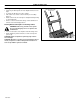
OWNER’S MANUAL SNOW THROWER 120 V.A.C. 6.5 AMP. 60 Hz. Double insulated 15” clearing width Model No. 615000x30NA Caution: Read and Follow all Safety Rules and Instructions Before Operating This Equipment MANUEL D’UTILISATION CHASSE–NEIGE De 15 po Double Isolation 12 V.C.A., 6.
TABLE OF CONTENTS WARRANTY 2 OPERATING INSTRUCTIONS 6 SAFE OPERATING PRACTICES 3 MAINTENANCE AND STORAGE 9 ASSEMBLY 5 REPAIR PARTS 12 ONE YEAR LIMITED WARRANTY Murray, Inc.
IMPORTANT SAFE OPERATION PRACTICES FOR WALK–BEHIND SNOW BLOWER DO NOT OPERATE THIS EQUIPMENT BEFORE READING THIS MANUAL Read entire owner’s manual before attempting to assemble or operate this Snowthrower. S If Snowthrower is to be left unattended, remove key and disconnect from power source. Before Operation S If extension cord is damaged in any way while plugged in – pull extension cord from wall receptacle. Replace damaged cord immediately S Read and understand this manual.
ASSEMBLY Your Snowthrower was completely assembled at the factory, except for the upper handle assembly. Plastic Strain Relief Spare Key Shipping Carton Carefully remove complete unit from carton. Make sure parts bag and all components have been removed before discarding carton. Plastic Probe The shipping carton contains the following items: S Snowthrower housing, with lower handles attached. S Upper handle loosely attached to lower handle by the wire harness.
ASSEMBLY S Insert plastic probe supplied into right handle hole, from the inside of the handle. This will ensure wire harness will not be pinched or damaged while inserting carriage bolt. Figure 4. Plastic Probe S Insert carriage bolt from outside of right handle while removing plastic probe. Figure 5. Inside Right Handle S Insert carriage bolt into left handle assembly. Figure 4 S Assemble locknuts to carriage bolts and fasten securely with mini wrench supplied.
OPERATION Know your snow blower and its controls. Be sure you (or any other operator) have read and understood the Operation Precautions listed on page 3 of this manual. This Snowthrower conforms to applicable North American safety standards.
OPERATION In deep snow it may be necessary to make two or three passes over an area in order to clear it acceptably. Operating Instructions WARNING: The Snowthrower is designed to clear snow from level surfaces, such as driveways and sidewalks. Caution should be exercised while operating Snowthrower on steep sloping areas. WARNING: Never direct snow discharge towards bystanders, glass enclosures or automobiles.
OPERATION Discharge Direction Adjustment Directional Discharge Control Rod S Snow may be discharged to the left, straight forward, or to the right. S To change the direction proceed as follows: S Pull control rod, to unlock control rod from present setting. Figure 9. S Rotate control rod to the left, right or straight ahead depending on desired direction. S Release control rod at desired setting, control rod will lock in full left, center and full right positions.
MAINTENANCE Lubrication Your Snowthrower does not require any lubrication for the life of the Snowthrower. Replacing Impeller Blades S Remove all 4 securing screws for each of the 2 impeller blades, and place aside. Figure 10. S Remove worn or damaged impeller blades. Figure 10. S Insert new impeller blades into slots in impeller and align holes. Figure 10. S Replace the 8 screws removed and fasten securely. S Discard old impeller blades.
F-031061C 10
Parts List - Model 615000x30NA Liste de pièces - Modèle 615000x30NA F-031061C 11
MODEL 615000x30NA REPAIR PARTS 342966 F-031061C 12
MODEL 615000x30NA Key No. Part No. REPAIR PARTS Description Key No. Part No.
MODEL 615000x30NA REPAIR PARTS DECALS 71 85 76 79 64 84 60 70 78 86 342436 Key No. Part No.
TABLE DES MATIÈRES PIÈCES DE RECHANGE GARANTIE MESURES DE SÉCURITÉ MONTAGE FONCTIONNEMENT ENTRETIEN ET REMISAGE 12 15 16 17 19 22 GARANTIE LIMITEE DE UN ANO Murray, Inc.
ATTENTION CONSEILS DE SÉCURITÉ POUR CHASSE–NEIGE À MAIN LIRE CE MANUEL AVANT D’UTILISER CET ÉQUIPEMENT S AVERTISSEMENT : MANIPULER LE CORDON ÉLECTRIQUE AVEC PRÉCAUTION – Ne pas déplacer le chasse–neige par le cordon ni le débrancher en tirant brusquement dessus. Tenir le cordon à l’écart de chaleur, d’huile et d’objets coupants. S Tenir les mains et les pieds à l’écart des pièces mobiles. Se tenir à l’écart de la goulotte d’éjection. S Ne pas forcer le chasse–neige.
ASSEMBLAGE Votre chasse–neige a été entièrement monté en usine, à l’exception du manche. Petite clé/Poulie motrice Clé de rechange Carton d’expédition Sortir soigneusement la machine du carton. S’assurer que le sac de pièces et tous les éléments on été retirés du carton avant de jeter celui–ci.
ASSEMBLAGE S Insérer la cheville de plastique fournie dans le trou de la poignée de droite, de l’intérieur. Ceci évitera que le faisceau de câbles soit pincé ou endommagé lors de l’insertion du boulon à tête ronde. Figure 4. Sonde de plastique S Insérer le boulon à tête ronde de l’extérieur de la poignée de droite tout en enlevant la cheville en plastique. Figure 5. Intérieur du manche droit S Insérer le boulon à tête ronde dans le tube du manche gauche.
FONCTIONNEMENT Apprendre à connaître le chasse–neige et ses commandes. Lire et bien comprendre les conseils de sécurité donnés en page 3. Ne pas avancer le chasse–neige trop loin de l’appui des pieds. Garder constamment un bon appui sur le sol.
FONCTIONNEMENT S’il est nécessaire de déneiger des surfaces irrégulières ou revêtues de gravier, appuyer sur le guidon pour relever les lames de l’impulseur et éviter qu’elles ne heurtent des surfaces irrégulières ou du gravier. En neige profonde, il peut être nécessaire de passer deux ou trois fous sur le même endroit pour le dégager entièrement. Fonctionnement AVERTISSEMENT: Le chasse–neige doit être utilisé sur des surfaces nivelées telles que trottoirs et allées.
FONCTIONNEMENT Réglage de l’orientation de la goulotte d’éjection Goulotte d’éjection directionnelle S La neige peut être éjectée vers la gauche, en avant ou vers la droite. S Pour changer la direction d’éjection, procéder comme suit : S Tirer sur la tige de commande pour la dégager de la position présente. Figure 9. S Tourner la tige de commande vers la droite, vers la gauche ou au centre, selon la position voulue.
FONCTIONNEMENT Lubrification Votre chasse–neige ne nécessite aucune lubrification durant toute sa durée de vie. Remplacement des lames de l’impulseur S Déposer les 4 vis de chacune des 2 lames de l’impulseur et les mettre de côté Figure 10. S Déposer les lames usées ou endommagées. Figure 10. S Insérer les nouvelles lames de l’impulseur dans les fentes de l’impulseur et aligner les trous. Figure 10. S Replacer les 8 vis déposées et les serrer fermement. S Jeter les lames d’impulseur usagées.
F-031061C 23
MURRAY, INC. CENTRAL PARTS DISTRIBUTORS DISTRIBUTEURS RÉGIONAUX DE PIÈCES MURRAY, INC. BILLIOU'S, INC. 1343 South Main St. Porterville, CA. 93257 (559) 784-4102 1-877-245-5468 FAX 1-800-226-7337 Arizona, California, Hawaii, Nevada BROWN & WISER, INC. 9991 S.W. Avery Street P.O. Box 1109 Tualatin, OR.