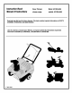
InstructionBook Manueld'instructions Snow Thrower Model 621301x89A chasse-neige mod61e 621301x89A Read and keep this book for future reference. This book contains important information on SAFETY, ASSEMBLY,OPERATION,AND MAINTENANCE. Lisez et conservez ce manuel pour r_f_rence. Ce manuel contient des informations importantes concernant la SECURITE, LE MONTAGE, L'UTILISATIONET L'ENTRETIEN.
NOTE: This unit is equipped with an internal combustion engine and must not be used on or near any unimproved forest-covered, brush-covered or grass-covered land unless the engine's exhaust system is equipped with a spark arrester meeting applicable local or state laws (if any).
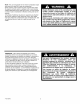
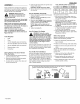
1 2 8 2 REAR 1 14 11 2 3 4 2 2 t 6 _6 16 17 2 \ 15 Fq)O1167M 3
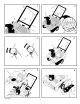
Z _8 9 4 2 5 4 4 6 4 12 2 5 5 F--OOl167M
1.
ENGLISH CONTENTS PRODUCT INFORMATION OWNER'S INFORMATION INTERNATIONAL PICTORIALS ASSEMBLY OPERATION MAINTENANCE MAINTENANCE CHART TROUBLE SHOOTING CHART 6 6 7 9 10 12 12 14 TWO YEAR LIMITED WARRANTY Murray, Inc.
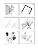
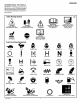
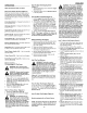
ENGLISH INTERNATIONAL PICTORIALS IMPORTANT: The following pictorials are located on your unit or on literature supplied with the product. Before you operate the unit, learn and understand the purpose for each pictorial. 15 Safety Warning Symbols DANGER Thrown Objects. Keep Bystanders Away, DANGER Thrown Objects. Keep Bystanders Away.
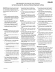
ENGLISH Safe Operation Practices for Snow Throwers As Recommended By: American National Standards Institute. IMPORTANT: Safety standards require operator presence controls to minimize the risk of injury. Your snow thrower is equipped with such controls. Do not attempt to defeat the function of the operator presence control under any circumstances. Training 1. 2. 7. Never attempt to make any adjustments while the engine (motor) is running (except when specifically recommended by manufacturer). 11.
ENGLISH ASSEMBLY Read and follow the assembly and adjustment instructions for your snow thrower. All fasteners are in the parts bag. Do not discard any parts or material until the unit is assembled. 4. Hold onto the lower handle and pull the snow thrower off the carton. CAUTION: DO NOT back over cables. 5. Remove the packing material from the handle assembly. How To Assemble assembly or maintenance to the _hk WARNING: Before doing any snow thrower, remove the wire from the spark plug.
ENGLISH OPERATION How To Stop (Figure NOTE: Illustrations begin on page 3. Know Thrower Your Snow (Figure Discharging 2) 2) Crank Assembly (2) - Changes the direction of the discharge chute. Discharge Chute (3) - Changes the distance the snow is thrown. Auger Drive Lever (5) - Starts and stops the auger which propels the snow thrower. snow, release the auger 2. To stop the engine, turn the ignition to the off position. How To Move Forward (Figure key (8) 4) 1.
ENGLISH NOTE: In temperatures below O°F, allow the engine to warm up for several minutes before blowing snow. indoors or in enclosed, poorly venARNING: Never run the engine tilated areas. Engine exhaust contains carbon monoxide, an odorless and deadly gas. Keep hands, feet, hair and loose clothing away from any moving parts located on the engine or the snow thrower. The temperature of muffler and nearby areas may exceed 150°F. Avoid these areas.
ENGLISH MAINTENANCE CUSTOMER CHART RESPONSIBILITIES SERVICE RECORDS Fill in dates as you complete regular service. Check And Tighten All Screws and Nuts Before Each Use ' First 2 Hours Every 5 Hours • N/ Every 10 Hours . Every 25 Hours Each Season . Before Storage SERVICE DATES .. Check Spark Plug Check Fuel , Drain Fuel , , , , , ....... , N/ Lubricate Chute Control Flange MAINTENANCE NOTE: Illustrations 7.
ENGLISH 6. Slide theauger (6)outofthebearing assem-How To blyontheright sideofthesnow thrower. Storage 7. Tiptheauger (6) enough to allow the auger (6) to slide out of the auger housing (5). 8. To install auger (6), reverse the above steps. How To Replace The Spark NOTE: This spark ignition system meets all requirements of the Canadian InterferenceCausing Equipment Regulations. NOTE: This engine complies with all current Australian and New Zealand limitations electromagnetic interference.
ENGLISH TROUBLE SHOOTING CHART TROUBLE CAUSE CORRECTION Difficult starting Defective spark plug. Replace spark plug. Water or dirt in fuel system. Use carburetor fresh fuel. Engine runs erratic Blocked fuel line, empty gas tank, or stale gasoline Clean fuel line; check fuel supply; add fresh gasoline Engine stalls Unit running on CHOKE. Set choke lever to RUN position. Engine runs erratic; Loss of power Water or dirt in fuel system. Use carburetor fresh fuel.
FRAN_,AIS SOMMAIRE INFORMATIONS SUR LE PRODUlT INFORMATIONS DESTINEES AU PROPRIETAIRE PICTOGRAMM ES INTERNATIONAUX MONTAGE FONCTIONNEMENT MAINTENANCE TABLEAU DE MAINTENANCE TABLEAU DE DEPANNAGE GARANTIE LIMITEE DE DEUX 15 15 16 18 19 21 21 23 ANS Murray, Inc.
FRAN_AIS PICTOGRAMMES INTERNATIONAUX IMPORTANT : les pictogrammes suivants sont situ_s sur votre appareil ou darts la documentation ci-jointe. Avant de vous servir de la tondeuse, apprenez b reconnaitre chaque pictogramme. /__6 Symboles de signalisation de danger A DANGER Projection d'objets. Eloigner tout spectateur. DANGER Projection d'objets. Eloigner tout spectateur.
FRAN_,AIS REGLES DE SECURITE A SUIVRE POUR L'UTILISATION DES CHASSE-NEIGE SELON LES RECOMMANDATIONS DE L'AMERICAN NATIONAL STANDARDS INSTITUTE. IMPORTANT : les normes de s6curit6 requierent des contr61es de la presence du conducteur pour limiter les risques de blessures. Votre chasse-neige est 6quip6 de ces contr61es. Ne pas tenter de rendre la fonction de contr61e de la pr6sence du conducteur soient les circonstances. Conseils 1. 2. 7.
FRAN_AIS MONTAGE 5. Life et suivre les instructions de montage et de r6glage de votre chasse-neige. Toutes les attaches se trouvent dans le sac de pi_ces d6tach_es. Ne jeter aucune piece avant d'avoir mont6 la machine. se-neige ou de procdder b son enANGER : avant de monter le chastretien, retirer le c&ble de la bougie. _k REMARQUE : dans ce manuel, la gauche et la droite d_signent I'emplacement d'une piece par rapport a la position du conducteur I'arri_re de la machine.
FRAN_AIS FONCTIONNEMENT REMARQUE la page 3. Se familiariser Arr_t : Ies illustrations apparaissent h avec la chasse-neige (Figure 2) Avant d'utiliser la machine, life Ie manuel d'utilisation et les regles de s_curit& Comparer les illustrations avec le chasse-neige pour se familiadser avec I'emplacement des diff_rentes commandes et des reglages. Ensemble vilebrequin (2) - Change I'orientation du d_versoir. D6versoir (3) - Change ia distance a laquelle la neige est jet6e.
FRAN_AIS 9. (D_marrage _lectrique) Appuyer sur le bouton de d_marrage _Iectrique (10) jusqu'a ce que ie moteur d6marre. Ne pas actionner le d6marreur pendant plus de 10 secondes a chaque fois. Le d6marreur _lectrique est dot_ d'une isolation thermique. S'il entre en surchauffe, il s'arr_tera automatiquement et ne pourra _tre red6marr6 qu'apres avoir refroidi. II est recommand6 d'attendre de 5 a 10 minutes pour que le d_marreur refroidisse. 10.
FRAN_AIS TABLEAU RESPONSABILITES DE MAINTENANCE DE L'ACHETEUR REGISTRE DES OPERATIONS D'ENTRETIEN Avant Compl_tez les dates au fur et a mesure des operations d'entretien regulier effectuees, V6rification _crous et serrage de tous les boulons et V6rification de la bougie d'allumage V6rification de la courroie d'entra'inement V6rification du niveau d'essence chaque utilisation " "_/ _ ENTRETIEN : Ies illustrations le moteur figurent dans le guide du fabncant du moteur.
FRAN_AIS courroies d'origine disponibles dans votre centre Remarque: Ce moteur est conforme h toudemaintenance agr6e leplusproche. tes les reglementations actuelles australien1. Retirer lecarter delacourroie. Pour cela, nes et Neo-zelandaises en mati_re d'interference electromagnetique. voirleparagraphe "Retrait ducarter dela COU rroie". 2. (Figure 10) Retirer la courroie d'entrainemerit (1) de Ia poulie interrnediaire (2). 3. Retirerlacourroied'entrainernent(l)dela poulie motrice (3).
FRAN_AIS TABLEAU DE DEPANNAGE PANNE CAUSE REPARATION D_marrage difficile Bougie d_fective. Remplacer ia bougie. Eau ou impuret_s dans le syst_me de distribution du carburant. Utiliser le drain de carburateur pour 6vacuer les impuret_s et remptir avec de I'essence neuve. Le moteur tourne de mani_re irr_guliere Conduit de carburant bouchd, reservoir d'essence vide, ou essence p_rim_e Nettoyer le conduit de carburant ; v_rifier i'arriv_e du carburant ; ajouter de I'essence neuve.
Fq)O1167M 24
PartsList- Model 621301x89A Listedepidces-ModUle 621301x89A F_O1167M 25
MODEL 621301x89A REPAIR PARTS ENGINE ASSEMBLY 10 12 11 11 25 12 28 14 42 7O 71 4O 72 73 47 75 33 45 41 342519E Key No. Description No. 10 (See Engine Manual) ENGINE 11 SCREW, 5/16_18 X.75 180077 12 WASHER 120638 14 WASHER, 25 GUIDE, BELT 28 SCREW, 5/16-18Xl .
MODEL 621301x89A REPAIR PARTS FRAME COMPONENTS ASSEMBLY 111 @ 100 92 90 92 342434 Key No. 80 81 FRAME, SIDE SUPT STEEL RH PaN No. 760272-830 760271-830 90 FRAME, SIDE SUPT STEEL LH ROD, SUPPORT 91 92 WASHER, HVSPTLK NUT, 3/8-16 REGHEX 71063 71044 100 101 BRACKET, GAS TANK SCREW, 1/4-20X.75 333749-830 180020 102 NUT, 1/4-20 782585 107 108 109 SCREW, I/4-20X.
MODEL 621301x89A REPAIR PARTS HANDLE ASSEMBLY 764 763 750 752 752 762 753 753 753 752 751 759 755 5HP OPTION 3HP OPTION 342436 Fq)O1167M 28
MODEL 621301x89A REPAIR PARTS HANDLE ASSEMBLY Key Fq)01167M Description No. Part No. 740 CABLE, UPPER 760774 741 BRKT, CABLE ADJ 313441 742 CABLE LOWER CONTROL 760773 743 BOOT, CLUTCH SPRING 308146 744 SPRING 313471 78o HANDLE LOWER 333909-830 781 SCREW, 1/4-20Xl 782 WASHER, 783 NUT, 1/4_20 782585 785 BRACKET, CABLE 761486-830 786 BOLT, .375X.375 712234 787 PULLEY, .906X.
MODEL 621301x89A REPAIR PARTS AUGER HOUSING 511 512 530 534 520 Key Description Part No. 480 481 HOUSING, ASSY SCREW, I/4-20X.75 333858 302628 482 WASHER, FLAT .281X.63X.065 NUT, 1/4-20 71067 492 493 510 511 512 513 BLADE, SCRAPER RIVET, OVSET SCREW, I/4-20X.75 NUT, 1/4_20 73826 55323 577707 302628 BRNG,FL 302635 577023 SCREW, I/4-20X1.00 WASHER, FLAT .281X.63X.
MODEL 621301x89A REPAIR PARTS DISCHARGECHUTE -59O 583- 337341 Key Fq)O1167M Description No. Part No. 580 RING, CHUTE 333860 581 SCREW, #19X.50 300302 582 GUIDE, CHUTE 577021 583 DONUT FOAM 762173 590 CHUTE ASSY. 762221 591 SCREW 1/4-29X.50 313686 592 NUT, 1/4_20 302635 6o2 BOLT, 5/16-18Xl.25 6o3 WASHER, 6o4 KNOB, T 57171 6o5 NUT, 5/16-18 71037 6o8 SCREW, 5/16-18X.75 578088 6o7 WASHER, 71071 6o8 NUT, 5/16-18 CARR. FLAT .349X.69X.066 FLAT .349X.69X.
MODEL 621301x89A REPAIR PARTS WHEELS 651 660 662 661 663 335418 Key Fq)O1167M Description No. Part No.
MODEL 621301x89A REPAIR PARTS CHUTE ROD ASSEMBLY 85O 851 334313 Key F_O1167M Description No. Part No. 850 ROD, CHUTE 337941 851 WASHER, 71072 852 PIN, COTTER 71082 853 WASHER 313431 854 ASSY, CHUTE CRANK 335264 858 WASHER, 71072 856 KNOB, SLEEVE 857 NUT, PUSH 858 BOLT,1/4-2OX.63 859 WASHER, FLAT .344X.69X.065 120393 860 WASHER, .31X.58X.08 71060 861 NUT, 1/4-20 REGHEX 71034 870 BRKT, CHUTE ROTATE 333946-830 871 BOLT, 5/16-18X.
MODEL 621301x89A REPAIR PARTS TOP COVER ASSEMBLY @ @ @ @ @ ,@ @ @ @ • • 334311 Key No. Description Pa_ No. Key Description No. Part No. 120 COVER, BOTTOM 335988 147 NUT, 1/4-20 271172 121 SCREW, 1/4-14X.75 313685 15o COVER, BELT 334289 122 PANEL, SPARK ACCESS 761538 151 SCREW, 10-24X.50 12342 124 NUT, 1/4-10 SPEED J TYPE 578109 152 NUT, #10-24 312300 125 CONTROL 761539-830 157 SCREW, 1/4-14X.75 313685 126 SCREW, 1/4-20Xl.
F_O1167M 35
MURRAY,INC. CENTRALPARTSDISTRIBUTORS DISTRIBUTEURSREGIONAUXDE PIECESMURRAY,INC. BEBCO, INC. ENGINESSOUTHWEST GULF COAST ENGINE, INC. 22212nd.Ave. South Birmingham,AL 35233 (205) 251-4600 1-800-828-8094 Alabama,Florida,Georgia,PuertoRico 1255NorthHearne Shreveport,LA. 71107 4202 RussellDr. P.O.Box9724 CorpusChristi,TX. 78408 (361) 888-6999 1-800-825-6999 Arkansas(countiesHempstead,Howard, Lafayette,LittleRiver,Miller,Nevada,Pike, Sevier)NewMexico,Oklahoma, Texas, Mexico BILLIOU'S, INC.