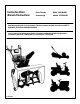
Instruction Book Manuel d’instructions Snow Thrower Model 629108x84B chasse−neige modèle 629108x84B Read and keep this book for future reference. This book contains important information on SAFETY, ASSEMBLY, OPERATION, AND MAINTENANCE. Lisez et conservez ce manuel pour référence. Ce manuel contient des informations importantes concernant la SECURITE, LE MONTAGE, L’UTILISATION ET L’ENTRETIEN.
NOTE: This unit is equipped with an internal combustion engine and must not be used on or near any unimproved forest-covered, brush-covered or grass-covered land unless the engine’s exhaust system is equipped with a spark arrester meeting applicable local or state laws (if any). If a spark arrester is used, it must be maintained in effective working order by the operator. In the State of California, the above is required by law (Section 4442 of the California Public Resources Code).
1 17 6 5 9 2 1 10 11 2 8 3 18 4 2 14 12 13 16 7 1 15 17 7 4 1 3 2 12 18 1 1 3 9 10 11 5 7 4 6 16 5 1 15 6 2 6 7 5 F-041030L 19 3
7 8 4 7 2 11 9 10 10 6 8 5 9 10 4 2 3 1 4 1 3 2 1 11 2 F-041030L 4 5 6
13 12 5 2 6 1 1 1 2 3 5 14 6 5 15 1 “A” 3 1 1 7 1 16 1 17 6 5 4 2 1 8 3 6 F-041030L 5 7
18 15 13 19 9 10 12 3 4 16 13 17 2 14 18 1 11 20 21 24 23 22 22 21 6 3 2 5 8 4 5 3 F-041030L 6
23 24 2 4 3 “A” 25 4 6 5 8 4 26 27 2 3 5 3 4 6 4 F-041030L 7
29 28 3 12 11 11 2 3 15 10 30 31 11 13 16 17 16 7 14 17 8 7 19 F-041030L 13 20 8 7
32 2- 9524 F-041030L 2- 3943 2 - 73826 9
ENGLISH CONTENTS Murray, Inc. warrants to the original purchaser that this unit shall be free from defects in material and workmanship under normal use and service for a period of Two (2) Year from the date of purchase; however, this warranty does not cover engines, accessories (such as electric starters) and Normal Wear Parts (except as noted below) as the companies that manufacture these items furnish their own warranties and provide service through their authorized field service facilities.
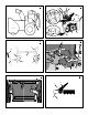
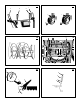
ENGLISH INTERNATIONAL PICTORIALS IMPORTANT: The following pictorials are located on your unit or on literature supplied with the product. Before you operate the unit, learn and understand the purpose for each pictorial. 33 Safety Warning Symbols DANGER Thrown Objects. Keep Bystanders Away. DANGER Thrown Objects. Keep Bystanders Away. WARNING Hot Surface STOP DANGER Avoid Injury From Rotating Auger. Keep Hands, Feet And Clothing Away. IMPORTANT Read Owner’s Manual Before Operating This Machine.
ENGLISH Safe Operation Practices for Snow Throwers As Recommended By: American National Standards Institute. IMPORTANT: Safety standards require operator presence controls to minimize the risk of injury. Your snow thrower is equipped with such controls. Do not attempt to defeat the function of the operator presence control under any circumstances. 7. Never attempt to make any adjustments while the engine (motor) is running (except when specifically recommended by manufacturer). Training 9.
ENGLISH ASSEMBLY Read and follow the assembly and adjustment instructions for your snow thrower. All fasteners are in the parts bag. Do not discard any parts or material until the unit is assembled. WARNING: Before doing any assembly or maintenance to the snow thrower, remove the wire from the spark plug. 5. 6. NOTE: In this instruction book, left and right describe the location of a part from the operator’s position behind the unit. 7. NOTE: Torque is measured in foot pounds (metric N.m).
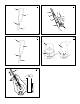
ENGLISH Traction Drive Lever (1) - Select the forward or reverse direction of travel. Crank Assembly (2) - Changes the direction of the discharge chute. Discharge Chute (3) - Changes the distance the snow is thrown. Remote Chute Control Lever (17) - Control the distance the snow is thrown. Auger Drive Lever (5) - Starts and stops the auger and impeller (snow gathering and throwing). 3. (Figure 2) To stop the engine, push the throttle control lever (13) to off and remove the ignition key (8).
ENGLISH 9. Push the primer button (9). Every time you push the primer button (9), wait two seconds. For the number of times required to push the primer button (9), see the engine manufacturer’s instructions. 10. (Electric Start) Push on the electric start button (10) until the engine starts. Do not crank for more than 10 seconds at a time. The electric starter is thermally protected.
ENGLISH MAINTENANCE CHART CUSTOMER RESPONSIBILITIES SERVICE RECORDS Fill in dates as you complete regular service.
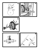
ENGLISH How To Adjust The Height Of The Skids (Figure 2) This snow thrower is equipped with two height adjustable skids (7). These skids elevate the front of the snow thrower. For normal hard surfaces, such as a paved driveway or walk, adjust the skids as follows. 1. Put the snow thrower on a level surface. 2. Make sure both tires are equally inflated. The correct air pressure is 14 PSI (1 BAR) to 17 PSI (1.25 BAR). Do not exceed the maximum amount of air pressure shown on the side of the tire. 3.
ENGLISH 9. (Figure 19) Remove the old auger drive belt (4) from the auger drive pulley (10). Replace the auger drive belt (4) with an original factory replacement belt available from an authorized service center. 10. Install the new auger drive belt (4) onto the auger drive pulley (10). NOTE: To assemble the auger housing (22) to the motor box (23), have someone hold the auger clutch lever in the ENGAGED position.
ENGLISH 20. (Figure 28) Install the right wheel (10) to the axle (11) with the fasteners removed earlier. 21. Connect the spark plug wire. How To Replace the Auger Shear Bolt The augers are secured to the auger shaft with special shear bolts. These shear bolts are designed to break and protect the machine if an object becomes lodged in the auger housing. Do not use a harder bolt as the protection provided by the shear bolt will be lost.
FRANÇAIS SOMMAIRE INFORMATIONS SUR LE PRODUIT INFORMATIONS DESTINEES AU PROPRIETAIRE PICTOGRAMMES INTERNATIONAUX MONTAGE FONCTIONNEMENT MAINTENANCE TABLEAU DE DEPANNAGE 20 20 21 23 24 26 30 GARANTIE LIMITEE DE DEUX ANS Murray, Inc.
FRANÇAIS PICTOGRAMMES INTERNATIONAUX IMPORTANT : les pictogrammes suivants sont situés sur votre appareil ou dans la documentation ci-jointe. Avant de vous servir de la tondeuse, apprenez à reconnaître chaque pictogramme. 34 Symboles de signalisation de danger DANGER Projection d’objets. Eloigner tout spectateur. DANGER Projection d’objets. Eloigner tout spectateur.
FRANÇAIS REGLES DE SECURITE A SUIVRE POUR L’UTILISATION DES CHASSE-NEIGE SELON LES RECOMMANDATIONS DE L’AMERICAN NATIONAL STANDARDS INSTITUTE. IMPORTANT : les normes de sécurité requièrent des contrôles de la présence du conducteur pour limiter les risques de blessures. Votre chasse-neige est équipé de ces contrôles. Ne pas tenter de rendre la fonction de contrôle de la présence du conducteur inopérante quelles que soient les circonstances. 7.
FRANÇAIS MONTAGE Lire et suivre les instructions de montage et de réglage de votre chasse-neige. Toutes les attaches se trouvent dans le sac de pièces détachées. Ne jeter aucune pièce avant d’avoir monté la machine. DANGER : avant de monter le chasse-neige ou de procéder à son entretien, retirer le câble de la bougie. REMARQUE : dans ce manuel, la gauche et la droite désignent l’emplacement d’une pièce par rapport à la position du conducteur à l’arrière de la machine.
FRANÇAIS ant du moteur pour connaître le type de carburant et d’huile à utiliser. Avant d’utiliser la machine, lire les informations concernant la sécurité, le fonctionnement, l’entretien et le remisage. Important ! Avant de démarrer la machine : r r r Vérifier toutes les fixations. S’assurer que toutes les fixations sont solidement serrées. Les modèles à démarrage électrique ont été livrés avec le câble du démarreur branché sur le moteur.
FRANÇAIS (8) en lieu sûr. Le moteur ne peut pas démarrer sans la clé de démarrage (8). Démarrage du moteur (Figure 2) Modèles équipés d’un starter électrique REMARQUE : Un kit de starter électrique peut être rajouté aux moteurs à démarrage manuel. Les kits de starter électrique sont disponibles dans votre centre de maintenance agréé le plus proche. DANGER : Le starter est équipé d’une rallonge trifilaire conçue pour fonctionner avec du courant domestique de 120 volts A.C.
FRANÇAIS TABLEAU DE MAINTENANCE RESPONSABILITES DE L’ACHETEUR REGISTRE DES OPERATIONS D’ENTRETIEN Complétez les dates au fur et à mesure des opérations d’entretien régulier effectuées.
FRANÇAIS Pièces à ne pas lubrifier (Figure 15) 1. Ne pas graisser l’arbre hexagonal et le pignon (6). Toutes les bagues et les roulements sont lubrifiés à vie. Pour le remisage, verser une légère quantité d’huile moteur 5W-30 sur un chiffon et essuyer l’arbre hexagonal et le pignon (6) afin d’éviter la rouille. 2. Si la graisse entre en contact avec le disque de friction de caoutchouc (3) ou le plateau d’entraînement du disque (1), le disque de friction de caoutchouc (3) peut être endommagé.
FRANÇAIS 7. Vérifier le réglage du câble d’entraînement de la fraise. Voir “Vérification et réglage des câbles” dans la section Entretien de ce manuel. 8. Rebrancher le fil de la bougie. Courroie d’entraînement des roues La courroie d’entraînement des roues est soumise à la pression constante d’un ressort et n’exige aucun réglage. Si la courroie d’entraînement des roues patine, remplacer la courroie. Voir “Remplacement des courroies” dans la section Entretien de ce manuel.
FRANÇAIS 2. Débrancher le fil de la bougie. 3. (Figure 22) Desserrer les boulons (3) sur chaque côté du panneau ventral (2). 4. Retirer le panneau ventral (2). 5. (Figure 2) Mettre la manette d’accélération (6) à la vitesse la plus basse. 6. (Figure 24) Remarquer l’emplacement de la roue de friction (4). La distance “A” correcte entre le côté droit de la roue de friction (4) et l’extérieur du carter du moteur est la suivante : Taille du pneu Distance “A” 12 et 13 pouces de 4à 1/8” (10.5 cm.
FRANÇAIS Remplacement des pièces détachées Le remplacement de pièces détachées est montré soit au dos de ce manuel, soit dans un manuel séparé de pièces de rechange. Il est vivement recommandé de n’utiliser que des pièces autorisées par le fabricant ou approuvées. La lettre placée à la fin du numéro de la pièce vous signale le type d’affinage pour la pièce, C pour le chrome, Z pour le zinc, PA pour une pièce achetée. Il est important de le joindre lors de la commande d’une pièce.
Parts List − Model 629108x84B Liste de pièces − Modèle 629108x84B F-041030L 31
MODEL 629108x84B REPAIR PARTS ENGINE 16 1 2 5 17 18 20 12 22 25-2 24 ÁÁ 13 25-1 Á 10 14 15 6 4 25-3 7 23 11 8 26 25-2 25-4 9 Ref. Drive Page 3 Ref. Auger Housing Page Key No. Part No. 1 2 3 4 5 6 7 8 9 10 11 12 13 14 15 * 6219 * 002x97 028x76 710026 1501109 710247 71063 71015 579932 585416 1501112 YZ 1501065 71060 910828 Description Key No. Part No.
MODEL 629108x84B REPAIR PARTS GEAR CASE 340 326 320 321 306 322 310 323 324 327 330 316 312 311 305 311 301 304 313 312 315 314 310 300 303 Key No. Part No. Description Key No. Part No. Description 300 896 CASE, GEAR, RH 316 73905 KEY, WOODRUFF #91 301 895 CASE, GEAR, LH 320 53737 RING, QUAD 0.924 ID 303 910828 SCREW, 5/16-24 x 1.00 321 583126 BEARING, FLANGE 304 71100 NUT, 5/’16-24 322 48275 WASHER, FLAT 305 330434 SCREW, 5/16-24 x 1.
MODEL 629108x84B REPAIR PARTS FRAME 160 106 162 105 167 108 111 Ref. Engine Page Ref. Auger Housing Page 167 162 Ref.
MODEL 629108x84B REPAIR PARTS FRAME Key No. Part No. F-041030L Description 90 1501055E701 COVER, BOTTOM 91 310169 SCREW, 1/4-20X .63 103 1501226 YZ IDLER ASSEMBLY, AUGER 105 711682 PIN, HAIR .38DIAX1.64LG 106 761761 PIN, CLEVIS 3/16” DIA 107 165x159 SPRING, TENSION 108 761675 YZ ASSY., SPRING ATTACH 110 585781 BOLT, 3/8-16X1.25 CARR. 111 711617 WASHER, FLAT 122 25x020 SCREW, TAP 5/16-18 X .50 123 25x021 SCREW, TAP 5/16-18 X .
MODEL 629108x84B REPAIR PARTS DRIVE 229 Ref. Shift Yoke Page Ref. Frame Page Ref. Wheel Page 200 221 225 223 Ref. Wheel Page 226 206 227 201 229 234 232 236 204 204 234 203 203 230 238 215 220 218 Ref. Wheel Page 207 215 213 213 Ref.
MODEL 629108x84B REPAIR PARTS DRIVE Key No. Part No. F-041030L Description 200 1501092 YZ LF AXLE, SWING PLATE YZ 201 579851 CHAIN, ROLLER #420x19.00 203 334163 BEARING AND RETAINER, ASSY 204 579858 WASHER 206 25x020 SCREW, TAP 5/16-18x0.5 207 1501100 ASSY, HEX SHAFT 208 579868 CHAIN, ROLLER #420x18.
MODEL 629108x84B REPAIR PARTS AUGER HOUSING 484 482 499 500 490 527 480 485 522 491 523 511 525 493 541 527 522 523 520 524 Ref.
MODEL 629108x84B REPAIR PARTS AUGER HOUSING Key No. Part No. F-041030L Description 480 583146 PULLEY, 4L 8.40 OD 482 2001022 KEY, SQUARE 3/16 X 3/4 484 15x112 NUT, 1/2-20 485 1501158 SPACER, FRICTION PULLEY 490 582957 YZ RETAINER, BALL BRNG 491 1501389 BEARING, BALL 493 001X92 BOLT, HEX 5/16-18X .50 499 710026 NUT, 5/16-18 HEXWDFLLK 500 1501121E700 HOUSING, ASSY 510 760655E701 BLADE, SCRAPER 511 340720 BOLT, 5/16-18X.
MODEL 629108x84B REPAIR PARTS CONTROL PANEL ASSEMBLY 765 784 774 778 REF. HANDLE PAGE 772 773 768 761 768 773 764 781 789 760 770 766 805 806 809 808 810 812 814 Key No. Key No. 813 Part No. Description Part No. Description 760 1501632 YZ HANDLE ASSY SPD CTRL 781 71071 FLATWASHER 761 302900 SCREW, 5/16-18X1.75 784 306689 GRIP, HANDLE 764 710026 NUT, 5/16-18 789 71081 PIN, COTTER 765 1501414E700 ASSY.
MODEL 629108x84B REPAIR PARTS HEADLIGHT Key No. F-041030L Part No.
MODEL 629108x84B REPAIR PARTS HANDLE 731 748 Ref. DETAIL “A” 730 756 762 762 742 764 729 755 741 720 762 761 761 762 Ref. CONTROL PANEL 728 727 726 725 724 765 750 723 726 727 743 725 DETAIL “A” Ref. Key #60 759 757 758 765 767 745 744 751 768 Ref.
MODEL 629108x84B REPAIR PARTS HANDLE Key No. Part No.
MODEL 629108x84B REPAIR PARTS CHUTE ROD 856 855 854 862 855 Ref. Handle Assy 860 863 861 865 864 870 864 867 852-9 852-5 852-8 852-13 852-10 Ref.
MODEL 629108x84B REPAIR PARTS CHUTE ROD Key No. Part No.
MODEL 629108x84B REPAIR PARTS DISCHARGE CHUTE 582 584 585 580 586 604 587 588 600 Pop Rivets 602 603 601 610 609 606 611 607 607 Ref.
MODEL 629108x84B REPAIR PARTS DISCHARGE CHUTE Key No. F-041030L Part No. Description 580 761168E701 CHUTE, UPPER W/REMOTE 582 578088 SCREW, 5/16-18 X.75 584 71038 NUT 585 578088 SCREW, 5/16-18 X.
MODEL 629108x84B REPAIR PARTS REMOTE CONTROL 995 994 Ref. Control Panel Page 980 Ref. Engine Page (Engine Mount Bolt) 965 973 975 975 969 981 974 967 971 968 970 972 F-041030L 48 Ref.
MODEL 629108x84B REPAIR PARTS REMOTE CONTROL Key No. Part No. F-041030L Description 965 318468 TENSION SPRING 967 310088 BOLT 968 73787 FLATWASHER 969 15x143 NUT 970 313676 SCREW 971 306447 YZ BRACKET, CABLE CHUTE 972 71391 NUT 973 1001221 TRIM STRIP 974 760113 TIE, CABLE 975 1501393 ASSY, CHUTE DEF.
MODEL 629108x84B REPAIR PARTS WHEELS 679 678 673 675 671 654 650 678 655 652 676 Ref. Drive Page 655 671 673 653 680 Key No. Part No. F-041030L Description 650 1501563 SHAFT, AXLE 652 1501089 SPRKT & HUB 653 01x193 SCREW, 1/4-20 x 1.75 654 15x145 NUT, 1/4-20 HEX NYLOCK 655 1501114 BEARING, AXLE 671 712120 FLATWASHER 673 1501138 BUSHING, WHEEL 675 1501818 TIRE & RIM, RIGHT 676 577015 SCREW, 1/4-20X1.
F-041030L 51
MURRAY, INC. LAWN MOWER CENTRAL PARTS DISTRIBUTORS DISTRIBUTEURS RÉGIONAUX DE PIÈCES MURRAY, INC. BILLIOU’S, INC. FRANK EDWARDS CO. GULF COAST ENGINE, INC. 1343 South Main St. Porterville, CA. 93257 (559) 784−4102 1−877−245−5468 FAX 1−800−226−7337 www.billious.com Arizona, California, Hawaii, Nevada 3626 Parkway Blvd.