Murray Electrical Products SPEEDFAXTM 2017 Section Siemens would like to welcome the Murray Electrical Products into the Speedfax. The Murray Electrical Products catalog and Siemens Speedfax has been combined for our customer’s convenience. All of the Murray-branded product is located in section 3 so Murray customers will not have to sort thru the entire Speedfax to find associated products. Customers can now select Murray and Siemens products without having to flip between catalogs.
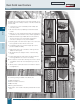
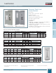
Revised on 11/01/17 Rock Solid Load Centers Features MURRAY 3 The Murray Rock Solid Load Center is the highest quality, most versatile design in the industry. Features on the Rock Solid Load Center include: 1. “Swiss Cheese” style neutral bars provide multiple 1/0 connection points. 1 2. All units include factory installed ground bar and isolated neutral. 3. With the use of the included bonding strap, ground bars and neutral bars can be bonded for service entrance applications. Load Centers 4.
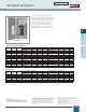
Revised on 11/01/17 Rock Solid Load Centers f Main Lug Only, 1Ø, 65,000 AICa, Main Lug Panels 3-Wire 120/240V AC or 208Y/120V AC, Insulated and Bonded Split Neutrals Load centers on this page through 225 amp feature a split neutral insulated bars. For service entrance applications, install bonding strap, and use both bars for neutral and ground conductors.
Revised on 11/01/17 Rock Solid Load Centers Main Breaker, 1Ø, 22,000 AIC Load centers on this page through 200 amp feature a new split neutral with one bonded and one insulated bar. For service entrance applications, install bonding strap, and use both bars for neutral and ground conductors. For non service entrance applications, do not install bonding strap and use insulated bar for neutral conductors and bonded bar for ground conductors.
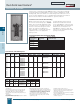
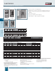
Load Centers Generator Ready, Riser, & 400A Load Centers Generator Ready Load Center Features n n n n n n n n NEMA 1 Generator Ready NEMA 3R Generator Ready n Branch Circuits Indoor Enclosure - NEMA Type 1 Load Centers Generator Ready Load Centers (1phase) Outdoor Enclosure - NEMA Type 3R Dimensions (inches) Dimensions Amp Rating No. of No. of Spaces Circuits Catalog Number H W D Catalog Number H W D 200 30 42 LC3042B1200GEN 42 14.25 4 LW3042B1200GEN 42.00 14.63 4.
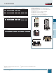
Load Centers Circuit Breaker Enclosures & Small Load Centers n n n n n n LC004NS MURRAY 3 LC002GS Ideal for Narrow stud applications Eliminated “notching” needed for standard Load Centers Outdoor Load Center with factory installed Ground Fault Breaker Two extra circuits Factory installed feed-through lugs Main Breaker or Main Lug panels available Load Centers Spa Panels Ampere Rating 125 125 No. of Spaces 2 2 Max.
Load Centers Load Center OEM Interiors 1Ø: Small Circuit Main Lug Interiors Dimensions Circuits Spaces Height Width Amps Catalog Numbera I0204ML1125 2 2 5.06 2.12 60 I0303ML3100 3 3 5.06 3.12 60 I0408ML1125 4 8 4.51 6.61 125 I0816ML1125CU 8 16 6.19 6.81 125 I0816ML1125CUSP 8 16 6.19 6.81 125 I0202L1200 4 4 3.88 7.13 200 Small circuit Interiors The small circuit interiors are ideal for OEM applications requiring only a few circuits.
Load Centers Electricenter Accessories Hubs Catalog Number ECHS075 ECHS100 ECHS125 ECHS150 ECHS200 ECHS250 Description 3⁄4” Hub 1” Hub 11⁄4” Hub 11⁄2” Hub 2” Hub 21⁄2” Hub Pack Quanity 10 10 10 10 10 10 Catalog Number Description For use on MP-T, MP-HT, & MP-MT breakers in Rock Solid Load Centers For use on MP-T, MP-HT, & MP-MT breakers in 2–8 circuit Load Centers For use on MD-T, MD-HT, & MD-MT breakers on old style (pre 2003) load centers (12–42 circuit) For use on MP-T, MP-HT, & MP-MT breakers (15–
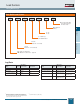
Load Centers Catalog Number Logic Rock Solid Load Centers LC 30 40 L 1 200 CU CU = Copper Bus Bar T = Feed Thru Lugs P = Value Pack 3 Main Ampere Rating MURRAY 1 = 1Ø 3 = 3Ø L = Main Lug B = Main Breaker Load Centers Circuits (max. No. of circuits) Spaces (max. No.
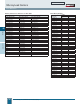
Revised on 11/01/17 Murray Load Centers Cross References Murray 3-Phase Cross Reference to New SKUs Height Load Centers MURRAY 3 (See Section 1 for full offering) Legacy Murray SKU ES™ Series Part No. PL™ Series Part No.
Knockout Diagrams Rock Solid Load Centers (including Generator Ready) Indoor Main Breaker and Main Lug Enclosures Outdoor Main Breaker and Main Lug Enclosures 4 K.O.s For 0.25” Conduit 2 K.O.s For .038”, 0.5”, 0.75”, 1”, 1.25” Conduit 12 K.O.s For .038”, 0.5”, 0.75” Conduit MURRAY 10 K.O.s For 1”, 1.25”, 2”, 2.5” Conduit 12 K.O.s For 0.5”Conduit 8 K.O.s For 0.5, 0.75” Conduit 52 K.O.s For 0.5”Conduit 4 K.O.s For 1”, 1.
Knockout Diagrams Indoor and Outdoor Enclosures 400A Outdoor 400A Indoor E E B B B B B B GG GG D W D W E E HV HV B B B B B B L Load Centers MURRAY 3 L B B B B B B E E GG GG B B B B B B B B B B B B E E 8 Circuit Outdoor E E B B B B GG GG E E B B 4 Circuit Outdoor D W D W HS HS L M M M B M B L C C C Knockout Code—Conduit Sizes g = 1⁄4 A = 1⁄2 B = 1⁄2, 3⁄4 C = 1⁄2, 3⁄4, 1 D = 1⁄2, 1 E = 1⁄2, 3⁄4, 1, 11⁄4 F = 1⁄2, 11⁄4, 11⁄2 G = 3⁄4 H = 3⁄4, 1 J = 3⁄4, 1, 11⁄4 K = 3⁄4,
Circuit Breakers Arc-Fault Circuit Interrupters (AFCI) Arc-Fault Circuit Interrupters (AFCI) AFCI’s detect arcing faults (an unintentional arcing condition in a circuit) that standard circuit breakers are unable to detect.
Circuit Breakers Full Size (1" per Pole) with INSTA-WIRE Continuous Current Rating @ 40° C Type MP-T Type MP-HT Type MP-MT 10,000A IR 22,000A IR 65,000A IR Catalog Number e Catalog Number Catalog Number MP110 MP115d MP120d MP125 MP130 MP135n MP140 MP145n MP150 MP160n MP170n — MP115KHd MP120KHd MP125KHn MP130KH MP135KHn MP140KH MP145KHn MP150KH MP160KHn MP170KHn f — MP115KMnd MP120KMnd MP125KMn MP130KMn MP135KMn MP140KMn MP145KMn MP15KKMn MP160KMn MP170KMn MP215KH MP220KH MP225KHn MP230KH MP23
Circuit Breakers Duplex, Triplex and Quadplex Plug-in Breakers Duplex Circuit Breakers Breaker Type MH-T 1-Pole 10K AIC 120V AC MH-T Duplex Ampere Rating Catalog Number 15–15 MP1515 15–20 MP1520 20–20 MP2020 20–30 MP2030 15–30 MP3015n 30–30 MP3030 SHIPPING: 12 per carton, (Wt. 4.8 lbs.) Catalog Number MP1515Na MP1520Nna MP2020Na MP2030Nna MP3015Nna MP3030Nna Triplex Circuit Breakers MH-T 2-Pole 10K AIC 120/240V AC Inner Poles Common Trip.
Circuit Breakers Circuit Breaker and Surge Protective Device (SPD) Features Circuit Breaker and Surge Protective Device (SPD) 2 inch wide plug-on design — Includes (2) 1 Pole circuits breakers — No loss of load center spaces n Easy to install and perfect for retrofit n LEDs provide protection status n MURRAY 3 Benefits By installing a Siemens Circuit Breaker and Surge Protective Device (SPD) in the load center of the residence, surge protection is provided for all branch circuits.
Circuit Breakers Special Application Breakers HID Lighting For high-intensity discharge lamp loads having in-rush currents above the instantaneous trip setting of a standard breaker. Breaker Type MP-T 1-Pole 120V AC QP Figure 1 Figure 1 Complete Breaker UL Unenclosed Ampere Rating Catalog Number 15 20 30 15 20 30 MP115HID n a MP120HID n a MP130HID n MP215HID n MP220HID n MP230HID n 3 2-Pole 120/240V AC Wiring Diagram Molded case non-automatic switch does not provide overload protection.
Circuit Breakers Type MSQ, 3/4 Inch Plug-In Breakers Features • 3/4" format. • HACR Rated. • UL Classified for use in certain Square Db load centers. Type MSQ Circuit Breakers MURRAY 3 The Type MSQ circuit breaker line is available in 1-pole and 2-pole common trip versions listed on this page. The circuit breakers are UL Classified and UL Listed. All MSQ breakers are supplied with load side connectors suitable for 60/75°C wire and are calibrated for 40°C maximum ambient applications.
Circuit Breakers Main and Branch Circuit Breakersa MPD2150 MPD2175n MPD2200 MPD2150KH MPD2175KH n MPD2200KH MPD2150KM MPD2175KMn MPD2200KM MPD2150R MPD2175R n MPD2200R MPD2150RH MPD2175RH n MPD2200RH MPD2150RM MPD2175RMn MPD2200RM Breaker Type Ampere Rating Catalog Number UL Interrupting Ratings (kA) M1e 100 MBK100M MD-Tc 2-Pole 120/240V AC MD-HTc 2-Pole 120/240V AC MD-MTc 2-Pole 120/240V AC M2e 2-Pole 120/240V AC Breaker Type ED-Af 3-Pole 240V AC MPPg 2-Pole 120/240V AC MPP-HTg 2-Po
Circuit Breakers Circuit Breaker Accessories Circuit Breaker Accessories Catalog Number For Use With Breaker Type Number of Poles Standard Package Padlocking Device For locking breaker in “OFF” position.
Circuit Breakers Circuit Breaker Accessories Padlocking Device ECPLD1 ECQLD3 3 ECQLD4 ECQTH4 MURRAY ECPLD1R/2R/3R (Single pole pictured. 2-/3-pole available) ECPLD2 Handle Blocking Device Handle Tie ECQL1 ECBX231M Main Breaker Retainer ECMBR2 Circuit Breakers ECQTH3 ECQTH2 Mechanical Interlock ECQML12 Siemens Industry, Inc.
Circuit Breakers Line Diagrams 1-Pole 2-Pole 3-Pole 3" 23/8" MURRAY 3 31/8" Type MH-T Type MP-GT, MP-HGT, MP-ET, MP-HET Circuit Breakers Type MP-T, MP-HT, MP-MT Type M1 Type MD-TR, MD-HTR, MD-MTR Type M2 Type MPP-T, MPP-HT, MPP-MT, MPP-PT a All standard circuit breakers are calibrated to 40°C maximum ambient application. 3-22 Siemens Industry, Inc.
Circuit Breakers Lug Data Circuit Breaker Type Circuit Breaker Ampere Rating Cables Per Connector Connector Wire Range LOAD SIDE MP-T, MP-HT, MP-MT #16–#14 CU 15–35 1 1 #14–#16 AWG Cu #14–#16 AWG Al 40–50 1 1 #8–#6 AWG Cu #8–#4 AWG Al 55–125 (exception: 1 & 2-pole MP-T at 55-60) 1 1 #8-#2/0 Cu #8-#2/0 Al MP-T 1 & 2-Pole ONLY 55–60 1 #6-#4 AWG Cu-Al (#3 requires AWG MP-HT or MP-MT) MH-T 15–35 1 1 #14–#8 AWG Cu #12–#8 AWG Al 40 1 #8 AWG CU-Al 40–50 1 1 #8–#6 AWG Cu #8–#4 AWG Al
Combination Meter Sockets Catalog Number Logic New Style Combination Meter Sockets JA 30 40 B 1 200 S E C W MURRAY 3 Main Ampere Rating 1 = 1 Phase 3 = 3 Phase L = Main Lug B = Main Breaker Circuits (max. No. of circuits) Spaces (max. No. of 1" breakers) Combination Meter Sockets JC = Meter Main JA = Meter Load Center Combination 3-24 Siemens Industry, Inc.
Combination Meter Sockets Meter Load Center Combinations Meter Mains Introduction Meter Load Center Combinations Meter Mains Meter Load Center Combinations Side-By-Side This section includes 4 product categories, which each include Meter their Mains own set of featured products: Over-Under Combo Meter Mains Side-B Over-Under EUSERC Meter Mains Murray Meter Mains are UL Listed and available from 100A to 400A services.
Meter Load Center Combinations Meter Mains Meter Load Center Combinations Meter Mains Meter Mains Side-By-Side Over-Under Combo Side-By-Side Meter Mains, 100A-400A Over-Under Combo Side-By-Side Over-Under Side-By-Side Over-Under EUSERC Meter Mains Side-By-Side 14” Side-By-Side Side-By-Side Full Load Center EUSERC EUSERC Side-By-Side 14” Side-By-Side 400A EUSERC Side-By-Side Full Load Center Side-By-Side 400A JC0202B1125RJB meter mains, side hinge door Side-By-Side 400A Meter Load Ce
Meter Load Center Meter LoadCombinations Center Combinations Meter Mains Meter Mains Meter Load Center Combinations Side-By-Side Side-By-Side Combo Over-UnderOver-Under Combo Side-By-Side Side-By-Side Over-Under Over-Under Over-Under Construction Meter Load Center Combinations, 150A-200A EUSERC Meter Mains EUSERC Meter Mains Side-By-Side 400A EUSERC EUSERC Side-By-Side 14” Side-By-Side Full Load Center Side-By-Side 400A Side-By-Side 14” Side-By-Side Full Load Center Side-By-Side 400A Over-Un
Meter Load Center Combinations Side-By-Side Meter Mains Meter Load Center Combinations Side-By-Side Over-Under Meter Load Center Combinations Over-Under Combo Meter Mains EUSERC Meter Mains Side-By-Side Over-Under Combo Side-By-Side Meter Load Center Combinations, 100A-400A Over-Under Combo EUSERC EUSERC Meter Mains Meter Load Center Combinations Side-By-Side 400A Side-By-Side Side-By-Side Over-Under Side-By-Side Over-Under EUSERC Meter Mains Figure 1 EUSERC Meter Mains EUSERC Meter L
EUSERC Meter Load Center Combinations Side-By-Side 14” Over-Under 14”Side-By-Side EUSERC EUSERC EUSERC EUSERC EUSERC EUSERC Meter Mains EUSERC EUSERC Meter Mains Side-By-Side 400A Side-By-Side Full Load Center Side-By-Side 400A EUSERC Side-By-Side Construction Meter Mains, 125A-400A n n n n n n n n n n n Side-By-Side 14” Figure 2 EUSERC Side-By-Side Full Load Center Side-By-Side 400A MURRAY n Over-Under 14” Figure 1 3 n UL listed For overhead and underground feed applications Desi
EUSERC Meter Load Center EUSERC Meter LoadCombinations Center Combinations n n 200 12 12 200 20 40 30 42 Combination Meter Sockets 200 225 UG UG UG EUSERC EUSERC EUSERC Over-Under 14” Side-By-Side 14” EUSERC EUSERC EUSERC EUSERC EUSERC 30 40 40 Surface Side-By-Side 14” No. of Spaces No.
EUSERC Meter Mains Side-By-Side EUSERC EUSERC EUSERC Meter Load Center Combinations Side-By-Side 400A EUSERC Side-By-Side Construction Meter Load Center Combinations, 400A n n n n Side-By-Side Over-Under Combo Over-Under Combo Side-By-Side Over-Under EUSERC Meter Mains EUSERC EUSERC EUSERC Meter Load Center Combinations Side-By-Side 400A Side-By-Side EUSERC Meter Load Center Combinations Side-By-Side 400A EUSERC Meter Load Center Combinations Side-By-Side Side-By-Side Side-By-Side 1
Combination Meter Sockets Electricenter Accessories Catalog Number EC5J-2 RX Type Hub JC0406L1200H JC0406L1200RH JC0406L1200RHJB SX001M HS Type Hub EMC5J MURRAY 3 SX006M Interchangeable Hubs Conduit Size (Inches) Lbs. Catalog Number RX Type Hubs ⁄4 EC38594 1 EC38596 3 1 1 ⁄4 EC38597 11⁄2 EC38598 2 EC38599 Grounding Bars (AI/Cu — except where noted) Grounding bars are for use where grounding of electrical outlets and devices is by means of conductors.
Group Metering: NYC Gangable Metering General Information Product Descriptions Murray New York City Apartment Metering is a versatile, unassembled modular metering product comprised of separate modules that may be assembled to produce a variety of configurations. Only those standard modules shown in this publication will be sold. Installation instructions are shipped with the product.
Group Metering: NYC Gangable Metering General Information MURRAY 3 Getting Started Before ordering components, the following should be known: n Installation instructions are shipped with the product n Number of meter positions n Amp rating of each meter position n Voltage and phase of incoming line n Line conductor size and quantity n Vertical and horizontal space limitations, if any Meter stacks are 10” wide and are 10” high for each meter position, or blank position.
Group Metering: NYC Gangable Metering Meter Stack Selection Use Selection Chart #1 and Specification Chart #1 Knowing the number of meter positions, and the height and width requirements, select quantity and catalog number of stacks from Selection Chart #1. The height dimension in this chart includes line and breaker troughs. For specs, refer to Specification Chart #1. Specification Chart #1—Meter Stacks 300V AC max.
Group Metering: NYC Gangable Metering MURRAY 3 Trough & Phase Block Selection Line Troughs Breaker Troughs Phase Blocks (Use Selection Chart #2 and Specification Chart #2) (Use Selection Chart #2 and Specification Chart #3) (Use Selection Chart #2 and Specification Chart #4) Knowing the number of meter stacks, (not meter positions!) and the height and width requirements, select quantity and catalog number of stacks from Selection Chart #2.
Group Metering: NYC Gangable Metering Terminals & Accessories Line Trough Spacer Kits (Use Selection Chart #2 and Specification Chart #6) (Use Selection Chart #2 and Specification Chart #6) When more than one line trough is needed to support the number of meter stacks on a job, or when a line trough spacer is required, coupling straps are required to connect the troughs. Use Selection Chart #2 footnotes 3 and 4 to determine quantity of coupling kits required.
Safety Switches General Description HHN426N HUN361AW MURRAY 3 GHN424NW Passed The Test of Time Horsepower Ratings Fuse Interchangeability All Murray safety switches have passed rigid testing requirements to assure reliable performance. In addition to tests designed and conducted during the development and manufacturing processes, switches have performed successfully in tests witnessed by Underwriters’ Laboratories.
Safety Switches Technical Information General Duty Switches; Prefix “G” General duty switches are available in indoor TYPE 1 and outdoor TYPE 3R enclosures. Enclosures can be locked closed and operating handles can be locked “off”. Series “G” switches have a quick-make, quick-break mechanism. Fusible switches are available in 1 pole S/N, 2 pole S/N and 3 pole S/N configurations. Non-fusible switches are available in 3 pole configurations. General duty switches are limited to 240V AC, 200 Amps max. rating.
Safety Switches General Duty Compact — 10,000 Amp Withstand Plug Fuse Type 1 & Type 3R GU221 MURRAY 3 GP321N General Duty Compact Safety Switches Indoor TYPE 1 Symbol Catalog Number Fuse Type Std. Pkg. Horsepower Rating Outdoor TYPE 3R Approx. Catalog Wgt. Lbs. Number Std. Pkg. Single Phase Three Phase 120V AC Approx. Wgt. Lbs. Hub Std 240V AC Max a Std 240V AC Max a Std Max a 30 AMP FUSIBLE 1 POLE 2 WIRE S/N 120V AC (INSULATED GROUNDABLE NEUTRAL) Fig-1 GP211N Plug 10 33.
Safety Switches General Duty — 30–200 Amp, 10,000 & 100,000 Amp Withstand Cartridge Fuse Type 1 & Type 3R GUN322 GHN321N GHN423NW 3 MURRAY Switch Selection with Class “H“ Fuse Holders 30–600 Amps (Convertible to Class “R“)a Indoor TYPE 1 Symbol Amps Std. Catalog Number Pkg. Horsepower Rating Outdoor TYPE 3R Approx. Wgt. Lbs. Catalog Number Std. Pkg. Single Phase Approx. Wgt. Lbs.
Safety Switches Heavy Duty — 240V AC, 10,000 & 200,000 Amp Withstand Cartridge Fuse Type 1 & Type 3R HHN323NW HHN421NW MURRAY 3 HHN422N Switch Selection with Class “H“ Fuse Holders (Convertible to Class “J“, “R“ or “T“)a Indoor TYPE 1 Symbol Amps Std. Catalog Number Pkg. Horsepower Rating Outdoor TYPE 3R Approx. Wgt. Lbs. Catalog Number Std. Pkg. Single Phase Approx. Wgt. Lbs.
Safety Switches Heavy Duty — 600v AC, 10,000 & 200,000 Amp Withstand Cartridge Fuse Type 1 & Type 3R HHN361AW HHN364 Plus Neutral HN64M 3 MURRAY Switch Selection with Class “H“ Fuse Holders (Convertible to Class “J“, “R“ or “T“)a Indoor TYPE 1 Outdoor TYPE 3R Symbol Catalog Amps Number Approx. Wgt. Lbs. (Std. Pkg. 1) Catalog Number Horsepower Rating Approx. 480V AC 1Ø Wgt. Lbs. (Std. Pkg.
Safety Switches Heavy Duty—600V AC, 10,000 & 200,000 Amp Withstand Cartridge Fuse Industrial Type 12 & 4X Switch Selection With Class “H” Fuse Holders (Convertible To Class “J”, “R” or “T”)a Industrial Type 12 Horsepower Rating HUN361AJ Symbol Amps Catalog Number Approx. Wgt. Lbs. 480V AC 3Ø (Std. Pkg. 1) Std Max 600V AC 3Ø Std Max 250V DC 600V DC FUSIBLE 3 POLE 600V AC (NO NEUTRAL) cf 3 Fig-1 30 60 14.00 20.
Safety Switches VBII Type Double Throw Switches Type 1 & Type 3R Double Throw Switchesa Indoor TYPE 1 Symbol Amps Catalog Number Outdoor TYPE 3R Approx. Wgt. Lbs. Catalog Number Approx. Wgt. Lbs. Horsepower Rating Hub 1Ø 1Ø Std 3Ø Max 3Ø Std 250V DC Max NON-FUSIBLE 2 POLE 240V AC Fig-1 3 100 200 HDUN223 HDUN224 37.00 79.00 —6 HDUN224AW6 — 79.00 — ECHS — — 15 15 — — — — 20 40 38.00 HDHN321AW 39.
Safety Switches Protector-Lock® Switches Protector-Lock® Switches With Crouse-Hinds® Receptacles Industrial Type 12 Symbol Switch Amps Recept Amps Catalog Number Approx. Wgt. Lbs. (Std. Pkg. 1) Use Plug # b NON-FUSIBLE, 3 POLE 600V AC SWITCH (STYLE 2 RECEPTACLE, 4 WIRE, ONE WIRE GROUNDED) 60 60 HUN362CJ 29.00 APJ6485 3 Fig-2 Safety Switches MURRAY Figure 2 Accessories and Lug Data — See pages 3-47 and 3-48. Dimensions — See pages 3-50 and 3-51. aNot UL listed.
Safety Switches Accessories HT63M HR612M 3 HN612M MURRAY HA161234M Neutral Kitsa Standard Neutral Kits can be field installed in General and Heavy Duty Switches. Switch Ampere Rating Kit Catalog Number 30 GD 30 HD, 60 GD 60, 100 HD, 100 GD 200 W410190M HN612M HN623M HN64M HA261234M Class T Fuse Adapter Kitsc All 200A General Duty and 100-1200A Heavy Duty Switches are field convertible to accept Class T fuses.
Safety Switches Accessories & Lug Data Type VBII 3R Hubsa (60–600A GD 30–1200A HD) Conduit Size (Inches) Catalog Number Std. Pkg. Ship. Wgt. (Std. Pkg.) ⁄4 1 11⁄4 11⁄2 2 21⁄2 21⁄2 3 31⁄2 4 ECHS075 ECHS100 ECHS125 ECHS150 ECHS200 ECHS250 ECHV250 ECHV300 ECHV350 ECHV400 1 1 1 1 1 1 1 1 1 1 .50 .50 .50 .50 .50 .50 1.00 1.00 1.00 1.
Safety Switches Dimensions — Compact Switches, General Duty Switches E B or C A D E E G B or C G B or C A A F E B or C A F D F D G B or C A Type 1 or 3R 400-1200A Type VBII Type 4/4X or 12 30-200A Type VBII MURRAY G F D Type 1 or 3R 60-200A GD, 30-200A Type VBII 3 Type 1 or 3R 30A GD E F D G Type 4/4X or 12 400-600A Type VBII Safety Switch Dimensionsb Height Box Catalog Number A Width Depth With Door With Rain Shed Box With Handle Box With Handle B C
Safety Switches Dimensions — General & Heavy Duty Switches Safety Switch Dimensionsb Width Heightd GU221AW GU222AW GUN321 GUN321AW GUN322 GUN322AW GUN323 GUN323AW GUN324 GUN324AW HHN321N HHN321NW HHN322NW HHN323NW HHN324N HHN361AJ HHN361AW HHN362 HHN362AJ HHN362AW HHN363 HHN363AW HHN364 HHN364AW HHN421N HHN421NW HHN422N HHN422NW HHN423NW HHN424N HLN327N HLN328N HLN367 HLN367AW Box With Rain Shed A B C 8.07 8.07 7.97 8.07 11.11 11.11 21.95 21.95 29.90 29.90 14.26 14.39 16.26 21.95 29.90 14.27 14.
Safety Switches Dimensions — General & Heavy Duty Switches, Protector-Lock® Switches, Double Throw Switches Safety Switch Dimensionscd Height Box Catalog Number A Width Depth With Door With Rain Shed Box With Handle Box With Handle B C D E G Knockout Diagrama F 67.16 — 67.16 — 67.16 — 67.74 — 67.74 — 38.40 38.40 38.40 38.40 38.40 39.96 39.96 39.96 39.96 39.96 9.24 9.24 9.24 9.24 9.24 14.68 14.68 14.68 14.68 14.68 — — — — — HLN428NW HUN361 HUN361AJ 66.67 11.11 11.
Safety Switches Knockout Drawings S1 S2 S3 S2 S1 3 K.O.'s for Conduit 0.5-0.75-1 in. 10 K.O.'s for Conduit 0.5-0.75-1 in. 3 7 K.O.'s for Conduit 0.5-0.75-1 in. Removable plate covering HA Type Hub opening (Max. 1.25 Conduit) S5 S6 10 K.O.'s For Conduit 0.50, 0.75, 1 in. S5 S4 2 K.O.'s for Conduit 0.5-0.75 in. 2 K.O.'s for Conduit 0.5-0.75 in. 4 K.O.'s for Conduit 0.5-0.75 in. S4 Embossed .25 in. mounting holes (3 places) Embossed .25 in. mounting holes (4 places) Embossed .25 in.
Safety Switches Knockout Drawings S9 Removable plate covering HS Type Hub opening (Max. 2.5 Conduit) S11 S10 Removable plate covering HS Type Hub opening (Max. 2.5 Conduit) S10 S11 S9 2 0.25 dia. K.O. 4 K.O.'s for Conduit 0.75, 1, 1.25, 1.50 in. 2 K.O.'s for Conduit 0.75, 1 in. 2 K.O.'s for Conduit 0.75, 1, 1.25, 1.50 in. 1 0.88 dia. K.O. MURRAY 1 0.25 dia. K.O. S14 S13 3 10 K.O.'s for Conduit 1, 1.25, 1.50, 2 in. 1 0.88 dia. K.O. 5 K.O.'s for Conduit 0.50, 0.75, 1 in. 1 0.25 dia. K.O.
MURRAY 3 Notes 3-54 Siemens Industry, Inc.