
User Manual


10 11DeepMind 12 Quick Start Guide
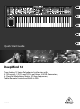
DeepMind 12 Controls
(EN) Step 2: Controls
(5) (6) (7) (1) (3)
(20)
(19)
(18)
(17)
(16)
(15)
(14)
(1) DISPLAY - this large backlit LCD screen
shows the synthesizer status, parameters,
and the ve main menus. The contrast and
brightness are adjustable on the SYSTEM
SETTINGS page of the GLOBAL menu.
(2) NAVIGATION - navigate within the display
menus using the UP, DOWN, +/YES and
-/NO buttons.
(3) MENUS - these switches allow access to the
display menus.
PROG MENU- the main display of the
synthesizer. Shows the current program, the
currently adjusted parameter and a visual
representation of the parameter and the
three envelopes.
FX MENU - add up to four e ects from the
list available. Change the e ects routing by
selecting one of the ten MODEs available.
Each of the e ects has individual controls
for all parameters.
GLOBAL MENU - view and adjust settings
for the synthesizer. There are ve pages,
CONNECTIVITY, KEYBOARD, PEDAL,
FADER and SYSTEM.
COMPARE MENU - in this menu, you can
compare the current program with the stored
program and see the di erence in physical
fader positions.
WRITE MENU - in this menu, you can write
the current program settings to the program
library. You can also rename the program and
set its category type.
(4) DATA ENTRY - selected parameters on the
display are adjusted using the rotary knob or
the fader. The rotary knob has a click which
allows very accurate control. The fader allows
rapid adjustment across the full range.
MOD- this switch opens the modulation
matrix on the display and allows up to 8
modulations to be created from the list of
sources and destinations.
(5) ARP/SEQ - this area controls the arpeggiator
and the control sequencer.
ON/OFF - when activated, this generates an
arpeggio based on pressed keys. Note - the
control sequencer is turned on from its edit
page only.
RATE - adjusts the rate of the arpeggiator /
sequencer in beats per minute (BPM).
GATE TIME - adjusts the duration of the note
played based on a percentage of the time
between triggered notes.
CHORD - allows you to play any chord with a
single key. The chord is given a root note and
mapped across the keyboard.
POLY CHORD - allows you to play multiple
chords from multiple keys. The chords are
mapped to individual keys.
TAP/HOLD - tap this button in time with
your performance to set the rate/BPM, or
press and hold to engage the HOLD function.
EDIT - this allows additional arpeggiator/
control sequencer parameters to be edited
from the main display.
(6) LFO 1 and 2- low frequency oscillators used
to modulate or control other parameters.
RATE- this sets the rate, or speed of the LFO.
DELAY TIME - the duration of time which
will elapse before the LFO starts.
EDIT - this allows additional LFO parameters
to be edited from the main display.
LFO WAVEFORMs - these LEDs indicate the
type and status of the waveforms produced
by each LFO.
(7) DCO 1 & 2 - These analog full range
oscillators create waveforms which are the
sound source of the synthesizer.
DCO 1 & 2 PITCH MOD - amount of pitch
modulation applied to respective DCO.
DCO 1 SQUAREWAVE- this switch turns the
square wave output for DCO 1 on/o .
DCO 1 PWM - amount of pulse
width modulation applied to
the DCO 1 square wave.
DCO 1 SAWTOOTH- this switch turns the
sawtooth output for DCO 1 on/o .
DCO 2 TONE MOD- amount of tone
modulation applied to DCO 2.
DCO 2 PITCH- controls the base pitch
of DCO 2.
DCO 2 LEVEL- controls the level of DCO 2.
NOISE LEVEL- controls the amount of white
noise added to the oscillators.
EDIT- this allows additional DCO parameters
to be edited from the main display.
(8) POLY - this area is used to control the
polyphony of the synthesizer.
UNISON DETUNE - when voices are playing
in unison, this adjusts the amount of
detuning between the voices.
EDIT- this allows additional POLY parameters
to be edited from the main display.
(9) VCF - the voltage controlled low pass lter
used to lter high frequencies from the
sound of the synthesizer.
FREQ - adjusts the cut-o frequency of
the lter.
2-POLE - changes the roll o slope of the
lter from the default 4-POLE mode to a
2-POLE mode.
RES - adjusts the resonance of the lter
cut-o point.
EDIT - allows additional VCF parameters to
be edited from the main display.
ENV - adjusts the level of the VCF ENVELOPE
which controls the lter cut-o frequency.
INVERT - used to invert the polarity of
the VCF envelope applied to the lter
cut-o frequency.
LFO - adjusts the depth of the selected
LFO waveform applied to the lter
cut-o frequency.
KYBD - adjusts the amount of keyboard
tracking to be applied to the lter
cut-o frequency.
(10) VCA - the voltage controlled ampli er used
to control the output level.
LEVEL - controls the output level of the VCA.
EDIT - this allows additional VCA parameters
to be edited from the main display.
(11) HPF - the voltage controlled high pass lter
used to lter low frequencies from the sound
of the synthesizer.
FREQ - used to adjust the frequency of the
high pass lter.
BOOST - this switch applies a +12 dB bass
boost to the signal path
(2) (4) (8) (9) (10) (11) (12)
(13)
(20)