
Owners Manual


3
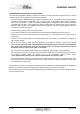
1 VOLUME control
Issue 2
Page 7 of 13
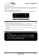
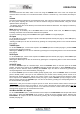
XLR Balanced input and output lead
connections:
(for reference, no XLR signal leads supplied)
Pin functions:
1 Ground (cable shield)
2 Normal polarity ("hot" or “+”)
3 Inverted polarity ("cold" or “-“)
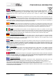
FACILITIES & CONNECTIONS
2 VOLUME display (in decibels)
3 ON/OFF Button
4 CD, TUNER, AUX1, AUX2/HT, BALANCED 1,
BALANCED 2 input selector.
5 IR RECEIVER lens
7 USB input
8 CD, TUNER, AUX/HT RCA left and right inputs
9 XLR BALANCED 1 & 2 right and left inputs
10 RCA main outputs left and right
11 XLR BALANCED PRE outputs left and right
12 TRIGGER IN/OUT 3.5mm mono jack sockets
124
5
12
8
9
10
11
14
7 15
13 16
6 POWER LED
6
1
3
HT/AUX Selector for HT/AUX inputs
14 IEC MAINS INPUT
15 OPTICAL&COAX
digital input 1&2
16
OPTICAL&COAX
digital output