
Specifications


A1 FBP
FACILITIES AND CONNECTION
Issue 1: 20
th
May 2008
Page 7 of 15
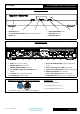
FBP FRONT PANEL
1 2 3 4 5 6
1. ON/OFF Button
2. ANALOGUE, USB INPUT source selector buttons
3. DISPLAY
4. TAPE MONITOR button
5. VOLUME up/down
6. IR RECIEVER lens
FBP REAR PANEL
7 8 9 10 11 12 13 14 15 16 17 18
7. USB Input (type ‘B’ socket)
8. PHONO INPUT RCA Sockets
9. PHONO GROUNDING 4mm post
10. CD, TUNER, AUX/HT, TAPE INPUT RCA
Sockets
11. AUX/HT input configuration switch
12. TAPE OUTPUT RCA sockets
13. BALANCED/HT INPUT 1 input configuration
switch
14. BALANCED INPUTS 1/HT left and right
15. XLR BALANCED INPUTS 2 XLR left and right
16. PREAMP OUTPUT RCA sockets
17. BALANCED OUPUTS XLR left and right
18. POWER INPUT XLR from Power Supply Unit
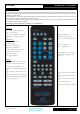
XLR Balanced input and output lead connections:
(for reference only, no XLR signal leads supplied)
Pin functions:
1 Ground (cable shield)
2 Normal polarity ("hot" or “+”)
3 Inverted polarity ("cold" or “-“)