PaxFreehandBW/Lg-2.eps—10/04/04 Owner’s Installation Guide for the Paxton Automotive Novi Supercharger for the 2005-2010 Mustang GT* *Legal in California only for racing vehicles which may never be used upon a highway 2007-2010 models Paxton Automotive . 1300 Beacon Place . Oxnard CA 93033 805 487-3796 • FAX 805 247-0669 i P/N: 4809654 v5.0 ©2010 Paxton Automotive All Rights Reserved, Intl. Copr.
FOREWORD T his manual provides information on the installation, maintenance and service of the Paxton supercharger kit expressly designed for this vehicle. All information, illustrations and specifications contained herein are based on the latest product information available at the time of this publication. Changes to the manual may be made at any time without notice.
TABLE OF CONTENTS FORWORD ii TABLE OF CONTENTS . . . . . . . . . . . . . . . . . . . . . . . . . . . . . . . . . . . . . . . . . . . . . . . . . . . . . . . . . . . . . . . . . . . . . . . . . . . . . . . . . . . . . iii IMPORTANT NOTES . . . . . . . . . . . . . . . . . . . . . . . . . . . . . . . . . . . . . . . . . . . . . . . . . . . . . . . . . . . . . . . . . . . . . . . . . . . . . . . . . . . . . . . iv RECOMMENDED TOOLS FOR INSTALLATION . . . . . . . . . . . . . . . . . . . . . . . . . . . . . . .
2005-2010 Mustang GT IMPORTANT NOTES T his product is protected by state common law, copyright and/or patent. All legal rights therein are reserved. The design, layout, dimensions, geometry and engineering features shown in this product are the exclusive property of Paxton Automotive.
B 2005-2010 Ford Mustang GT efore beginning this installation, please read through this entire instruction booklet and the Street Supercharger System Owner's Manual which includes the Automotive Limited Warranties Program and the Warranty Registration form. Paxton supercharger systems are performance improving devices. In most cases, increases in torque of 30-35% and horsepower of 35-45% can be expected with the boost levels specified by Paxton Automotive.
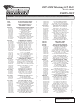
2005-2006 Mustang GT, H.O. Part No. 1001850 cont’d PARTS LIST IMPORTANT: PaxFreehandBW/Lg-2.eps—10/04/04 Before beginning installation, verify that all parts are included in the kit. Report any shortages or damaged parts immediately. Part No. Description 1016137 S/C ASY, NOVI 2200 '05 MUST SAT, 3.
2005-2006 Mustang GT, H.O. Part No. 1001850 cont’d PARTS LIST IMPORTANT: PaxFreehandBW/Lg-2.eps—10/04/04 Part No. 8F101-262 7U032-016 7U100-055 7R004-002 8F001-255 7R002-044 7R004-006 5W001-022 5W001-009 5W001-080 7P375-099 7U032-025 7U032-030 Before beginning installation, verify that all parts are included in the kit. Report any shortages or damaged parts immediately. Description FUEL PMP ASY, '05 MUST TWIN INTA 3/8" EFI FUEL HSE HI-PSR TIE-WRAP, 7.
2005-2006 Mustang GT, Standard Part No. 1001851 PARTS LIST IMPORTANT: PaxFreehandBW/Lg-2.eps—10/04/04 Before beginning installation, verify that all parts are included in the kit. Report any shortages or damaged parts immediately. Part No. Description Qty. 1016130 SUPERCHARGER ASY, 3.
2007-2008 Mustang GT, H.O. Part No. 1001852 PARTS LIST IMPORTANT: PaxFreehandBW/Lg-2.eps—10/04/04 Part No.
2007-2008 Mustang GT, H.O. Part No. 1001852, cont'd PARTS LIST IMPORTANT: PaxFreehandBW/Lg-2.eps—10/04/04 Before beginning installation, verify that all parts are included in the kit. Report any shortages or damaged parts immediately. Part No.
2007-2008 Mustang GT, Standard Part No. 1001853 PARTS LIST IMPORTANT: PaxFreehandBW/Lg-2.eps—10/04/04 Part No.
2005-2006 Mustang GT, H.O. Part No. 1001850SL PARTS LIST IMPORTANT: PaxFreehandBW/Lg-2.eps—10/04/04 Before beginning installation, verify that all parts are included in the kit. Report any shortages or damaged parts immediately. Part No.
2005-2006 Mustang GT, H.O. Part No. 1001850SL, cont'd PARTS LIST IMPORTANT: Before beginning installation, verify that all parts are included in the kit. Report any shortages or damaged parts immediately. PaxFreehandBW/Lg-2.eps—10/04/04 Part No. 8F101-262 7U032-016 7U100-055 7R004-002 8F001-255 7R002-044 7R004-006 5W001-022 5W001-009 5W001-080 7P375-099 7U032-025 7U032-030 Description FUEL PMP ASY, '05 MUST TWIN INTA 3/8" EFI FUEL HSE HI-PSR TIE-WRAP, 7.
2005-2006 Mustang GT, Standard, SL Part No. 1001851SL PARTS LIST IMPORTANT: PaxFreehandBW/Lg-2.eps—10/04/04 Before beginning installation, verify that all parts are included in the kit. Report any shortages or damaged parts immediately. Part No.
2007-2008 Mustang GT, H.O., SL Part No. 1001852SL PARTS LIST IMPORTANT: PaxFreehandBW/Lg-2.eps—10/04/04 Before beginning installation, verify that all parts are included in the kit. Report any shortages or damaged parts immediately. Part No.
2007-2008 Mustang GT, H.O., SL Part No. 1001852SL cont’d PARTS LIST IMPORTANT: PaxFreehandBW/Lg-2.eps—10/04/04 Before beginning installation, verify that all parts are included in the kit. Report any shortages or damaged parts immediately. Part No.
2007-2008 Mustang GT, Standard, SL Part No. 1001853SL PARTS LIST IMPORTANT: PaxFreehandBW/Lg-2.eps—10/04/04 Part No.
2010 Mustang GT, H.O. Part No. 1001862SL PARTS LIST IMPORTANT: Before beginning installation, verify that all parts are included in the kit. Report any shortages or damaged parts immediately. PaxFreehandBW/Lg-2.eps—10/04/04 Part No. Description Qty.
2010 Mustang GT, H.O. Part No. 1001862SL, cont'd PARTS LIST IMPORTANT: PaxFreehandBW/Lg-2.eps—10/04/04 Part No. 7J3112-000 7R002-044 7A312-050 8PN010-030 7R002-016 7P1156-082 7U030-046 8D001-001 7U034-016 7P750-100 7P218-156 7U100-055 7R002-040 7U133-045 7PS300-275 7PS300-045 Before beginning installation, verify that all parts are included in the kit. Report any shortages or damaged parts immediately.
This Page Left Intentionally Blank P/N: 4809654 v5.0 ©2010 Paxton Automotive All Rights Reserved, Intl. Copr.
1. PREPARATION/REMOVAL MAF CONNECTOR A. Loosen the hose clamp at the throttle body. Disconnect the plastic 3/8" tube assembly attached to the passenger’s side valve cover. Remove the plastic 3/8" x 90° connector from the plastic tube that was connected at the passenger’s side valve cover. Set this connector aside to be re-used in a later step. Discard the remainder of the hose assembly, as it will not be re-used. (See Fig. 1-a.) RETAIN THIS END RETAIN THIS END Fig. 1-c C.
1. PREPARATION/REMOVAL, cont’d J. E. Locate the coolant drain plug on the passenger side of the radiator. Next drain the coolant into a clean container. This coolant will be reused in a later step. F. Remove the two 8mm headed bolts securing the coolant overflow reservoir to the plastic fan shroud. (See Fig. 1-f.) G. Disconnect the small overflow hose (running across the top of the radiator) from the overflow reservoir. (See Fig. 1-f.
1. PREPARATION/REMOVAL, cont’d 4. 5. vacuum line from the fuel regulator. Remove the rails and injectors as a complete unit and set aside. New injectors will be installed in a later step. (See Figs. 1-i, 1-j.) Locate and remove the remaining 10mm headed bolts retaining the intake manifold to the cylinder heads. There are five on each side. (2005-2006 Only): Remove the intake manifold and set aside so it can be reinstalled after modifications to the coolant crossover tube are made.
1. PREPARATION/REMOVAL, cont’d Q. Locate and remove the stud that secures the alternator in place as well as the stud-bolts located to the right of the alternator. (See Fig. 1-k.) MODIFY STUD STUD BOLT REMOVE 13mm HEADED BOLT TAB REMOVED Fig. 1-m REMOVE STUD BOLT MODIFIED STUD BOLT Fig. 1-k R. There is a small tab that secures the wiring harness in place on the valve cover that will need to be removed to gain clearance for the supercharger belt.
2. OIL FEED INSTALLATION (Engine oil-fed kits only. Applications with “SL” kits ignore Sections 2 & 3 and skip ahead to Step 4.) A. Locate the factory oil sensor on the driver’s side of the vehicle near the oil filter. B. Remove the sending unit and set aside. C. Locate the supplied 1/4"NPT street TEE fitting. Install the TEE in the same location as the factory sending unit with the 1/4" x –4 x 90° installed in the TEE at the location noted. (See Fig. 2-a.) D.
This Page Left Intentionally Blank P/N: 4809654 v5.0 ©2010 Paxton Automotive All Rights Reserved, Intl. Copr.
3. OIL DRAIN ASSEMBLY INSTALLATION F. Thoroughly clean the threaded area. Apply a small amount of silicone sealer or teflon paste to the new threads. Apply more sealer to the 3/8"NPT hose fitting and secure in the hole. Make sure a seal is formed all around the fitting. (See Fig. 3-b.) G. Drain the engine oil and change the filter. (Engine oil-fed kits only. Applications with “SL” kits ignore this step and skip ahead to Step 4.) A.
This Page Left Intentionally Blank P/N: 4809654 v5.0 ©2010 Paxton Automotive All Rights Reserved, Intl. Copr.
4.1 POWER STEERING RELOCATION (20052009 mODEL S oNLY) D. Attach the 3/4" and the 3/8" hose barb unions to the factory hoses using the factory clamps. E. Attach the reservoir to the passenger’s side radiator core support using one of the factory ground strap retaining bolts. (See Fig. 4.1-c.) A. Locate the power steering assembly 4FU110010. B. Attach the P/S relocation bracket 4FU010-010 using the hardware provided to the P/S reservoir removed in an earlier section. (See Fig. 4.1-a.) Fig. 4.1-c F.
4.2 POWER STEERING RELOCATION (2010 Models Only) D. Using a 3/4" brass union and two stepless clamps, attach the 90° bend to a length of supplies 3/4" hose as shown. Do the same to the 3/8" hose. (See Fig 4.2-c) A. Locate the power steering assembly 4FU110101. B. Attach the P/S relocation bracket 4FU010-101 using the hardware provided to the P/S reservoir removed in an earlier section. (See Fig. 4.2-a.) Fig. 4.2-c E. Attach the 90° 3/4" and 3/8" you trimmed off to reservoir using the factory clamps.
5.1 COOLANT TUBE RELOCATION (20052006 Only) A. Locate assembly 4FU214-021. B. Remove the hose connected to the back lower portion of the engine coolant cross-over tube. (See Fig. 5.1-a.) HOSE CONNECTION BLEED PLUG Fig. 5.1-c E. F. Fig. 5.1-a C. Remove the nylon clip retaining the wire harness to the alternator brace and the four 10mm headed bolts securing the alternator brace. Set the brace aside to be reinstalled. (See Fig. 5.1b.
5.1 COOLANT TUBE RELOCATION, (20052006 Only) cont’d G. Locate the supplied 1-1/4" expansion plug (7P125-002.) H. Coat the expansion plug with sealant. Using a tube or socket that matches the recessed diameter of the plug, install the plug flush with the machined surface sealing the outlet of the crossover tube. (See Figs. 5.1-e, 5.1-f.) Fig. 5.1-g J. Install the fitting in the location of the factory coolant bleed plug. (See Fig. 5.1-h.) Screw the jam nut all the way onto the fitting.
5.1 COOLANT TUBE RELOCATION, (2005-2006 Only) cont’d *** NOTE *** The preferred method of removing the hose-end is to apply a small amount of heat to the plastic tube and slide the ends free. N. Tighten the cross-over tube retaining bolts, and remove the two manifold retaining bolts. O. Reconnect the coolant cross-over tube hose at the lower rear portion of the coolant cross-over tube. Remove any coolant that may have spilled into the engine valley. P.
5.2 A. B. C. D. E. F. G. H. I. J. THERMOSTAT HOUSING/RADIATOR HOSE MODIFICATION (2007-2010 Model Year Only) Using an 8mm socket, remove the two 6mm screws that retain the thermostat housing. Set the housing aside to be reused later. Leave the factory thermostat and O-ring seal in place as they will be reused (provided they are in good condition). (See Fig. 5.2-a.) Locate the supplied thermostat housing adaptor and hardware. Using the two 6mm sockethead screws, install the housing adaptor as shown.
5.2 K. L. M. N. O. THERMOSTAT HOUSING/RADIATOR HOSE MODIFICATION (2007-2010 Model Year Only), cont’d CUT APPROX. 2.25" AND SET ASIDE Locate the 4FU114-030 water pipe assembly. Cut approximately 2.25" off the short 90° end of the factory radiator hose and set aside. (See Fig. 5.2-l.) Cut the remainder of the short 90° bend from the factory radiator hose, approximately half way between the 90° bend and the 45° bend, and discard. (See Fig. 5.2-l.) Using the 2.
This Page Left Intentionally Blank P/N: 4809654 v5.0 ©2010 Paxton Automotive All Rights Reserved, Intl. Copr.
6. SUPERCHARGER MOUNTING PLATE INSTALLATION C. It is necessary to install the supercharger accessory drive belt and loosely route it following Fig. 6-e, as not all pulleys are currently in place. D. Locate the supercharger mounging plate 4FU010-044 from the supercharger mounting plate assembly. (See Fig. 6-c.) E. Locate the two 8mm x 140mm long bolts and washers from the mounting bracket assembly and install in the locations noted. (See Fig. 6-c.) A.
P/N: 4809654 v5.0 ©2010 Paxton Automotive All Rights Reserved, Intl. Copr. Secured 18 A/C COMPRESSOR PULLEY FACTORY TENSIONER PULLEY FACTORY IDLER PULLEYS ALTERNATOR PULLEY Fig. 6-e / Belt routing FACTORY POWER STEERING PULLEY SUPERCHARGER PULLEY CRANK SHAFT PULLEY SUPPLIED IDLER PULLEY 4PCS016-160 6.
6. SUPERCHARGER MOUNTING PLATE INSTALLATION, cont’d I. J. L. Locate the 8mm x 150mm bolt and washer. Loosely install the bolt through the mounting plate and remaining 2.712" long spacer into the engine cover using Fig. 6-a for location reference. Locate the supplied idler, 1.776" idler spacer, idler pilot spacer, 3/8-16 x 3.75" long bolt and washer. Install the bolt/washer through the mounting plate, 1.776" spacer, supplied idler, idler pilot spacer and into the triangle-shaped bracket. Use Figs.
This Page Left Intentionally Blank P/N: 4809654 v5.0 ©2010 Paxton Automotive All Rights Reserved, Intl. Copr.
7. THERMOSTAT HOUSING RELOCATION *** NOTE *** Because of manufacturing tolerances, it is best to leave this hose long and trim to fit. A. It will be necessary to relocate the thermostat housing to gain clearance for the supercharger mounting bracket. B. Locate hose 7U133-050. The hose will be modified and will replace the factory lower radiator hose removed in a previous step. (See Fig. 7-a.) E. F. Install the long end of the modified hose to the outlet of the radiator with a #24 hose clamp.
7. THERMOSTAT HOUSING RELOCATION, (2005-2006 Only) cont’d *** NOTE *** The hose clamps will be left loose for adjustment of the thermostat’s location until after the installation of the supercharger and supercharger mounting bracket are installed. G. H. I. Locate the 7U133-190 molded coolant hose. (See Fig. 7-c.) Install the end with the 90° bend onto the thermostat housing. Install the opposite end to the previouusly modified coolant cross-over tube. Secure using the #20 hose clamps provided. (See Fig.
4. *** NOTE *** For non-cooled kits skip this section and proceed to Section 9. Remove the five plastic clips retaining the front portion of the fender liner. Both sides need to be removed. (See Fig. 8A-c.) 8A. BUMPER COVER AND SPLASH PAN (H.O. Kits Only) 1. Raise the vehicle with a floor jack and set on jack stands. 2. Remove the seven 5.5mm headed screws retaining the lower splash panel. (See Fig. 8A-a.) Section 1 PREPARATION/REMOVAL Fig. 8A-c 5.
8A. BUMPER COVER & SPLASH PAN REMOVAL (H.O. Kits Only), cont’d 6. Disconnect the connectors on the parking and the lower fog lights. (See Fig. 8A-e.) 10mm HEADED BOLT Fig. 8A-g LIGHT CONNECTIONS 9. Lift up on the tabs releasing them from the clips. (See Fig. 8A-h.) Fig. 8A-e 7. Remove the six nylon clips retaining the upper radiator core support cover. (See Fig. 8A-f.) NYLON CLIPS DRIVING LIGHT CONNECTOR Fig. 8A-h 10. Pull out on the bumper cover 11.
8A. BUMPER COVER & SPLASH PAN REMOVAL (H.O. Kits Only), cont’d 13mm HEADED BOLTS Fig. 8A-k 16. Fig. 8A-i 14. 17. Remove four nylon push pins from the styrofoam bumper support and set the support and the pins aside to be reinstalled. (See Fig. 8A-j.) Replace the bolts previously removed with the four 8mm-1.25" x 35mm long bolts and washers provided. Install the four 2A017-036 spacers (two each side) to the bolts. (See Fig. 8A-l). SPACERS PROVIDED NYLON PUSH PINS AIR DIVERSION PANELS Fig. 8A-l 18.
8B. CHARGE AIR COOLER CORE INSTALLATION (2005-2006 Model H.O. Kits Only) SHORT ENDS OF 90° ELBOWS PROVIDED *** NOTE *** Use Fig. 8B-a to aid in the next few steps DISCHARGE DUCT CHARGE COOLER TUBE “C” TUBE “D” Fig. 8B-c TUBE “B” 3. TUBE “A” *** NOTE *** The by-pass port should be facing the driver’s side TUBE “E” 4. Fig. 8B-a 1. Using a 3" x 3" bump sleeve and two #48 hose clamps, loosely attach tube “A” to the supercharger discharge. Locate the Charge Air Cooler assembly.
8B. CHARGE AIR COOLER CORE INSTALLATION (2005-2006 H.O. Kits Only), cont’d 5. 6. Install the provided 3" x 3" sleeve and #48 hose clamps onto the open end of tube “B”. Using a 5/16-18 tap, tap the lower hole on the driver’s and passenger’s side core support. Locate the tube support brackets, 5/16-18 x 1/2" screws and washers. Loosely attach the tube support brackets to the core support. (See Fig. 8B-e, 8B-g.) 9. Attach a 3" x 3" sleeve and #48 hose clamps to the open end of tube “D”. 10.
8C. COMPRESSOR BYPASS VALVE #1 ASSEMBLY INSTALLATION: (2005-2006 H.O. Kits Only) 1. Cut a piece of the provided 1" heater hose approximately 3" long and secure it to the bypass valve inlet (opposite the vacuum port) using the #16 hose clamps provided. 2. Locate the 1" molded rubber 90° elbow and cut approximately 6" from the long end and 1" from the short end. Attach the long end to the by-pass valve discharge and secure using the #16 hose clamps provided. (See Fig. 8C-a, 8D-c.) 3.
3. 8D. COMPRESSOR BYPASS VALVE #2 ASSEMBLY INSTALLATION (2005-2006 Model H.O. Kits Only) 1. Cut a piece of the supplied 1" heater hose 4.5" long and a piece 15" long. 2. Attach the 4.5" piece of hose to the inlet of the by-pass valve, securing it with a #16 hose clamp. 4. Secure the 15" piece to the by-pass valve discharge using a #16 hose clamp. Attach the open end of the 4.5" hose to the by-pass port on the cast discharge duct and secure using a #16 hose clamp.
8D. COMPRESSOR BYPASS VALVE #2 ASSEMBLY INSTALLATION (2005-2006 H.O. Kits Only), cont’d 5. 6. 7. 8. Attach a length of 5/32" vacuum hose to bypass valve #2 and route to the vacuum port of the fuel rail sensor. Cut a section of the factory hose and install the vacuum TEE that is provided. (See Fig. 8D-b.) Attach the vacuum hose from the bypass valve to the TEE. Attach a length of 5/32" vacuum hose to the previously installed bypass valve #1.
BYPASS VALVE 4.5" LENGTH OF HOSE #16 HOSE CLAMPS ON ALL HOSE ENDS PORT ON THROTTLE BODY DUCT TUBE “A” VACUUM TEE AT FUEL REGULATOR 31 OF HOSE P/N: 4809654 v5.0 ©2010 Paxton Automotive All Rights Reserved, Intl. Copr. Secured Fig. 8D-c TO 90° RUBBER HOSE 3" LENGTH OF HOSE 15” LENGTH VACUUM TEE APPROX. 5.75" BYPASS VALVE 7U133-100 MOLDED 90° HOSE VIEW FROM FRONT OF VEHICLE APPROX. 4" TO STRAIGHT FITTING ON INLET DUCT 8D. COMPRESSOR BYPASS VALVE #2 ASSEMBLY INSTALLATION (2005-2006 H.O.
8E. HORN BRACKET & RELOCATION (2010 Model H.O. Kits Only) 1. Remove factory horn bracket assembly from vehicle with 8mm socket. Loosen horns with 10mm socket and rotate 180° as shown. Fig. 8E-c Installed view of bracket on vehicle Fig. 8E-a 2. Reinstall horn bracket upside down on car and reattach plug. The horns should face down and the bracket should be facing up, opposite of the OEM installation.. 180° FLIP Fig. 8E-b P/N: 4809654 v5.0 ©2010 Paxton Automotive All Rights Reserved, Intl. Copr.
8F. AIR DIVERSION PANEL MODIFICATION (2010) Models Only) 1. You will need to trim the air diversion panels previously removed in step 8A, Fig 8A-j. On the drivers side, measure from the top 12" and cut the remaining material below. (See Fig 8F-a) Fig. 8F-c 12" Fig. 8F-a 2. On the passenger side, measure from the top 15 1/2" and cut the remaining material below. (See Fig 8F-b) Fig. 8F-d 4. Reinstall the air diversion panels back onto the car.
8G. CHARGE AIR COOLER CORE INSTALLATION (2007-2010 Model H.O. Kits Only) SHORT ENDS OF 90° ELBOWS PROVIDED *** NOTE *** Use Fig. 8G-a to aid in the next few steps DISCHARGE DUCT TUBE “C” TUBE “D” Fig. 8G-c TUBE “A” *** NOTE *** For better duct clearance, rotate the power steering return fitting so that it points to the front of the vehicle. Use care not to damage the fitting or hose. If necessary, rotate the power steering line from the rack to the radiator closer to the frame. (See Fig. 8G-d.
8g. CHARGE AIR COOLER CORE INSTALLATION (2007-2010 Model H.O. Kits Only), cont’d 3. 4. 8. Install the provided 3" x 45° sleeve and #48 hose clamps onto the open end of tube “A”. Using a 5/16-18 tap, tap the lower hole on the driver’s and passenger’s side core support. Locate the tube support brackets, 5/16-18 x 1/2" screws and washers. Loosely attach the tube support brackets to the core support. (See Fig. 8G-f, 8G-i) UPPER HOLE 7.
8H. COMPRESSOR BYPASS VALVE #1 INSTALLATION (2007-2010 Model H.O. Kits Only) 1. 2. 3. Cut a piece of the provided 1" heater hose approximately 4.25" long and secure it to the by-pass valve inlet (opposite the vacuum port) using the #16 hose clamps provided. Locate the 1" molded rubber 45° elbow and cut approximately 6" from the long end and 1" from the short end. Attach the long end to the by-pass valve discharge and secure using the #16 hose clamps provided. (See Fig. 8H-a, 8I-a.
8I. COMPRESSOR BYPASS VALVE #2 INSTALLATION (2007-2010 Model H.O. Kits 3. Only) 1. 2. 4. Cut a piece of the supplied 1" heater hose 9.5" long and a piece 14.5" long. Attach the 9.5" piece of hose to the inlet of the by-pass valve, securing it with a #16 hose clamp. Secure the 14.5" piece to the by-pass valve discharge using a #16 hose clamp. Attach the open end of the 9.5" hose to the by-pass port on the cast discharge duct and secure using a #16 hose clamp. The open end of the 14.
8I. COMPRESSOR BYPASS VALVE #2 INSTALLATION (2007-2010 Model H.O. Kits Only), cont’d 5. 6. 7. 8. Attach a length of 5/32" vacuum hose to bypass valve #2 and route to the vacuum port of the fuel rail sensor. Cut a section of the factory hose and install the vacuum TEE that is provided. (See Fig. 8I-b.) Attach the vacuum hose from the bypass valve to the TEE. Attach a length of 5/32" vacuum hose to the previously installed bypass valve #1.
BY-PASS VALVE #16 CLAMPS ON ALL HOSE ENDS PORT ON THROTTLE BODY DUCT 39 P/N: 4809654 v5.0 ©2010 Paxton Automotive All Rights Reserved, Intl. Copr. Secured Fig. 8I-c BYPASS VALVE MOLDED 45°HOSE (7U133-045) APPROX. 4.50° VIEW FROM FRONT OF VEHICLE VACUUM TEE TO 45° RUBBER HOSE 4.25" LENGTH OF HOSE VACUUM TEE AT FUEL REGULATOR 8I. COMPRESSOR BYPASS VALVE #2 INSTALLATION (2007-2010 Model H.O.
3. 8J. WIRING HARNESS RELOCATION (H.O. Kits Only) 1. On the passenger’s side of the engine, attached to the valve cover, is a large wire harness. The harness will have to be relocated to gain clearance for the radiator overflow reservoir. (See Fig. 8J-a.) 4. 5. 6. Remove the small clip retaining the small wiring harness to the shock tower. (See Fig. 8J-b.) Attach the small harness to the large harness with wire ties.
*** NOTE *** 2007-2010 Models skip to 8L 8K. ENGINE COOLANT RESERVOIR BRACKET INSTALLATION (2005-2006 Model H.O. Kits Only) 1. Locate assembly 8N155-080. 2. Attach the rear reservoir mounting bracket 4FU010-051 to the reservoir with the 1/420 x 3/4" long bolts and washers provided. (See Fig. 8K-a.) Fig. 8K-b 4. Locate and install 1/4"NPT x 3/8" barbed fitting in the tapped hole just above the previously installed mounting bracket. This hole may have to be opened using the appropriate drill bit.
8K. ENGINE COOLANT RESERVOIR 7. INSTALLATION (2005-2006 Model H.O. Kits Only), cont’d 5. Remove the 10mm headed bolt that secures the back of the ECU and the power distribution box. (See Fig. 8K-d.) Attach the rear mounting bracket to the strut tower with the 6mm x 20mm long screws and washer provided. (See Fig. 8K-f.) *** NOTE *** Reinstall the factory ground wire with one of the 6mm screws and washers. FACTORY GROUND STRAP 10mm HEADED BOLT Fig. 8K-f Fig. 8K-d 6. 8.
8K. ENGINE COOLANT RESERVOIR 12. Route the overflow hose across the radiator and under the radiator retaining bracket to the 1/4"NPT x 3/8" hose barb fitting in the coolant reservoir securing with a clamp. (See Fig. 8K-j.) INSTALLATION (2005-2006 Model H.O. Kits Only), cont’d 9. Reinstall the factory passenger’s side upper radiator hose removed in a previous step. (See Fig. 8K-j.) 10. Modify the small hose removed from the factory coolant overflow reservoir. By cutting the “S” bend off the hose end.
8L. ENGINE COOLANT RESERVOIR INSTALLATION (2007-2010 Model H.O. Kits Only) 1. Locate assembly 8N155-082. 2. Attach the rear reservoir mounting bracket 4FU010-091 to the reservoir with the 1/420 x 1/2" long bolts and washers provided. (See Fig. 8L-a.) 3. Attach bracket 4FU010-061 to the front of the reservoir with the hardware provided. (See Fig. 8L-b.) 4. Locate and install 1/4"NPT x 3/8" barbed fitting in the tapped hole just above the previously installed mounting bracket.
8L. ENGINE COOLANT RESERVOIR INSTALLATION (2007-2010 Model H.O. Kits Only), cont’d 5. 6. Remove the 10mm headed bolt that secures the back of the ECU and the power distribution box. (See Fig. 8L-d.) Install the coolant reservoir. Secure the front of the reservoir with the factory fastener removed previously. (See Fig. 8L-e.) 10mm HEADED BOLT ***NOTE*** Leave this bolt loose for final adjustment in a later step. 7. 8. Fig.
8L. ENGINE COOLANT RESERVOIR INSTALLATION (2007-2010 Model H.O. Kits Only), cont’d 9. 10. 11. Modify the small hose removed from the factory coolant overflow reservoir. By cutting the "S” bend off the hose end. (See Fig. 8L-h.) Install a 3/8" union and a #17 stepless clamp. Secure the clamp. Using a length of 3/8" (approximately 40" long) hose that is provided, secure the hose to the union with a #17 stepless clamp. (See Fig. 8L-i.
8M. BUMPER COVER AND SPLASH PAN MODIFICATION (2010 Model H.O. Kits Only), cont'd 2. In the corners of the bumper cover opening you will have approximately 3/4" of material remaining on both sides. Draw a line from here meeting your corner cuts and trim the remainder off. This should leave approximately 3" of bumper cover material in the center. These modifications can be made using a die grinder with a cut-off wheel or other suitable tool. Use a straight edge to keep your cuts true and even. (See Fig 8M-b).
9. AIR DISCHARGE ASSEMBLY (Non-Cooled H. Connect the supplied length of 5/32" vacuum to the port on the bypass valve. Route the line to the fuel regulator vacuum hose. Using the supplied vacuum TEE, connect the bypass vacuum line. (See Figs. 9-b, 9-c on Page 9-2, for assistance.) Kits Only) A. Attach the 4.5" sleeve to the discharge duct with the #72 clamps provided. B. Install the 3.0" x 2.75" reducer to the inlet of the discharge duct. C.
9. AIR DISCHARGE ASSEMBLY (Non-cooled Kits Only) 4.25" x Ø1" HOSE (TRIM TO FIT) TO DISCHARGE TUBE BYPASS VALVE 15" x Ø1" HOSE (TRIM TO FIT) TO INLET DUCT #16 HOSE CLAMPS TO MANIFOLD PRESSURE/VACUUM Fig. 9-b FUEL REGULATOR SUPPLIED VACUUM TEE Fig. 9-c 49 P/N: 4809654 v5.0 ©2010 Paxton Automotive All Rights Reserved, Intl. Copr.
10. COOLANT RESERVOIR RE-INSTALLATION (Non-cooled Kits Only) A. Reinstall the factory passenger’s side upper radiator hose removed in a previous step. B. Reinstall the factory coolant reservoir using factory hardware to secure. C. Reattach the large hose at the bottom of the reservoir to the thermostat housing using the factory hose clamp. D. Reconnect the small overflow hose at the top using the factory clamps. E.
This Page Left Intentionally Blank 51 P/N: 4809654 v5.0 ©2010 Paxton Automotive All Rights Reserved, Intl. Copr.
11. CRANK CASE BREATHER AND PCV INSTALLATION PCV VAVLE A. Locate the pre-assembled PVC/MAF assembly 4FU139-096. B. Locate the factory 5/8" x 90° hose end connector and the factory striaght hose connection removed in a previous step. Connect the hose closest to the PCV valve to the 90° fitting as shown in picture using stepless clamps provided. Connect the straight connector to the remaining hose using the stepless clamps provided. C.
This Page Left Intentionally Blank 53 P/N: 4809654 v5.0 ©2010 Paxton Automotive All Rights Reserved, Intl. Copr.
12. AIR INLET ASSEMBLY A. Locate assembly 4FU112-010. B. Remove two of the 3/8-16 x 1" bolts securing the supercharger in place. Install the air inlet support bracket and secure with the 3/8" bolts removed from the supercharger mounting plate. (See Fig. 12-a.) Fig. 12-c E. Attach the 4.0 x 3.5 reducer sleeve (H.O. kits, 4.0" x 2.0" long sleeve) to the inlet duct. Secure the sleeves with the clamps provided. (See Fig. 12-c.) H.O. Kits only (Non-cooled - skip to Step 12-i.) F.
12. AIR INLET ASSEMBLY, cont’d I. J. Attach the 1" bypass outlet hose to the 90° plastic fitting and secure the hose with a #16 hose clamp. Attach the 3/8" hose previously connected to the passenger’s side valve cover, to the 1/4"NPT x 3/8" hose x 90° fitting installed in a previous step. *** NOTE *** Trim hoses for best fit. K. Install the duct to the inlet of the supercharger and secure in place with the clamps provided. L. Locate and install a 4.0" x 2.
12. AIR INLET ASSEMBLY, cont’d N. Install the 180° duct and the MAF sensor with filter to the inlet duct leading to the Supercharger. (See Fig. 12-j.) Clock the MAF exactly as shown in the Figure. MAF, keeping the wires away from hot or moving parts. *** NOTE *** Install the MAF sensor element so the inlet of the sensor faces the air filter. (See Fig. 10-h.) L. Install the MAF sensor and air filter to the 180° duct. (See Fig. 12-h.) O.
12. AIR INLET ASSEMBLY, cont’d Q. MAF Interface Adapter (MAFia) Installation (H.O. kits only) 1. Locate the MAFia box. 2. Plug the MAFia between the factory MAF connector and the MAF sensor. 3. Remove the small red cover in the middle of the supplied MAFia box. Verify that the MAFia box is set on number “2”. If you find that the MAFia box in not set, use the tool that is provided with the MAFia box and set to number “2”.
13. FUEL PUMP UPGRADE *** NOTE *** This section is best performed with the fuel level below half a tank. A. Remove the rear seat by depressing the two release buttons at the front edge of the seat. (See Fig. 13-a.) CROSS-OVER LINE CONNECTION Fig. 13-c E. Slowly pull the fuel pump assembly up. Locate the cross-over fuel line connection on the fuel pump assembly and disconnect. (See Fig. 13-c.) F. Remove the pump assembly from the tank being careful not to damage or lose the rubber O-ring. G.
13. FUEL PUMP UPGRADE, cont’d H. Using the supplied 17.0 stepless clamps and 2.75" length of Ø3/8" rubber hose, connect supplied “Y” fitting to the distribution rail. (See Fig. 13-e.) Y-FITTING #44 HOSE CLAMP PUMP INLET SCREEN Fig. 13-e I. J. Locate the supplied fuel pump and pump inlet screen. Attach the pump inlet screen to the pump and orient exactly as shown. (See Fig. 13-f.) Secure the supplied fuel pump to the side of the factory pump assembly using the #44 hose clamp supplied.
13. FUEL PUMP UPGRADE, cont’d L. O. Reinstall the fuel pump assembly into the fuel tank in the reverse order of removal. Ensure that the fuel hoses do not rub on the sharp edges of the fuel tank. Take care not to damage the assembly. INSTALLATION WILL BE TIGHT. Connect all fuel and electrical connections. Verify that the fuel gauge float is able to move freely. Make sure the O-ring seal is in place and not damaged.
This Page Left Intentionally Blank 61 P/N: 4809654 v5.0 ©2010 Paxton Automotive All Rights Reserved, Intl. Copr.
14. REFLASH COMPUTER IMPORTANT! To ensure trouble-free programming of your vehicle's computer: • Make sure the vehicle's battery is sufficiently charged. • Turn off all accessories and close doors to prevent unnecessary drain on the battery. • Do not attempt to program your vehicle while a battery charger is connected. • Improper battery voltage will result in failure of the programming process. • Do not disconnect the cable or turn off the ignition during programming. A. Reconnect the battery. B.
14. REFLASH COMPUTER, cont’d H. Turn the ignition on (do not start the vehicle). Set the parking brake and press the enter button to continue. I. SELECT TUNE will be displayed at the top of the screen. Use the arrow keys to select the appropriate tune for your vehicle and press the enter button. You will have a choice of four to choose from: 1. STD OUTPUT (non charge-cooled) 2. Charge-cooled, air/water - (this option is NOT used in this application.) 3. Charge-cooled, air/air 4. Original Backup J.
15. FINAL CHECK FOR INTERNALLY LUBRICATED NOVI SL UNITS ONLY This supercharger has been factory pre-filled with special Paxton synthetic lubricant. Oil does not need to be added to a brand new unit; however, a fluid level check should be performed. Prior to operating the supercharger on the vehicle and after installation onto the vehicle: Remove the factory installed flat-head brass shipping plug (not the dipstick) from the top of the supercharger case.
1300 Beacon Place • Oxnard, CA 93033-9901 • (805) 604-1336 FAX (805) 604-1337 • paxtonautomotive.com • M-F 8:00 AM - 4:30 PM PST PaxFreehandBW/Lg-2.eps—10/04/04 P/N: 4809654 v5.0 ©2010 Paxton Automotive All Rights Reserved, Intl. Copr.