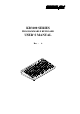
TM KB3100 SERIES PROGRAMMABLE KEYBOARD USER’S MANUAL Rev.
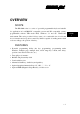
TM SOME IMPORTANT NOTES FCC NOTES This equipment generates, uses, and can radiate radio frequency energy and, if not installed and used in accordance with the instructions manual, may cause interference to radio communications. It has been tested and found to comply with limits for a Class A digital device pursuant to subpart J of Part 15 of FCC Rules, which are designed to provide reasonable protection against interference when operated in a commercial environment.
TM OVERVIEW CHAP. 1 PACKAGE CONTENTS CHAP. 2 INSTALLATION CHAP. 3 APPLICATION CHAP. 4 PROGRAMMING THE KEYBOARD CHAP. 5 SPECIFICATIONS CHAP. 6 SERVICE AND SPARE PARTS CHAP.
TM TABLE OF CONTENTS OVERVIEW . . . . . . . . . . . . . . . . . . . . . . . . . . . . . . . . . . . . . . . . . . . . . . . 1 - 1 SCOPE . . . . . . . . . . . . . . . . . . . . . . . . . . . . . . . . . . . . . . . . . . . . . . 1 - 1 FEATURES . . . . . . . . . . . . . . . . . . . . . . . . . . . . . . . . . . . . . . . . . . . 1 - 1 MODEL NUMBERS . . . . . . . . . . . . . . . . . . . . . . . . . . . . . . . . . . . . 1 - 2 PACKAGE CONTENTS . . . . . . . . . . . . . . . . . . . . . . . . . . . . . . . . . .
TM POWER ON LED . . . . . . . . . . . . . . . . . . . . . . . . . . . . . . . . . . . . . . 6 KEY SWITCH TYPE . . . . . . . . . . . . . . . . . . . . . . . . . . . . . . . . . . . 6 KEY STROKE TRAVEL . . . . . . . . . . . . . . . . . . . . . . . . . . . . . . . . 6 KEY TOP SIZE . . . . . . . . . . . . . . . . . . . . . . . . . . . . . . . . . . . . . . . . 6 PREPRINTED KEYS . . . . . . . . . . . . . . . . . . . . . . . . . . . . . . . . . . . 6 KEY CAP . . . . . . . . . . . . . . . . . . . . . . . . . . .
TM iv
TM OVERVIEW SCOPE The KB-3100 series is a series of powerful programmable keyboard suitable for application in both IBM PC compatible system and PS2 compatible system, programmable without TSR under DOS, Windows 3.1 and also Windows95 environment. This series provides 112 keys (max.) of a comfortable size 18 x 22 mm in 8 x 14 matrix and a 6 position control key which is capable of sending answer back codes according to the position of the key.
TM MODEL NUMBERS CHAP.
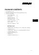
TM PACKAGE CONTENTS • • • Programmable keyboard Key clip x 1 (mounted at bottom of the programmable keyboard) Accessory bag including: ⇒ Cable CCBLA-055-2 x1 ⇒ Legend sheet x4 ⇒ Quad key w/key cap x1 ⇒ Double key w/key cap x2 ⇒ Control keys 4 pcs/set x 1 (set) ⇒ Utility software diskette x 1 ⇒ User’s manual x1 ⇒ Key cap (for single key) x 104 CHAP. 2 OPTION LIST • • • • • • • MSR (ISO track 1 & 2, ISO track 1, 2 &3, or JIS I track 2 + JIS II) /pc Soft dust cover / pc Numerical keys (.
TM CHAP.
TM INSTALLATION CABLE CONNECTION Take the cable CCBLA-055-2 out of the accessory bag and connect the 6 pin DIN male plug of the cable to the central 6 pin female connector at the bottom of the programmable keyboard (ref. Fig. 3-1), connect the other end (5 pin DIN male plug) to the PC or a compatible system. Connect the PC keyboard or any other keyboard wedged input device such as a CCD scanner to the 5 pin DIN female connector at the bottom of the programmable keyboard if such connection is required.
TM KEYTOP LAYOUT CHAP. 3 The basic layout of this programmable keyboard is a matrix with 8 rows and 14 columns to provide maximum 112 keys with the 6 position control key. However, there are means for the user to break the monotony and to improve the efficiency in application of this programmable keyboard.
TM blank keys to replace the normal individual keys around the area. The top surface of a blank key is at the ground level of the key stroke for other keys (ref. Fig. 3-7). The blank key will not be pressed down when pressed. The user may order for accessional quantity of the blank keys as option for his/her application. There are also double key and quad key available for the user to configure the programmable keyboard such that the most frequently used keys may occupy larger areas.
TM Double key LP Blank keys L4 POWER L3 L2 L1 LO Quad key MAGNETI C STRI PE READER Numerical keys CHAP. 3 Fig.
TM APPLICATION KEYBOARD CONSTRUCTION This keyboard is constructed of three parts on the top surface (ref. Fig. 4-1). A 6 position turning key switch area is at the upper right corner, a 14 x 8 matrix of push key switches occupies most of the top surface and a left-right slot near the upper edge is designed for the Magnetic Stripe Reader of the -M2, -M3, -MJ models. In the rectangular area at upper right corner there are one 6 position electronic key switch and two LED’s.
TM This turnable electronic key switch is delivered with a set of 4 pcs keys, each marked as “PRG:, “REG”, “Z” and “GT”. The effective range of each of the 4 keys can be illustrated by the following table and drawing. LP L0 L1 L2 L3 L4 PRG REG Z GT Y Y Y Y Y N N Y Y Y N N N Y Y Y Y N N Y Y Y Y Y LP L4 LO L3 L2 L1 45° POWER CHAP. 4 MAGNETIC STRIPE READER 30° 45° 30° 30° Fig.
TM PRELOADED PATTERN As the KB3100 series satisfies so many application requirements easily, it is naturally impossible to give a definite set of key definitions to serve most of its application. However, this keyboard is preloaded with a particular pattern on the page LP before it is delivered. Please refer to the print-out on next page for the key definition of each location of this preloaded pattern.
TM Print Scroll Screen Lock + – × ÷ Esc F1 F2 F3 F4 F5 F6 Esc F7 F8 F9 F10 F11 F12 ← ↓ → ~ ` ! 1 @ 2 # 3 $ 4 % 5 ^ 6 & 7 * 8 ( 9 Tab Q W E R T Y U I Cap A S D F G H J Shift Shift Z X C V B Alt Space Space Space Space Ctrl ↑ Pause Ins Home PgUp Del End PgDn ) 0 _ - + = ï O P { [ } ] | \ K L : ; ” ’ Enter Enter N M < , > .
TM MSR (Magnetic Stripe Reader) The MSR slot is near the upper edge of the Programmable Keyboard. The MSR indicator LED is located at the upper left corner of the block containing the electronic key. There are three choices of the reader types – ISO dual tracks, ISO triple tracks and JIS types. For card reading, be sure to insert the card to the bottom with magnetic stripe of ISO card or JIS I track 2 facing right.
TM JIS card The side with JIS II magnetic stripe toward user Fig. 4 - 4 Reading magnetic stripe cards of JIS standard CHAP.
TM PROGRAMMING THE KEYBOARD EASINESS IN PROGRAMMING The programmable keyboard series KB-3100 is a very powerful programmable keyboard. It can be used under any environment that any PC or PS2 keyboard can be applicable with its immense programmability. However the programming could seem to be a little bit more restrictive yet very convenient. The KB-3100 series can be programmed under Windows95, Windows 3.1, and DOS environment through application of the utility diskette attached in the accessory.
TM PC or PST SYSTEM PROGRAMMABLE KEYBOARD EXT. KB PORT PC or PS2 KEYBOARD Fig. 5 - 1 - 1 Preparations ANSWER BACK CODE CHAP. 5 Programming the answer back codes of the 6 position electronic key-lock is also very easy as they are included in the keyboard programming with the locations coded as “KLP”, “KL0”, “KL1”, “KL2”, “KL3” and “KL4” in the key-layout map of page L1.
TM HOT KEY PROGRAMMING The POSIFLEX programmable keyboard KB-3100 series supports the “hot key programming” method which is most useful in instant modification of a few keys in a preprogrammed keyboard without entering the more sophisticated programming utility. Of course, the user may also use this feature to program through out all 112 keys by 5 pages (LP and L1 to L4) at will.
TM enter the “hot key programming” mode when the programmable keyboard is already fully loaded (no more free memory for further programming) by the key contents previously programmed. INPUT THE CONTENT TO BE PROGRAMMED CHAP.
TM UTILITY INSTALLATION In the utility diskette, there is a file named “INSTALL.EXE” for installation of all the utilities into any operating system among Windows95, Windows 3.1 and DOS. In order to give the user of all levels a clear picture of what to do during installation, the installation procedures are illustrated step by step graphically below. Whenever “click” is mentioned in the text, it means that the user uses a mouse.
TM Click the “Run” command in the start menu, as indicated in Fig. 5-2-2. Fig. 5 - 2 - 2 CHAP. 5 Refer to Fig. 5-2-3, the dialogue box of the “Run” command, the user may type in “A:install.exe” in the command line for “Open” and click “OK” just the way like in Fig. 5-2-7, or the user may also click “Browse” to find the installation program with the help of the computer. Fig.
TM In the Browse box, use the arrow button to find the “Desktop” and click it. The screen will look like Fig. 5-2-4. Fig. 5 - 2 - 4 Clicking the “Desktop” in the “Look in” command line, the resource list will be unfolded. Find and click the “3 ½ Floppy (A:)” in “My Computer” to get access of drive A: as in Fig. 5-2-5 CHAP. 5 Fig.
TM Double click the file “Install.exe” or click the file only once and click the “Open” button, as in Fig. 5-2-6. Fig. 5 - 2 - 6 The dialogue box of the “Run” command reappears with the proper file name in the “Open” command line. Now click “OK” to start installation. CHAP. 5 Fig.
TM A screen like Fig. 5-2-8 will appear, press the “y” key to continue installation. Fig. 5 - 2 - 8 Another question will show up to ask you if you want to install the utility for the Windows 3.1 or Windows95 as in Fig. 5-2-9. The utility will detect automatically which Windows is being used and install itself in a correct way. Now, let us press the “y” key to install the utility for the Windows environment. Fig. 5 - 2 - 9 5-2- 5 CHAP.
TM On the screen, there will be an input area to enter the path to the directory where the current Windows system files are. The default value for this input is shown on the screen like Fig. 5-2-10. CHAP. 5 Fig. 5 - 2 - 10 However, this path can be edited to the actual situation of the user’s system by using the left / right arrow keys, “insert”, “delete”, “home”, “end” and those keys needed to type in the correct directory path. One example is given in Fig. 5-2-11. Fig.
TM Pressing the “enter” key from either Fig. 5-2-10 or Fig. 5-2-11, a question arises again asking if the user wants to install the utility like in Fig. 5-2-12. Fig. 5 - 2 - 12 After the user presses the “y” key confirming the intention, the installation starts and a message “COPYING FILES” shows up briefly as in Fig. 5-2-13 together with some beeps denoting the installation progress from time to time. CHAP. 5 Fig.
TM After a while, the screen will be like in Fig. 5-2-14. The utility is copied and some modifications of the system parameters of the Windows system are ready yet a restart of Windows is required to make these modifications effective. Fig. 5 - 2 - 14 To restart a Windows95, click the “Start” button as in Fig. 5-2-15. CHAP. 5 Fig.
TM When the start menu shows up, the user may notice that a new icon named as “Posiflex” with a keyboard shape icon is in the start menu. To restart the Windows95, click “Shut Down” as in Fig. 5-2-16. New icon Fig. 5 - 2 - 16 When the shut down windows appear, click “Restart the computer?” and click “Yes” as in Fig. 5-2-17. After this restart, the user is free to program this keyboard. CHAP. 5 Fig.
TM WINDOWS 3.1 INSTALLATION Insert the programmable keyboard utility diskette in drive A: and double click the icon for “Main” group as shown in Fig. 5-2-18. Fig. 5 - 2 - 18 When the components of Main group show up, double click the “File Manager” as shown in Fig. 5-2-19. CHAP. 5 Fig.
TM The screen like the one in Fig. 5-2-20 will show up. Now double click the box that stands for drive A: Fig. 5 - 2 - 20 The utilities in the diskette in drive A: will show up and now double click the file “install.exe” as shown in Fig. 5-2-21 CHAP. 5 Fig.
TM The following procedures are just like those for Windows95. The screen like Fig. 5-2-22 appears. Press “y” key to continue installation. Fig. 5 - 2 - 22 To the question in Fig. 5-2-23, press “y” to continue. CHAP. 5 Fig.
TM On the screen, there will be an input area to enter the path to the directory where the current Windows system files are. The default value for this input is shown on the screen like Fig. 5-2-24. Fig. 5 - 2 - 24 This path can be edited to the directory where the Windows 3.1 is, like the example in Fig. 5-2-25. Then press the “enter” key. CHAP. 5 Fig.
TM Press “y” when the following question: “ready to install?” shows up as shown in Fig. 5-2-26. Fig. 5 - 2 - 26 A message “COPYING FILES” will show up with some beeps as shown in Fig. 5-2-27. CHAP. 5 Fig.
TM After the copying is completed, the installation procedures are done. Yet, the Windows must be restarted to make the newly installed utility work. DOS INSTALLATION Insert the programmable keyboard utility diskette in drive A: and type under A:\> prompt the following command: A:\> install (enter) The screen will change to Fig. 5-2-28: CHAP. 5 Fig. 5 - 2 - 28 Answer “y” to the above question, the screen will become to Fig.
TM Fig. 5 - 2 - 29 Answer “n” to the above question. All the necessary files will be copied to the directory “POSIFLEX.D”, and the installation is completed. CHAP.
TM STARTING PROGRAMMING UNDER WINDOWS95 In the initial screen when Windows95 starts after proper installation, the user may find an icon named as “Posiflex” as shown in Fig. 5-3-1 and double click it. New icon Fig. 5 - 3 - 1 Or, the user may find the icon in start menu as shown in Fig. 5-3-2 and click it. New icon Fig. 5 - 3 - 2 5-3- 1 CHAP.
TM Once the programming utility (KBM.EXE) is activated as shown in the above, the paragraph under “STARTING KBM.EXE” in this section applies. UNDER WINDOWS 3.1 After restarting the Windows 3.1 once the installation is done, there is an icon of the group marked as “Posiflex Keyboard Utilities” in the Program Manager. Move this icon to suitable position if required. To start programming of the keyboard under Windows 3.1, double click this icon as shown in Fig. 5-3-3. CHAP. 5 Fig.
TM Fig. 5 - 3 - 4 Once the programming utility (KBM.EXE) is activated as shown in the above, the paragraph under “STARTING KBM.EXE” in this section applies. UNDER DOS To start programming the keyboard under DOS environment, the user has to change directory to the “POSIFLEX.D” which was established through installation, and then type the command “KBM” followed by pressing the “enter” key. The paragraph “STARTING KBM.EXE” applies for the actions to take afterwards.
TM SHORTCUT UTILITY (RWM.EXE) The feature of this RWM.EXE is designed mainly for the off-line programming purpose and is very useful in quick reproduction of the preprogrammed contents of the programmable keyboard. In such application, the user should have either the preprogrammed keyboard or the preprogrammed file with “.tpl” extension name which is the result of the keyboard programming. The user may use RWM.EXE to directly transfer the programmed result of the programmable keyboard to a “.
TM STARTING KBM.EXE In case that the program KBM.EXE is executed for off-line programming, that is executing KBM.EXE on a normal PC compatible machine without the programmable keyboard attached, the program will ask a question on the display as the following: Fig. 5 - 3 - 5 The user should select 4 for a KB-3100 series or standard PST programmable keyboard. If any key other than number 1 to 4 is pressed, the program will be terminated automatically.
TM Fig. 5 - 3 - 6 If the user presses the “ESC” key to the question in Fig. 5-3-6, the process of Fig. 5-3-7 is skipped and Fig. 5-3-8 will show up. However, pressing any other key, the user will find the screen like in Fig. 5-3-7 for a moment Posiflex Programmable Keyboard Utility vx.xx.xx CHAP. 5 reading data from the keyboard . . . Fig. 5 - 3 - 7 Then the screen like Fig.
TM Cursor position Program ID Editing area Key-layout map Key-contents area Positon control keys Command list Status bar Fig. 5 - 3 - 8 In the above, each area of the screen is labeled with its function. The user may start programming right away with the arrow keys to move around in the key layout map to select the key or the position control key to edit the content. The user may also use the “PgUp” / “PgDn” key to select for different page (total 5 pages).
TM COMMAND LISTING IN VIEW MODE CHAP.
TM Alt-W -- write key definitions to the programmable keyboard Alt-X -- quit the keyboard programming program any other key stoke -- will be taken as an input in ASCII-code editing mode, and will give no influence if the current key was last edited in scan-code editing mode COMMAND LISTING IN ASCII-CODE EDITING MODE ESC -- enter view mode F1 -- get help on command list of ASCII- code editing mode F5 -- enter view mode F8 -- enter view mode F10 -- enter view mode BkSp -- delete the character to the left of
TM COMMAND LISTING IN SCAN-CODE EDITING MODE CHAP. 5 ESC -- leading code to enter scan code of any key after it into key-content, except “ESC” + “F” for utility version since 2.15.xx ESC-F -- leading code of arbitrary release code for utility version since 2.15.xx. usually used to release “CTL”, “ALT” or “SHF”.
TM SPECIFICATIONS CONSTRUCTION: CASE MATERIALS: POWER ON LED: KEY SWITCH TYPE: KEY STROKE TRAVEL: KEY TOP SIZE: PREPRINTED KEYS: KEY CAP: PROGRAMMABILITY: • METHOD: • • • • • • • • • • Spill-proof, 112 keys + 6 position control key ABS 94V0 Green membrane plus rubber dome 3.2 mm 18 x 22 mm for normal keys (ivory) “.”, “00”, “0 to “9” 18 x 22 mm transparent Software under DOS, Windows 3.
TM • 5 pin DIN female connector: connect to input PC keyboard or Daisy Chain device • 6 pin mini DIN female connector: connect to input PS2 keyboard Connects to PC through CCBLA-055-2 Connects to PC keyboard or Daisy Chain device Connects to PS2 keyboard MAGNETIC STRIPE READER: • Decoder & interface............. Built in keyboard wedge interface • Tracks..................................
TM POWER CONSUMPTION: Voltage...................... 5VDC±10% Current...................... 25 mA max. (Model KB3100) 50 mA max. (Models KB3100M2, KB3100M3, KB3100MJ) MECHANICAL: Dimension in mm.......346 mm x 210 mm x 57 mm Dimension in inches...13.6”x 8.3”x 2.2” (W x D x H) ENVIRONMENTAL: Operating temperature...... Storage temperature......... Relative humidity............. Vibration.......................... Shock...............................
TM CHAP.
TM SERVICE AND SPARE PARTS 120 101 119 102 118 103 LP L4 LO R POWE L3 L2 L1 ETICPE MAGNSTRI ER READ 104 105 117 106 107 108 109 110 116 115 CHAP.
TM Location Choice CHAP.
TM CHAP.
TM CHAP. 1 OVERVIEW CHAP. 2 PACKAGE CONTENTS CHAP. 3 INSTALLATION CHAP. 4 APPLICATION CHAP. 5 PROGRAMMING THE KEYBOARD CHAP. 6 SPECIFICATIONS CHAP.